
RICAMBI ORIGINALI
ORIGINAL SPARE PARTS
PIECES DE RECHANGE ORIGINALES
ORIGINALERSATZTEILE
REPUESTOS ORIGINALES
ORIGINEEL ONDERDEEL
SCHEDA ELETTRONICA
CONTROL BOARD
CARTE ELECTRONIQUE
STEUER PLATINE
TARJETA ELECTRONICA
ELEKTRONISCHE PRINTKAART
Nederlands NL
Español ES
Deutch DE
Français FR
English EN
Italiano IT
ZC5

QUADRO COMANDO
ZC5
PROG
TCATL +-+-
L1 L2 UVWE 10 11 12 3 C1
4 F FA FC
B
E
+
T
T
T
T
T
T
T
T
T
C
C
C
C
C
C
C
C
C
A
A
A
A
A
A
A
A
A
A
A
A
T
T
T
T
T
T
T
T
T
L
L
L
L
L
L
L
L
L
+
+
+
+
+
+
+
+
+
+
+
+
+
+
+
+
+
+
-
-
-
TC
A
A
A
A
T
L
+
+
+
T
C
A
A
TL
+
E
T
T
T
T
T
T
T
T
T
T
T
T
T
++
+
+
+
+
+
+
+
+
T
T
T
T
T
T
T
P
P
P
PRO
PRO
PRO
PRO
PRO
G
G
G
G
G
G
G
G
G
G
A
A
A
A
-
A
A
A
-
A
A
A
A
-
PRO
PRO
PR
PRO
PRO
PRO
PRO
PRO
G
G
G
G
G
A
D
C
B

ITALIANO
Pag.
3
- Codice manuale:
319LR15
319LR15 ver.
1.0
1.0 12/2007 © CAME cancelli automatici s.p.a.
I dati e le informazioni indicate in questo manuale sono da ritenersi suscettibili di modifica in qualsiasi momento e senza obbligo di preavviso da parte di CAME cancelli automatici s.p.a.
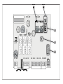
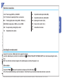
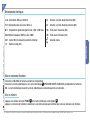
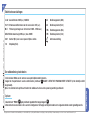
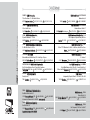
Collegamenti elettrici
IT
L1-L2 Alimentazione 230V (a.c.) 50/60 Hz
10-11
Alimentazione accessori 24V (a.c.) max. 20W
W-E
Lampeggiatore di movimento (Port. cont.: 230V - 25W max.)
U-V-W
Motore monofase 230V (a.c.) max. 500W
2-C1 Contatto (N.C.) di riapertura durante la chiusura
1-2
Pulsante di stop (contatto N.C.)
2-3
Selettore a chiave e/o pulsante di apertura (N.O.)
2-4
Selettore a chiave e/o pulsante di chiusura (N.O.)
F-FA
Finecorsa di apertura (contatto N.C.)
F-FC
Finecorsa di chiusura (contatto N.C.)
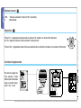
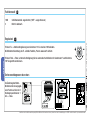
Collegamento antenna
-Collegare il cavo RG58 dell’antenna agli appositi morsetti.
-Innestare la scheda di radiofrequenza sulla scheda elettronica D DOPO AVER TOLTO LA TENSIONE (o scollegato le batterie).
N.B.: La scheda elettronica riconosce la scheda di radiofrequenza solo quando viene alimentata.
Attivazione del comando radio
Memorizzazione
-Tenere premuto il tasto “PROG” A sulla scheda elettronica. Il led lampeggia. B
-Premere il tasto del trasmettitore da memorizzare. Il led rimarrà acceso a segnalare l’avvenuta memorizzazione.

ITALIANO
I dati e le informazioni indicate in questo manuale sono da ritenersi suscettibili di modifica in qualsiasi momento e senza obbligo di preavviso da parte di CAME cancelli automatici s.p.a.
Pag.
4
- Codice manuale:
319LR15
319LR15 ver.
1.0
1.0 12/2007 © CAME cancelli automatici s.p.a.
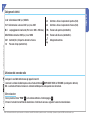
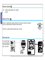
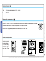
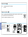
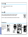
Regolazioni E
Selezione funzioni C
1 ON “Chiusura automatica” attivata; (1 OFF - disattivata)
2 Non utilizzato
Limitatore di coppia motore
Per variare la coppia mo-
trice, spostare il faston
indicato (con fi lo di colore
nero) su una delle 4 posi-
zioni; 1 min. - 4 max
Trimmer T.L. = Regolazione tempo lavoro da un minimo di 15 secondi a un massimo di 120 secondi.
Se il TL è regolato al minimo si attiva la funzione “uomo presente”.
Trimmer T.C.A. = Regolazione tempo di chiusura automatica da un minimo di 0 secondi a un massimo di 120 secondi.
1234
L2T L1T
02412
12 3 4
L2T L1T
024
12
L1T L2T C T 0 12 24
QUADRO COMANDO
ZC5
PROG
TCATL +-+-
L1 L2 UVWE 10 11 12 3 C14FFAFC
1234
1234
L1T L2T CT 0 12 24
QUADRO COMANDO
ZC5
PROG
TCATL +-+-
L1 L2 U V W E 10 11 1 2 3 C14 F FA FC

ITALIANO
Pag.
5
- Codice manuale:
319LR15
319LR15 ver.
1.0
1.0 12/2007 © CAME cancelli automatici s.p.a.
I dati e le informazioni indicate in questo manuale sono da ritenersi suscettibili di modifica in qualsiasi momento e senza obbligo di preavviso da parte di CAME cancelli automatici s.p.a.
I nostri prodotti sono realizzati con materiali diversi. La maggior parte di essi (alluminio, plastica, ferro, cavi elettrici) è assimilabile ai rifi uti
solidi e urbani. Possono essere riciclati attraverso la raccolta e lo smaltimento differenziato nei centri autorizzati.
Altri componenti (schede elettroniche, batterie dei transmettitori etc.) possono invece contenere sostanze inquinanti.
Vanno quindi rimossi e consegnati a ditte autorizzate al recupero e allo smaltimento degli stessi.
Dismissione e smaltimento


The data and information reported in this installation manual are susceptible to change at any time and without obligation on CAME cancelli automatici s.p.a. to notify users.
Pag.
7
- Manual code:
319LR15
319LR15 ver.
1.0
1.0 12/2007 © CAME cancelli automatici s.p.a.
ENGLISH
Electrical connections
EN
-Connect the antenna’s RG58 cable to the apposite terminals.
-Lock the radiofrequency card into the electronic card D AFTER CUTTING OFF THE POWER SUPPLY (or after disconnecting the batte-
ries).
N.B.: the electronic card only recognises the radiofrequency card when the power is on.
Activating the remote control
Memorisation
-Keep the “PROG” A button on the electronic card pressed. The LED fl ashes. B
-Press the transmitter button you wish to memorise. The LED will stay on to show memorisation has been successful.
L1-L2 Power supply 230V (a.c.) 50/60 Hz
10-11 Terminals for powering 24V (a.c.) accessories
W-E
Flashing light (socket rating: 230V - 25W max.)
U-V-W
Motor single-phase 230V (a.c.) max. 500W
2-C1
Re-open during closing (N.C.) socket
1-2
Stop button (N.C. socket)
2-3
Keyswitch and/or open button (N.O.)
2-4
Keyswitch and/or close button (N.O.
F-FA
Opening limit switch (N.C.)
F-FC
Closure limit switch (N.C.)
Connection of antenna

The data and information reported in this installation manual are susceptible to change at any time and without obligation on CAME cancelli automatici s.p.a. to notify users.
Pag.
8
- Manual code:
319LR15
319LR15 ver.
1.0
1.0 12/2007 © CAME cancelli automatici s.p.a.
ENGLISH
Selection of functions C
1 ON Automatic closing enabled; (1 OFF - disabled)
2 Not used
Trimmer T.L. = Operation time setting for a minimum of 15 seconds to a maximum of 120 seconds.
If the TL is set to the minimum, the “dead man” mode is activated.
Trimmer T.C.A. = Adjusts automatic closing time (min.0”, max.120”).
To vary the motor torque,
move the indi cated faston
to one of the four posi-
tions: 1=min, 4=max
Adjustment Trimmer E
Motor torque limiter
1234
1234
L1T L2T CT 0 12 24
QUADRO COMANDO
ZC5
PROG
TCATL +-+-
L1 L2 U V W E 10 11 1 2 3 C14FFAFC
1234
L2T L1T
02412
12 3 4
L2T L1T
024
12
L1T L2T C T 0 12 24
QUADRO COMANDO
ZC5
PROG
TCATL +-+-
L1 L2 UVWE 10 11 12 3 C14FFAFC

The data and information reported in this installation manual are susceptible to change at any time and without obligation on CAME cancelli automatici s.p.a. to notify users.
Pag.
9
- Manual code:
319LR15
319LR15 ver.
1.0
1.0 12/2007 © CAME cancelli automatici s.p.a.
ENGLISH
Disposal
This product, including the packaging, is made up of several types of materials that can be recycled.
Investigate the recycling or disposal systems of the product, complying with prevailing local legislation.
Some electronic components may contain polluting substances. Do not litter.


Pag.
11
11 - Code manuel:
319LR15
319LR15 ver.
1.0
1.0 12/2007 © CAME cancelli automatici s.p.a.
Les données et les indications fournies dans ce manuel d’installation peuvent subir des modifications à tout moment sans avis préalable de la part de CAME cancelli automatici s.p.a.
FRANÇAIS
Branchements électriques
FR
-Branchez le câble RG58 de l’antenne aux borniers correpondants.
-Branchez la carte de radiofréquence sur la carte électronique D APRÈS AVOIR COUPÉ LE COURANT (ou débranchez les batteries).
N.B. : La carte électronique reconnaît la carte de radiofréquence seulement quand elle est alimentée.
Mise en service de l’émetteur
Mise en mémoire
-Appuyez sans relâcher la touche “PROG” A sur la carte électronique. La led clignote. B
-Appuyez sur la touche de l’émetteur à mémoriser. La led restera allumée pour confi rmer que la mise en mémoire a été effectuée.
L1-L2 Alimentation 230V (a.c.) 50/60 Hz
10-11
Alimentation des accessoires 24V (a.c.)
W-E
Clignotant de signalisation (portée cont. : 230V - 25W max.)
U-V-W
Moteur monophasé 230V (c.a.)max. 500W
2-C1 Contact (N.C.) de réouverture pendant la fermeture
1-2 Boutons de stop (N.C.)
2-3 Sélecteur à clé et/ou bouton d’ouverture (N.O.)
2-4 Sélecteur à clé et/ou bouton de fermeture (N.O.)
F-FA Fin de course d’ouverture
(N.C.)
F-FC
Fin de course fermeture (N.C.)
Conexión antena

Les données et les indications fournies dans ce manuel d’installation peuvent subir des modifications à tout moment sans avis préalable de la part de CAME cancelli automatici s.p.a.
Pag.
12
12 - Code manuel:
319LR15
319LR15 ver.
1.0
1.0 12/2007 © CAME cancelli automatici s.p.a.
FRANÇAIS
Réglages des compensateurs E
Limiteur de couple moteur
Selezione funzioni C
Pour varier le couple
du moteur, déplacer
le connecteur indiqué
sur l’une des 4 posi-
tions; 1 min. - 4 max.
1 ON Fermeture automatique activé; (1 OFF - éteinte)
2 Pas utilisé
Trimmer T.L. = Réglage du temps de fonctionnement d’un minimum de 15 secondes à un maximum de 120 secondes.
La fonction “homme présent” s’active si le compensateur TL est réglé au minimum.
Trimmer T.C.A. = Réglage du temps de fermeture automatique (min. 0”, max. 120”).
1234
1234
L1T L2T CT 0 12 24
QUADRO COMANDO
ZC5
PROG
TCATL +-+-
L1 L2 U V W E 10 11 1 2 3 C14 F FA FC
1234
L2T L1T
02412
12 3 4
L2T L1T
024
12
L1T L2T C T 0 12 24
QUADRO COMANDO
ZC5
PROG
TCATL +-+-
L1 L2 UVWE 10 11 12 3 C14FFAFC

Pag.
13
13 - Code manuel:
319LR15
319LR15 ver.
1.0
1.0 12/2007 © CAME cancelli automatici s.p.a.
Les données et les indications fournies dans ce manuel d’installation peuvent subir des modifications à tout moment sans avis préalable de la part de CAME cancelli automatici s.p.a.
FRANÇAIS
Cet appareil, y compris l’emballage, est constitué de plusieurs types de matériaux pouvant être recyclés.
S’informer sur les systèmes de recyclage ou d’élimination de l’appareil en se conformant aux lois locales en vigueur.
Certains composants électroniques pourraient contenir des substances polluantes, ne pas les jeter n’importe où.
Recyclage et élimination

Seite
15
15 - Handbuch-Code:
319LR15
319LR15 ver.
1.0
1.0 12/2007 © CAME cancelli automatici s.p.a.
Sämtliche in der Installationsanleitung aufgeführten Daten und Informationen können jederzeit und ohne Vorankündigung von CAME cancelli automatici s.p.a verändert werden.
DEUTSCH
Elektrischer anschluss
DE
-Kabel RG58 der Antenne an die dafür vorgesehenen Klemmen anschließen.
-Funksteckmodul auf der Steuerplatine aufstecken D, NACH UNTERBRECHUNG DER STROMZUFUHR (bzw. nach Entfernung der Batterien).
N.B.: Die Steckkarte erkennt das Funksteckmodul nur wenn sie mit Strom gespeist wird.
Aktivierung des Senders
Speichem
-Den Taster “PROG” A auf der Steuerplatine gedrückt halten. Das Led blinkt. B
-Den zu speichernden Taster auf dem Sender drücken. Das Led bleibt an und zeigt so die erfolgte Speicherung an.
L1-L2
Anschluss 230V (a.c.) 50/60 Hz
10-11
Klemmen für den elektrischen Anschluss der Zubehörteile
24V (a.c.)
W-E
Warnleuchte (Anschlussleistung: 230V – 25W max.)
U-V-W
Einphasenmotor 230V (Wechselstrom) max. 500W
2-C1
Kontakt (N.C.) «Reversierung während des Zulaufs»
1-2
Stopp-Taster (N.C.)
2-3
Taste Öffnen (Arbeitskontakt)
2-4
Taste Schließen (Arbeitskontakt)
F-FA Öffnungsendeschalter
(N.C.)
F-FC Schließungsendschalter
(N.C.)
Antennenanschluss

Sämtliche in der Installationsanleitung aufgeführten Daten und Informationen können jederzeit und ohne Vorankündigung von CAME cancelli automatici s.p.a verändert werden.
Seite
16
16 - Handbuch-Code:
319LR15
319LR15 ver.
1.0
1.0 12/2007 © CAME cancelli automatici s.p.a.
DEUTSCH
Funktionswahl C
Regolazioni E
1 ON Schließautomatik zugeschaltet; (1 OFF - ausgeschlossen)
2 Nicht in Gebrauch
Drehmomentbegrenzer des motors
Zur Änderung des Motor-
Drehmoments den angegeb-
enen Faston auf eine der 4
Stel lungen positio nieren: 1
min. - 4 max.
Trimmer T.L. = Arbeitszeitregulierung von mindestens 15 bis maximal 120 Sekunden.
Bei Mindestzeiteinstellung des TL wird die Funktion „Person anwesend” aktiviert.
Trimmer T.C.A. = Timer, auf dem die Verzögerung für das automatische Schließen mit mindestens 0” und höchstens
120” eingestellt werden kann.
1234
1234
L1T L2T CT 0 12 24
QUADRO COMANDO
ZC5
PROG
TCATL +-+-
L1 L2 U V W E 10 11 1 2 3 C14 F FA FC
1234
L2T L1T
02412
12 3 4
L2T L1T
024
12
L1T L2T C T 0 12 24
QUADRO COMANDO
ZC5
PROG
TCATL +-+-
L1 L2 UVWE 10 11 12 3 C14FFAFC

Seite
17
17 - Handbuch-Code:
319LR15
319LR15 ver.
1.0
1.0 12/2007 © CAME cancelli automatici s.p.a.
Sämtliche in der Installationsanleitung aufgeführten Daten und Informationen können jederzeit und ohne Vorankündigung von CAME cancelli automatici s.p.a verändert werden.
DEUTSCH
Dieses Produkt einschließlich Verpackungen besteht aus verschiedenen wiederverwertbaren Materialien.
Informieren Sie sich unter Berücksichtigung der örtlich geltenden Rechtsvorschriften über die Recycling- und Entsorgungssysteme des
Produkts.
Einige elektronische Bauteile könnte verschmutzende Substanzen enthalten – nicht in der Umwelt zerstreuen.
Entsorgung


Pag.
19
19 - Codigo manual:
319LR15
319LR15 ver.
1.0
1.0 12/2007 © CAME cancelli automatici s.p.a.
Los datos y las informaciones indicadas en este manual de instalación podrían modificarse en cualquier momento y sin obligación de aviso previo por parte de la firma CAME cancelli automatici s.p.a.
ESPAÑOL
Conexiones eléctricas
ES
-Conectar el cable RG58 de la antena a los respectivos bornes.
-Insertar la tarjeta de radiofrecuencia en la tarjeta electrónica D DESPUÉS DE HABER QUITADO LA TENSIÓN (o desconectado las baterías).
Nota: La tarjeta electrónica reconoce la tarjeta de radiofrecuencia sólo cuando es alimentada.
Activación del mando radio
Memorización
-Tener apretada la tecla “PROG” A en la tarjeta electrónica.El led parpadea. B
-Apretar la tecla del transmisor a memorizar: El led quedará encendido lo que indica que la memorización se ha verifi cado.
L1-L2 Alimentación 230V (a.c.) 50/60 Hz
10-11
Alimentación de los accesorios 24V (a.c.) max. 20W
W-E
Lámpara intermitente de señalización (230V - 25W máx.)
U-V-W
Motor monofásico 230V (a.c.) max. 500W
2-C1 Contacto (n.c.) de «reapertura durante el cierre»
1-2 Pulsador de stop (N.C.)
2-3
Selector de llave y /o pulsador de apertura (N.O.)
2-4
Selector de llave y /o pulsador de cierre (N.O.)
F-FA
Final de carrera de apertura (N.C.)
F-FC
Final de carrera de cierre (N.C.)
Conexión antena

Los datos y las informaciones indicadas en este manual de instalación podrían modificarse en cualquier momento y sin obligación de aviso previo por parte de la firma CAME cancelli automatici s.p.a.
Pag.
20
20 - Codigo manual:
319LR15
319LR15 ver.
1.0
1.0 12/2007 © CAME cancelli automatici s.p.a.
ESPAÑOL
Selecciones funciones C
1 ON Cierre automático activado; (1 OFF - desactivado)
2 No se utiliza
Para variar el par motor,
desplazar el faston
indicado hasta una de las
4 posi ciones; 1 mín. - 4
máx.
Trimmer T.L. = regulación tiempo de funcionamiento desde un mínimo de 15 segundos a un máximo de 120 segundos.
Si el TL se regula al mínimo se activa la función “hombre muerto “.
Trimmer T.C.A. = Régulación cierre automático (min. 0”, max. 120”).
Réglages des compensateurs E
Limitador de par motor
1234
1234
L1T L2T CT 0 12 24
QUADRO COMANDO
ZC5
PROG
TCATL +-+-
L1 L2 U V W E 10 11 1 2 3 C14 F FA FC
1234
L2T L1T
02412
12 3 4
L2T L1T
024
12
L1T L2T C T 0 12 24
QUADRO COMANDO
ZC5
PROG
TCATL +-+-
L1 L2 UVWE 10 11 12 3 C14FFAFC

Pag.
21
21 - Codigo manual:
319LR15
319LR15 ver.
1.0
1.0 12/2007 © CAME cancelli automatici s.p.a.
Los datos y las informaciones indicadas en este manual de instalación podrían modificarse en cualquier momento y sin obligación de aviso previo por parte de la firma CAME cancelli automatici s.p.a.
ESPAÑOL
Este producto, incluido el embalaje, está hecho con diferentes tipos de materiales que pueden reciclarse.
Infórmese sobre los sistemas de reciclaje o eliminación del producto, respetando las normas locales vigentes.
Algunos componentes electrónicos podrían contener substancias contaminantes; no los abandone en el medio ambiente.
Desguase
Seite wird geladen ...
Seite wird geladen ...
Seite wird geladen ...
Seite wird geladen ...
Seite wird geladen ...
Seite wird geladen ...
-
 1
1
-
 2
2
-
 3
3
-
 4
4
-
 5
5
-
 6
6
-
 7
7
-
 8
8
-
 9
9
-
 10
10
-
 11
11
-
 12
12
-
 13
13
-
 14
14
-
 15
15
-
 16
16
-
 17
17
-
 18
18
-
 19
19
-
 20
20
-
 21
21
-
 22
22
-
 23
23
-
 24
24
-
 25
25
-
 26
26


in anderen Sprachen
- español: CAME Z24-Z230
- italiano: CAME Z24-Z230
Verwandte Artikel
-
CAME C BYT Benutzerhandbuch
-
-
CAME Z Series Benutzerhandbuch
-
-
-
-
-
-
CAME ZC3C Bedienungsanleitung
-