


Alle Rechte vorbehalten. Irrtümer und Änderungen vorbehalten.
1 Zu Ihrer Sicherheit
GEFAHR
Ge
fahr der Unwirksamkeit der Schutzeinrichtung
Der Gefahr bringende Zustand der Maschine wird bei Nichtbeachtung möglicherweise
nicht oder nicht rechtzeitig beendet.
b
Beachten Sie den beiliegenden Sicherheitshinweis.
Der Sicherheits-Lichtvorhang ist unter anderem für nachfolgende Verwendungen nicht
geei
gnet:
•
Im Freien
•
Unter Wasser
•
In explosionsgefährdeten Bereichen
•
In Umgebungen mit erhöhter ionisierender Strahlung
•
In Höhen über 3000 m ü. NHN
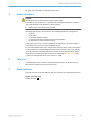
Im isolierten 24-V-DC-Versorgungsstromkreis zum Gerät muss eine Sicherung mit
einem Nennstrom von maximal 4 A angebracht werden, um den verfügbaren Strom zu
begrenzen.
Weitere Informationen zur Arbeit mit der Schutzeinrichtung enthält die Maschinendoku‐
mentation oder die Betriebsanleitung der Schutzeinrichtung. Sie finden die EU-Konfor‐
mitätserklärung und die aktuelle Betriebsanleitung der Schutzeinrichtung, indem Sie
auf www.sick.com im Suchfeld die Artikelnummer eingeben (Artikelnummer: siehe
Typenschildeintrag im Feld „Ident. no.“).
2 Twin-Stick
Der Sicherheits-Lichtvorhang besteht aus 2 identischen Twin-Sticks kleiner Baugröße.
Jeder T
w
in-Stick enthält sowohl die Sende- als auch Empfangseinheit.
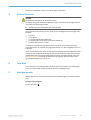
3 Anzeigeelemente
Vollständige Übersicht der LED-Zustände und ihrer Bedeutungen: siehe Betriebsanlei‐
t
un
g.
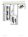
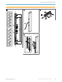
Anzeigen des Twin-Sticks
Position der LEDs:
A
MONTAGEANLEITUNG
8022846/11KJ/2018-10-22 | SICK M O N T A G E A N L E I T U N G | TWINOX4
3
Irrtümer und Änderungen vorbehalten

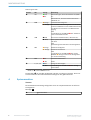
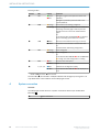
Bedeutung der LEDs
Position LED Anzeige Bemerkung
!
OUT
O Gr
ün
O
Rot
LED leuchtet grün, wenn Schutzfeld frei ist (OSSD
an).
LED leuchtet rot, wenn Schutzfeld unterbrochen
(OS
SD aus) ist.
"
EDM
O Orange
Sc
hützkontrolle konfiguriert.
Ö Orange
D
er Sicherheits-Lichtvorhang erwartet für die Konfi‐
gura
tion von EDM beim ersten OSSD-Statuswechsel
den Wechsel von 24 V auf 0 V am Multifunktions‐
eingang.
Oder:
In Verbindung mit der ERR-LED Ö Rot: Schützkon‐
trolle meldet defekte Schütze
§
COM
O Weiß
Ext
erne Kommunikation aktiv (z. B. für Service).
Ö Weiß
K
eine optische Kommunikation zu einem anderen
Tw
in-Stick.
Oder:
Rückmeldung beim Deaktivieren der Konfiguration
$
RES
O Or
ange
R
ücksetzen konfiguriert.
Ö Orange
R
ücksetzen erforderlich.
Oder:
In Ver
bindung mit der ERR-LED Ö Rot und der
EDM-LED Ö Orange: Fehler bei der Konfiguration
bzw. bei der Verkabelung.
%
ERR
O Rot
Schutzfeld unterbrochen.
Ö Rot
F
ehler.
&
1, 2, 3, 4, 5
O Blau
Anzeige der Ausrichtgüte.
Ö Blau In Verbindung mit der ERR-LED Ö Ro
t: Anzeige
eines Fehlers.
o LED aus
. Ö LED blinkt. O
LED leuchtet.
Die OUT-LED (!) ist me
hrfach angebracht und kann rot oder grün leuchten. Sie ist nur
an zwei Positionen des Sicherheits-Lichtvorhangs mit OUT gekennzeichnet.
4 Systemanschluss
Überblick
D
er S
icherheits-Lichtvorhang verfügt über einen 10-m-Systemanschluss mit offenem
Leitungsende.
Montage: B
!
Systemanschluss
MONTAGEANLEITUNG
4
M O N T A G E A N L E I T U N G | TWINOX4 8022846/11KJ/2018-10-22 | SICK
Irrtümer und Änderungen vorbehalten

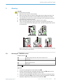
5 Montieren
VORSICHT
Bei der Monta
ge besonders beachten:
b
Die Twin-Sticks stets auf einem planen Untergrund montieren.
b
Bei der Montage auf die korrekte Ausrichtung des Sicherheits-Lichtvorhangs ach‐
ten. Die beiden Gehäuse der Twin-Sticks müssen sich exakt gegenüberliegen.
b
Geeignete Maßnahmen zur Schwingungsdämpfung treffen, wenn die Schockanfor‐
derungen über den Werten in Abschnitt Datenblatt liegen.
b
Bei der Montage den Mindestabstand des Systems einhalten.
b
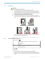
Den Sicherheits-Lichtvorhang so montieren, dass Untergreifen, Übergreifen und
Hintertreten sowie ein Verschieben des Sicherheits-Lichtvorhangs ausgeschlossen
sind.
Abbildung 1: Durch richtige Montage (oben) müssen die Fehler (unten) Hintertreten, Unter‐
gr
eifen und Übergreifen ausgeschlossen werden
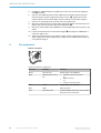
5.1 Halterung TWINOX4 montieren
Halterung TWINOX4: C
!
4 x Befestigungsschraube M5x25 mit Kugelpfanne und Dichtung für
Ab
standshalter
"
Dichtung für Halter
§
Halterbasis
$
Abstandshalter mit Dichtung für Abstandshalter
%
Leitungsverschraubung
Montage: D
Vorgehensweise
1.
Die Leit
ungsverschraubung von der Halterbasis abschrauben (!).
2.
Das Kabel durch die rechteckige Öffnung der Dichtung durchführen ("). Dabei
darauf achten, dass die Dichtung mit der hervorstehenden Kante zur Halterbasis
zeigt.
MONTAGEANLEITUNG
8022846/11KJ/2018-10-22 | SICK M O N T A G E A N L E I T U N G | TWINOX4
5
Irrtümer und Änderungen vorbehalten

3. Das Kabel von innen nach außen durch die Halterbasis führen und dann durch die
Leit
ungsverschraubung führen (§), bis sich die Halterung dicht am TWINOX4
befindet.
4.
Das Kabel in die Zugentlastung in der Halterbasis einklemmen ($).
5. Halterung TWINOX4 an die Rückseite des Twin-Sticks heranführen und die Dich‐
tung (%) korrekt ausrichten.
6. Halterung TWINOX4 mit 2 M5-Schrauben mit Kugelpfanne und Dichtung für
Abstandshalter mit einem Anzugsdrehmoment von maximal 4 Nm verschrauben
(&). Schrauben gleichmäßig anziehen, bis die Dichtungen flächig anliegen. Die
Dichtungen sollten beim Verschrauben nicht verrutschen.
7. Die Leitungsverschraubung bündig mit der Halterbasis verschrauben.
8. Die Abstandshalter mit 2 M5-Schrauben mit Kugelpfanne und Dichtung für
Abstandshalter an der Halterbasis bündig zur Halterbasis befestigen (/).
9. Die gesamte Halterung samt TWINOX4 mithilfe der Abstandshalter an der
gewünschten Position befestigen.
10.
2 M5-Schrauben der Abstandshalter leicht lösen (/) und den TWINOX4 mit maxi‐
mal ±2° ausrichten.
11. 2 M5-Schrauben der Abstandshalter mit einem Anzugsdrehmoment von maximal
4 Nm anziehen. Schrauben gleichmäßig anziehen, bis die Dichtungen flächig anlie‐
gen. Die Dichtungen sollten beim Verschrauben nicht verrutschen.
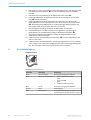
6 Anschlussbelegung
Systemanschluss
Pin-Belegung Systemanschluss
Aderfarbe Bedeutung Bemerkung
Braun 24 V DC Eingang Spannungsversorgung des TWINOX4
Weiß Multifunktionsanschluss
•
Ansc
hlus
s der Rücksetztaste
Oder:
•
Anschluss EDM
Oder:
•
0 V DC (keine Funktion aktiv)
Blau 0 V DC Spannungsversorgung des TWINOX4
Schwarz OSSD Schaltausgang
Grau Funktionserde Um die EMV-Anforderungen zu erfüllen, muss
die Funk
tionserde (FE) angeschlossen werden.
MONTAGEANLEITUNG
6
M O N T A G E A N L E I T U N G | TWINOX4 8022846/11KJ/2018-10-22 | SICK
Irrtümer und Änderungen vorbehalten

A
!
!
!
!
!
!
420 mm
300 mm
&
"
§
$
%
B
!
C
$
$
!
!
§
!
%
!
"
D
"
%
§
&
/
/
&
$
!
MONTAGEANLEITUNG
8022846/11KJ/2018-10-22 | SICK M O N T A G E A N L E I T U N G | TWINOX4
7
Irrtümer und Änderungen vorbehalten


All rights reserved. Subject to change without notice.
1 Safety information
DANGER
Ha
zard due to lack of effectiveness of the protective device
In the case of non-compliance, it is possible that the dangerous state of the machine
may not be stopped or not stopped in a timely manner.
b
Please observe the safety notes provided.
The safety light curtain is not suitable for the following applications, among others:
•
Out
door
s
•
Underwater
•
In explosion-hazardous areas
•
In environments with increased levels of ionizing radiation
•
At altitudes over 3,000 m above sea level
A fuse rated maximum 4 A shall be installed in the isolated 24 V DC power supply cir‐
cuit to the device in order to limit the available current.
For more information about how to work with the protective device, refer to the machin‐
ery documentation or the operating instructions for the protective device. You can call
up the EU declaration of conformity and the current operating instructions for the pro‐
tective device by entering the part number in the search field at www.sick.com (part
number: see the type label entry in the “Ident. no.” field).
2 Twin stick
The safety light curtain consists of 2 small identical twin sticks. Each twin stick con‐
tains bo
th the sender as well as the receiver unit.
3 Status indicators
Complete overview of the LED statuses and their meanings: see operating instructions.
Display of the twin stick
P
osit
ion of LEDs:
A
INSTALLATION INSTRUCTIONS
8022846/11KJ/2018-10-22 | SICK I N S T A L L A T I O N I N S T R U C T I O N S | TWINOX4
9
Subject to change without notice

Meaning of LEDs
Position LED Display Comment
!
OUT
O Gr
een
O
Red
LED lights up green when protective field is free
(OS
SD on).
LED lights up red when protective field is inter‐
rupted (OSSD off).
"
EDM
O Orange
Ext
ernal device monitoring configured.
Ö Orange
F
or the configuration of EDM at the first OSSD sta‐
tus c
hange, the safety light curtain expects the
change from 24 V to 0 V at the multifunctional
input.
Or:
In combination with the ERR-LED Ö red: External
device monitoring reports defective contactor
§
COM
O White
Ext
ernal communication active (e.g. for service)
Ö White
N
o optical communication to another twin stick .
Or:
F
eedbac
k when deactivating configuration.
$
RES
O Or
ange
R
eset configured.
Ö Orange
R
eset configured.
Or:
In combinat
ion with ERR-LED Ö red and EDM-LED
Ö orange: error with configuration or cabling.
%
ERR
O Red
Protective field interrupted.
Ö Red
Er
ror.
&
1, 2, 3, 4, 5
O Blue
Indication of the alignment quality.
Ö Blue In combination with ERR-LED Ö red: dis
play of an
error.
o LED of
f. Ö
LED flashes. O LED illuminates.
The OUT LED (!) is mounted in mult
iple locations and can light up red or green. It is
only labeled OUT in two locations on the safety light curtain.
4 System connection
Overview
T
he s
afety light curtain has a 10 m system connection with an open ended cable.
Mounting: B
!
System connection
INSTALLATION INSTRUCTIONS
10
I N S T A L L A T I O N I N S T R U C T I O N S | TWINOX4 8022846/11KJ/2018-10-22 | SICK
Subject to change without notice

5 Mounting
CAUTION
To consider dur
ing mounting:
b
Mount the twin sticks on a level surface.
b
When mounting, make sure that the safety light curtain is aligned correctly. The
two housings of the twin sticks must be located exactly opposite one another.
b
Take appropriate measures for vibration damping if shock specifications exceed
the values in the data sheet section.
b
When mounting, observe the minimum distance of the system.
b
Then, mount the safety light curtain such that it is not possible to reach over,
under or to stand behind the safety light curtain, and that the light curtain cannot
be repositioned.
Figure 1: With correct mounting (above), the standing behind, reaching under and reaching
ov
er errors (below) must be ruled out.
5.1 Mounting the TWINOX4 bracket
TWINOX4 bracket: C
!
4 x M5x25 fixing screws with ball socket and spacer seal
"
Bracket seal
§
Bracket base
$
Spacer with spacer seal
%
Cable gland
Mounting: D
Approach
1.
Unscr
ew the cable gland from the bracket base (!).
2.
Feed the cable through the rectangular opening of the seal ("). Make sure the
seal with the protruding edge is facing the bracket base.
3. Feed the cable through the bracket base from the inside to the outside and then
through the cable gland (§) until the bracket is lying firmly against the TWINOX4.
4.
Clamp the cable into the strain relief in the bracket base ($).
INSTALLATION INSTRUCTIONS
8022846/11KJ/2018-10-22 | SICK I N S T A L L A T I O N I N S T R U C T I O N S | TWINOX4
11
Subject to change without notice

5. Position the TWINOX4 bracket up against the rear of the twin stick and align the
seal (
%) correctly.
6. Screw on the TWINOX4 bracket using 2 M5 screws with ball socket and spacer
seal and using a maximum tightening torque of 4 Nm (&). Tighten the screws
equally until the seals lie flush. Make sure the seals do not slip while doing so.
7. Screw in the cable gland until it is flush with the bracket base.
8. Mount the spacers onto the bracket base using 2 M5 screws with ball socket and
spacer seal until they are flush with the bracket base (/).
9. Mount the entire bracket with TWINOX4 in the desired position with the help of the
spacer.
10.
Loosen the 2 M5 screws on the spacers slightly (/) and align the TWINOX4 at a
maximum angle of ±2°.
11. Tighten the 2 M5 screws on the spacers using a maximum tightening torque of
4 Nm. Tighten the screws equally until the seals lie flush. Make sure the seals do
not slip while doing so.
6 Pin assignment
System connection
System connection pin assignment
Wire color Meaning Comment
Brown 24 V DC input Voltage supply of the TWINOX4
White Multifunctional connec‐
tion
•
C
onnec
tion of the reset button
Or:
•
EDM connection
Or:
•
0 V DC (no function active)
Blue 0 V DC Voltage supply of the TWINOX4
Black OSSD Switching output
Gray Functional earth To fulfill the EMC requirements, the functional
ear
th (FE) must be connected.
INSTALLATION INSTRUCTIONS
12
I N S T A L L A T I O N I N S T R U C T I O N S | TWINOX4 8022846/11KJ/2018-10-22 | SICK
Subject to change without notice

A
!
!
!
!
!
!
420 mm
300 mm
&
"
§
$
%
B
!
C
$
$
!
!
§
!
%
!
"
D
"
%
§
&
/
/
&
$
!
INSTALLATION INSTRUCTIONS
8022846/11KJ/2018-10-22 | SICK I N S T A L L A T I O N I N S T R U C T I O N S | TWINOX4
13
Subject to change without notice

Further locations at www.sick.com
Australia
Phone +61 (3) 9457 0600
1800 33 48 02 – tollfree
E-Mail [email protected]
Austria
Phone +43 (0) 2236 62288-0
E-Mail of[email protected]
Belgium/Luxembourg
Phone +32 (0) 2 466 55 66
E-Mail [email protected]
Brazil
Phone +55 11 3215-4900
E-Mail [email protected]
Canada
Phone +1 905.771.1444
E-Mail [email protected]
Czech Republic
Phone +420 2 57 91 18 50
E-Mail [email protected]
Chile
Phone +56 (2) 2274 7430
E-Mail [email protected]
China
Phone +86 20 2882 3600
E-Mail info.c[email protected]
Denmark
Phone +45 45 82 64 00
E-Mail [email protected]
Finland
Phone +358-9-25 15 800
E-Mail [email protected]
France
Phone +33 1 64 62 35 00
E-Mail [email protected]
Germany
Phone +49 (0) 2 11 53 01
E-Mail [email protected]
Hong Kong
Phone +852 2153 6300
E-Mail [email protected]
Hungary
Phone +36 1 371 2680
E-Mail ertek[email protected]
India
Phone +91-22-6119 8900
E-Mail info@sick-india.com
Israel
Phone +972-4-6881000
E-Mail [email protected]
Italy
Phone +39 02 27 43 41
E-Mail [email protected]
Japan
Phone +81 3 5309 2112
E-Mail suppor[email protected]
Malaysia
Phone +603-8080 7425
E-Mail enquiry.m[email protected]
Mexico
Phone +52 (472) 748 9451
E-Mail [email protected]
Netherlands
Phone +31 (0) 30 229 25 44
E-Mail [email protected]
New Zealand
Phone +64 9 415 0459
0800 222 278 – tollfree
E-Mail [email protected]
Norway
Phone +47 67 81 50 00
E-Mail [email protected]
Poland
Phone +48 22 539 41 00
E-Mail [email protected]
Romania
Phone +40 356-17 11 20
E-Mail [email protected]
Russia
Phone +7 495 283 09 90
E-Mail [email protected]
Singapore
Phone +65 6744 3732
E-Mail [email protected]
Slovakia
Phone +421 482 901 201
E-Mail [email protected]
Slovenia
Phone +386 591 78849
E-Mail of[email protected]
South Africa
Phone +27 (0)11 472 3733
E-Mail info@sickautomation.co.za
South Korea
Phone +82 2 786 6321
E-Mail info@sickkorea.net
Spain
Phone +34 93 480 31 00
E-Mail [email protected]
Sweden
Phone +46 10 110 10 00
E-Mail [email protected]
Switzerland
Phone +41 41 619 29 39
E-Mail [email protected]
Taiwan
Phone +886-2-2375-6288
E-Mail [email protected]
Thailand
Phone +66 2 645 0009
E-Mail [email protected]
Turkey
Phone +90 (216) 528 50 00
E-Mail [email protected]
United Arab Emirates
Phone +971 (0) 4 88 65 878
E-Mail [email protected]
United Kingdom
Phone +44 (0)17278 31121
E-Mail [email protected]
USA
Phone +1 800.325.7425
E-Mail [email protected]
Vietnam
Phone +65 6744 3732
E-Mail [email protected]
SICK AG | Waldkirch | Germany | www.sick.com
8022846/11KJ/2018-10-22/de, en
-
 1
1
-
 2
2
-
 3
3
-
 4
4
-
 5
5
-
 6
6
-
 7
7
-
 8
8
-
 9
9
-
 10
10
-
 11
11
-
 12
12
-
 13
13
-
 14
14


in anderen Sprachen
- English: SICK TWINOX4
Verwandte Artikel
-
SICK Wichtige Hinweise Important Information Bedienungsanleitung
-
-
-
-
-
-
-
-
-