GSS AR 5201 Assembly Instructions Manual
- Kategorie
- TV-Signalverstärker
- Typ
- Assembly Instructions Manual

Deutsch
English
GSS
Grundig SAT Systems GmbH
Beuthener Straße 43
D-90471 Nuernberg
Telefon: +49 (0) 911 / 703 8877
Fax: +49 (0) 911 / 703 9210
Email: [email protected]
Internet: http://www.gss.de
CLASS
KLASSE
AR 5201
AR 5301
AR 5401
Hausanschlussverstärker
CATV distribution amplifier

- 2 - AR 5201, 5301, 5401
1 Wichtige informationen
Erden Sie die SAT-Empfangsanlage gemäß den rele-
vanten Vorschriften.
Die Normen EN/DIN EN 50083
bzw. IEC/EN/DIN EN 60728 müssen eingehalten
werden.
Führen Sie Installations- und Servicearbeiten nicht
bei Gewittern durch.
Montage, Installation und Service sind von autori-
sierten Elektrofachkräften, die für den Aufbau von
Antennenanlagen ausgebildet sind, durchzuführen.
Beachten Sie die relevanten, nationalen Normen,
Vorschriften und Richtlinien zur Installation und
zum Betrieb von Antennenanlagen.
Vermeiden Sie Kurzschlüsse!
Schäden durch fehlerhaften Anschluss und/oder
unsachgemäße Handhabung sind von jeglicher Haf-
tung ausgeschlossen.
Um die Störstrahlsicherheit des Verstärkers zu ga-
rantieren, muss der Verstärkerdeckel nach dem Öff-
nen wieder fest verschraubt werden!
Umgebungstemperatur Die Umgebungstemperatur
darf den Bereich von 0°C bis +50°C nicht über-
schreiten.
Bedingungen zur Sicherstellung der elektromagne-
tischen Verträglichkeit (EMV): Alle Abdeckungen
und Schrauben müssen fest montiert und angezo-
gen sein, Kontaktfedern dürfen nicht oxidiert oder
verbogen sein.
2 allgemeines
Lieferbares Zubehör
Siehe Webseite "http://www.gss.de"
Verwendete Symbole
Wichtiger Hinweis
Gefährdung durch elektrischen Schlag
• Durchführen von Arbeiten
1 important information
Earth the SAT receiver system in accordance
with the relevant guidelines. The standards
EN/DIN EN 50083 resp. IEC/EN/DIN EN 60728
must be observed.
Do not perform installation and service work during
thunderstorms.
Assembly, installation and servicing should be car-
ried out by authorised electricians, who are skilled
in constructing antenna systems.
Observe the relevant national standards, regula-
tions and guidelines on the installation and opera-
tion of antenna systems.
Avoid short circuits!
No liability is accepted for damage caused by faulty
connections or inappropriate handling of the device.
To guarantee the EMC protection of the amplifier
the lid must be bold tight again after opening the
amplifier.
Ambient temperature The ambient temperature
should not exceed a range of 0 C to + 50°C (32°F
to 122°F).
Precautions to ensure the electromagnetic com-
pability (EMV): All covers and screws must tightly
be fitted and should be tightly fastened. Contact
springs should not be oxidated or deformed.
2 general
Available accessories
See webseite "http://www.gss.de/en"
Symbols used
Important note
Danger by electrical shock
• Performing works

- 3 - AR 5201, 5301, 5401
3 BeschreiBung
Die AR 5xxx-Serie sind multimediafähige
Hausanschlussverstärker für kleine bis mittel-
große Gebäudeeinheiten. Sie werden zum
Ausgleich der Kabel– und Verteildämpfung
im BK-Hausnetz eingesetzt und haben alle
wichtigen Funktionseinheiten wie Vorwärts-
verstärker, Diplexfilter, Rückkanalverstärker
und die zugehörigen Stellglieder und Dreh-
schalter vollständig auf der Leiterplatte im-
plementiert. Sie benötigen keine weiteren
Zubehörteile zur Inbetriebnahme oder den
Betrieb.
– 1 GHz Technologie
– Vorwärtsweg: 20 bis 40 dB Verstärkung
/ hoher Ausgangspegel
– Dämpfung und Leitungsentzerrung mit-
tels Drehschaltern in 1dB-Stufen einstell-
bar. Grundverstärkungen mit Jumpern
wählbar.
–
Betriebsart Rückkanal 5-65 MHz (RC =
ON) oder VHF Band I (RC = OFF) wählbar
– Rückkanal schaltbar: Aktiv/Passiv/Aus.
– Rückkanalverstärkung schaltbar (ausser
AR 5201) / hohe Aussteuerreserve Klas-
se C oder D nach KDG 1TS140
– All-on-board Technologie: alle Funktio-
nen ohne zusätzliche Module vorhanden
– Alle HF-Anschlüsse sind handmontierte,
hochwertige F-Buchsen.
– -20 dB Testbuchsen am Ein– und Aus-
gang des Verstärkers
– Exzellenter ESD– und Überspannungs-
schutz
– Niedriger Energiebedarf durch hocheffi-
ziente Schaltnetzteile für 190-264 VAC,
50/60 Hz Netzanschluss.
3 Description
The AR 5xxx Series is a low noise coaxial
House Distribution Amplifier, for use in small-
er to medium CATV distribution networks in
multi dwelling houses and share a modu-
lar design with return path all-on-board for
easy setting and installation Rotary switches
and jumpers provide for readable, easy
and reproducible setting of attenuation and
equalization, maintaining a non-breakable
signal path down- and upstream to avoid
down-time.
– 1 GHz technology
– Downstream 20 to 40 dB amplification /
high output level
– Adjustable attenuation and equalization
settings in 1 dB steps using rotary switch-
es and jumpers.
– Switchable VHF Band I (RC = OFF) or
5-65 MHz Return Path (RC = ON)
– Selectable Return Path: On/Off, Active/
Passive.
– Switchable upstream amplification (ex-
cept AR 5201) / high output level
– All-on-board return path technology, all
features available without module.
– All connectors are hand mounted F-con-
nectors female.
– -20 dB input- and output- test connectors
– Extensive ESD- and surge-protection
– Low power consumption due to high ef-
ficiently switching power supply for 190-
264 VAC, 50/60 Hz mains connection

- 4 - AR 5201, 5301, 5401
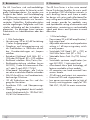
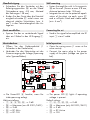
Blockschaltplan
HP HP
LP LP
=
≈
Attenuator
0/6 dB
jumper
Attenuator*
0/6 dB
jumper
*nur AR5301/5401
*only AR5301/5401
Attenuator
0-15 dB
Rotary switch
RC gain
Equalizer
0/3/7 dB
jumper
Equalizer
0/3/6/9 dB
jumper
Input
RC output
Test 1, -20 dB
bidirectional
Diplex filter
switchable
Diplex filter
switchable
Return path
ON/OFF/active/passiv
Return path
Test 2, -20 dB
unidirectional
SM Power supply
190-264 VAC Mains
Output
RC input
Equalizer
0-15 dB
Rotary switch
Attenuator
0-15 dB
Rotary switch
Input stage Interstage Output stages
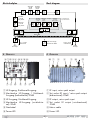
4 ÜBersicht
2 4 3 51 @
!7 8 0%9 6 $#
1 HF-Eingang, Rückkanal-Ausgang.
2 Messbuchse HF-Eingang / Rückkanal-
Ausgang (bidirektional) -20dB
3 HF-Ausgang, Rückkanal-Eingang
4 Messbuchse HF-Ausgang (uni-direktio-
nal) -20dB
5 Netzkabel
6 Power-LED
Block diagram
4 overvieW
^ 1 42 3 &^
1 RF input, return path output.
2 Test socket RF input / return path output
(bidirectional) -20dB
3 RF output, return path input
4 Test socket RF output (uni-directional)
-20dB
5 Mains cable
6 Power LED

- 5 - AR 5201, 5301, 5401
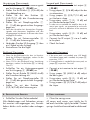
7 Input attenuator
Rotary switch 0…15 dB
8 Input slope
Rotary switch 0…15 dB
9 Interstage attenuator
Jumper 0/6 dB
0 Interstage slope
Jumpers 0/3/7/10 dB
! Return path on/off
Jumper "RC ON"/"RC OFF"
@ Return path passive/active
Jumper "RC Passiv"/"RC Active"
# Return path input attenuator
Rotary switch 0…15 dB
$ Return path gain
Jumper Maximum/-6 dB
(only AR 5301/5401)
% Return path interstage slope
Jumpers 0/3/6/9 dB
^ Fixing points, distance 158 mm,
screw diameters max. 4.8 mm
& Grounding screw
5. mounting
Observe the information on page 2!
Mount the amplifier...
– Horizontal, free on the wall and so that
the convection cooling of the unit is not
compromised.
– On non-flammable material (concrete or
brick wall)
– In a dust free environment, protected
against moisture and fluid (drop– and
spray water).
– Not in a spot with direct sun radiation
(e.g. on the roof)
– Not directly along with heat sources
(e.g. heating room)
– In compliance with the highest allowed
working temperature (measured at the
airflow under the amplifier)
7 Pegelsteller Eingang
Drehschalter 0…15 dB
8 Entzerrung Eingang
Drehschalter 0…15 dB
9 Pegelsteller Interstage
Brücke 0/6 dB
0 Entzerrung Interstage
Brücken 0/3/7/10 dB
! Rückkanal ein/aus
Brücke "RC ON"/"RC OFF"
@ Rückkanal passiv/aktiv
Brücke "RC Passiv"/"RC Active"
# Pegelsteller Eingang Rückkanal
Drehschalter 0…15 dB
$ Verstärkung Rückkanal
Brücke Maximum/-6 dB
(nur AR 5301/5401)
% Entzerrung Interstage Rückkanal
Brücken 0/3/6/9 dB
^ Befestigungspunkte, Abstand 158 mm,
max. Schraubendurchmesser 4,8 mm
& Potentialausgleichschraube
5. montage
Beachten Sie die Informationen auf Seite 2!
Montieren Sie den Verstärker
– Waagerecht, frei an der Wand und so,
dass die Konvektionskühlung des Ver-
stärkers nicht behindert wird
– Auf schwer entflammbarem Untergrund
(Mauer)
– In staubfreier Umgebung, geschützt ge-
gen Feuchtigkeit und Nässe (Tropf– und
Spritzwasser)
– Nicht an einen Ort mit direkter Sonnen-
einstrahlung (z.B. Dachboden)
– Nicht in unmittelbarer Nähe von Wär-
mequellen (z.B. Heizraum)
– Unter Berücksichtigung der maximal zu-
lässigen Betriebstemperatur (gemessen
am Luftstrom unter dem Verstärker)

Wandbefestigung
• Schrauben Sie den Verstärker mit den
Befestigungspunkten ^ an die Wand
(Schrauben-ø max. 4.8 mm, Abstand
der Bohrungen 158 mm).
• Binden Sie das Gerät über die Potential
ausgleichschraube & mittels eines me-
chanisch stabilen Schutzleiters (min. 4
mm
2
) in den Potentialausgleich der An-
lage ein.
Gerät anschließen
• Speisen Sie das zu verstärkende Signal
über ein F-Kabel in den HF-Eingang 1
ein.
Inbetriebnahme
• Öffnen Sie den Gehäusedeckel (1
Schraube in der Deckelmitte).
• Verbinden Sie den Netzstecker mit der
Stromversorgung der Anlage (Spannung
siehe Typenaufkleber).
0 8
4
12
ATT
ATT
ATT
0…15 dB
0…15 dB
0…15 dB
EQ
10 dB
Gain switch is not available in AR 5201
3 dB
0 dB
-6 dB
MAX
6
9
0
736
000
EQ
EQ
RC
ON
RC
OFF
RC
Passiv
RC
Active
IN
Test
-20 dB
Test
-20 dB
OUT
GAIN
PWR
DOWNSTREAM >>
<< UPSTREAM
0 8
4
12
0 8
4
12
%
$
#
!
1 2 4 3
@
7
8
0
9
6
–> Die Power-LED 6 leuchtet, wenn Be-
triebsspannung anliegt.
Werkseinstellung:
– 7, 8, 9, 0, #, –> 0 dB
– $ –> Maximum (nur AR 5301/5401)
– % –> 3 dB
– @ –> RC Aktiv
– ! –> RC ON
Wall mounting
• Fasten the amplifier with its fixing points
^ on the wall. (Screws ø max. 4.8 mm,
distance between holes 158 mm).
• Integrate the set into the potential equali-
sation of the plant via earth screw &
and a sufficient fitted and stable cable
(min. 4 mm
2
).
Connecting the set
• Feed in the signal to be amplified into RF
input 1 via a F cable.
Initial operation
• Open the casing cover (1 screw at the
cover centre).
• Connect the mains plug to the power
supply of the plant (voltage see type la-
bel).
–> The power LED 6 lights if operating
voltage is present.
Default settings:
– 7, 8, 9, 0, #, –> 0 dB
– $ –> Maximum (only AR 5301/5401)
– % –> 3 dB
– @ –> RC Active
– ! –> ON

Forward path (Downstream):
• Connect a test receiver to test output 4
(-20 dB!).
• Using jumper 9 (0/6 dB) adjust the ba-
sic attenuation.
• Using jumpers 0 (0/3/7/10 dB) ad-
just the basic slope.
• Using rotary switch 7 (0…15 dB) ad-
just the desired output level.
–> In order not to overload the amplifier due to dy-
namic input signals, we recommend to set the out-
put level a minimum 6 dB below of the maximum
level.
• Using rotary switch 8 (0…15 dB) ad-
just the desired slope.
• Connect the RF output 3 via a F cable
to the plant.
• Check the levels.
Return path (Upstream):
–> If the return path is not needed, resp. VHF band I
in the downstream path is needed, set jumper !
to position "OFF"!
–> If no amplification is needed for the return path, set
jumper @ to position "Passive"!
• Connect a test receiver to test output 2
(-20 dB!).
• Using jumper $ (MAX/–6 dB) adjust
the basic gain.
• Using rotary switch # (0…15 dB) ad-
just the desired output level.
• Using jumpers % (0/3/6/9 dB) adjust
the slope.
6. final proceDures
• Close the casing cover.
All covers and screws must tightly be fit-
ted and should be tightly fastened. Contact
springs should not be oxidized or deformed.
Vorwärtsweg (Downstream):
• Schließen Sie ein Antennenmessgerät
am Test-Ausgang 4 (-20 dB!) an.
• Stellen Sie mit Brücke 9 (0/6 dB) die
Grunddämpfung ein.
• Stellen Sie mit den Brücken 0
(0/3/7/10 dB) die Grundentzerrung
(Linearität) ein.
• Stellen Sie mit Dämpfungssteller 7
(0…15 dB) den gewünschten Ausgangs-
pegel ein.
–> Damit der Verstärker bei dynamischen Eingangs-
signalen nicht übersteuert, empfehlen wird, den
Ausgangspegel mindestens 6 dB unter dem Maxi-
malpegel einzustellen.
• Stellen Sie mit Entzerrungssteller 8
(0…15 dB) die Entzerrung ein.
• Verbinden Sie den HF-Ausgang 3 über
ein F-Kabel mit der Anlage.
• Kontrollieren Sie die Pegel.
Rückkanal (Upstream):
–> Wenn Sie den Rückkanal nicht, bzw. im Vorwärts-
kanal das VHF-Band I benötigen, stecken Sie die
Brücke ! in Stellung "OFF"!
–> Wenn Sie für den Rückkanal keine Verstärkung
benötigen, stecken Sie die Brücke @ in Stellung
"Passiv"!
• Schließen Sie ein Antennenmessgerät
am Test-Ausgang 2 (-20 dB!) an.
• Stellen Sie mit Brücke $ (MAX/–6 dB)
die Grundverstärkung ein.
• Stellen Sie mit Dämpfungssteller #
(0…15 dB) den gewünschten Ausgangs-
pegel ein.
• Stellen Sie mit den Brücken %
(0/3/6/9 dB) die Entzerrung ein.
6. aBschliessenDe arBeiten
• Schließen Sie den Gehäusedeckel.
Alle Abdeckungen und Schrauben müssen
fest montiert und angezogen sein, Kontakt-
federn dürfen nicht oxidiert oder verbogen
sein.

Änderungen vorbehalten. Technische Angaben ohne Gewähr. © by GSS GmbH 16082013
Alterations reserved. Technical data E. & O.E.
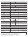
7 technische Daten 7 technical Data
AR 5201 AR 5301 AR 5401
Frequenzbereich Frequency range
Rückkanal (RP) ein [MHz] 85-1006 [MHz] Return path (RP) on
Rückkanal (RP) aus [MHz] 47-1006 [MHz] Return path (RP) off
Rückkanal (RP) [MHz] 5-65 [MHz] Return path
Verstärkung vorwärts Gain forward
Verstärkung @ 1006 MHz [dB] 20 30 40 [dB] Gain @ 1006 MHz
Dämpfung Eingang; [1dB-Schritte] 0…15 [1dB steps] Input attenuator
Entzerrung Eingang; [1dB-Schritte] 0…15 [1dB steps] Input slope
Dämpfung Interstage [dB] 0/6 [dB] Interstage attenuator
Entzerrung Interstage [dB] 0/3/7/10 [dB] Interstage slope
Verstärkung Rückkanal Gain return path
Verstärkung @ 60 MHz (-6dB/MAX) [dB]
–/20 22/28 26/32 [dB] Gain @ 60 MHz (-6dB/MAX)
Dämpfung Eingang [1dB-Schritte] 0…15 [1dB steps] Input attenuator
Entzerrung Interstage [dB] 0/3/6/9 [dB] Interstage slope
Linearität Amplitudenfrequenzgang Linearity frequency response
@ 47...1006 MHz [dB] ± 1.5 [dB] @ 47...1006 MHz
@ 85...1006 MHz [dB] ± 1.0 [dB] @ 85...1006 MHz
@ 5...65 MHz (RP) [dB] ± 1.0 [dB] @ 5...65 MHz (RP)
Rauschmaß Noise figure
Vorwärts (RP off) [dB] < 7.0 [dB] Forward (RP off
Rückwärts (RP active) [dB] – < 5.5 [dB] Return path (RP active)
Rückflussdämpfung @40 MHz, -1,5 dB/Oktave Return loss @40 MHz, -1.5 dB/Oktave
Vorwärts [dB] >18 [dB] Forward
Rückwärts [dB] >18 [dB] Return path
Ausgangspegel vorwärts Output level forward
CSO Cenelec 42 ch. 862 MHz,
Slope 0/7 dB
[dBμV]
98/100 103/105 107/109
CSO Cenelec 42 ch. 862 MHz,
[dBμV]
Slope 0/7 dB
CTB Cenelec 42 ch. 862 MHz,
Slope 0/7 dB
[dBμV]
98/100 103/105 108/109
CTB Cenelec 42 ch. 862 MHz,
[dBμV]
Slope 0/7 dB
Maximaler Ausgangspegel rückwärts Maximum output level return path
IMA2, >60 dB
[dBμV]
96 96 98
[dBμV]
IMA2, >60 dB
IMA3, >60 dB
[dBμV]
117 117 119
[dBμV]
IMA3, >60 dB
16 QAM (KDG1TS140 - C)
[dBμV]
120 120 –
[dBμV]
16 QAM (KDG1TS140 - C)
16 QAM (KDG1TS140 - D)
[dBμV]
– – 120
[dBμV]
16 QAM (KDG1TS140 - D)
HF-Anschlüsse (F-Buchse 75Ω) RF connectors (F-female 75Ω)
Eingang/Ausgang 1/1 Input/Output
Messbuchse Eingang (bi-direktional) [dB] –20 [dB] Test point input (bi-directional)
Messbuchse Ausgang (uni-direktional)
[dB]
–20 [dB] Test point output (uni-directional)
Allgemeines General
Versorgungsspannung (50-60 Hz) [V] 190-264 [V] Power supply voltage (50-60 Hz)
Leistungsaufnahme [W] < 9 [W] Power consumption
Betriebstemperaturbereich [°C] -25…+55 [°C] Operating temperature
Schutzart II Protection class
Schutzklasse [IP] 20 [IP] Housing protection degree
Abmessungen B x H x T [mm] 170 x 100 x 65 [mm] Dimensions W x H x D
Gewicht [kg] 2.0 [kg] Weight
Service:
Phone: +49 (0) 911 / 703 2221 • Fax: +49 (0) 911 / 703 2326 • Email: ser[email protected]
Grundig SAT Systems GmbH • Beuthener Straße 43 • D-90471 Nürnberg
-
 1
1
-
 2
2
-
 3
3
-
 4
4
-
 5
5
-
 6
6
-
 7
7
-
 8
8


GSS AR 5201 Assembly Instructions Manual
- Kategorie
- TV-Signalverstärker
- Typ
- Assembly Instructions Manual
in anderen Sprachen
- English: GSS AR 5201
Verwandte Artikel
Andere Dokumente
-
TechniSat TECHNITOP HAV 38-2 Bedienungsanleitung
-
Triax GHV 920 Benutzerhandbuch
-
Axing Premium-line BVS 14-69 Operation Instructions
-
-
Kathrein VOS 137/RA Spezifikation
-
-
POLYTRON HV 36122 Bedienungsanleitung
-
Axing premium-line Series Operation Instructions
-
Axing BVS 13-68 CATV amplifier 30 dB Operation Instructions
-
Axing BVS 20-69 Operation Instructions