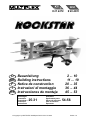
MULTIPLEX BK Rockstar Bedienungsanleitung
- Kategorie
- Ferngesteuertes Spielzeug
- Typ
- Bedienungsanleitung
Dieses Handbuch ist auch geeignet für

# 26 4278
Bauanleitung 2 ... 10
Building instructions 11 ... 19
Notice de construction 20 ... 35
Instruzioni di montaggio 36 ... 44
Instrucciones de montaje 45 ... 53
54-56
D
F
GB
I
ES
© Copyright by MUL
TIPLEX Modellsport GmbH & Co. KG 2015 Version 1.0
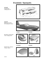
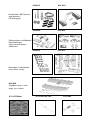
Ersatzteile
Replacement parts
Pièces de rechanges
Parti di ricambio
Repuestos
Abbildungen
Illustrations
Illustrations
Illnstrazioni
Iiustraciónes
... 25-31
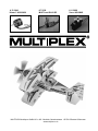
RR
# 21 4278

Seite 2
Sicherheitshinweise für MULTIPLEX-Flugmodelle
Das Modell ist KEIN SPIELZEUG im üblichen Sinne.
Mit Inbetriebnahme des Modells erklärt der Betreiber, dass er den Inhalt der Betriebsanleitung, besonders zu Sicher-
heitshinweisen, Wartungsarbeiten, Betriebsbeschränkungen und Mängel kennt und inhaltlich nachvollziehen kann.
Dieses Modell darf nicht von Kindern unter 14 Jahren betrieben werden. Betreiben Minderjährige das Modell unter der
Aufsicht eines, im Sinne des Gesetzes, fürsorgepfl ichtigen und sachkundigen Erwachsenen, ist dieser für die Umsetzung
der Hinweise der BETRIEBSANLEITUNG verantwortlich.
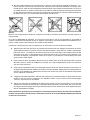
DAS MODELL UND DAZUGEHÖRIGES ZUBEHÖR MUSS VON KINDERN UNTER 3 JAHREN FERNGEHALTEN
WERDEN! ABNEHMBARE KLEINTEILE DES MODELLS KÖNNEN VON KINDERN UNTER 3 JAHREN VERSCHLUCKT
WERDEN. ERSTICKUNGSGEFAHR!
Beim Betrieb des Modells müssen alle Warnhinweise der BETRIEBSANLEITUNG beachtet werden. Die Multiplex Mo-
dellsport GmbH & Co. KG ist nicht haftungspfl ichtig für Verluste und Beschädigungen jeder Art, die als Folge falschen
Betriebes oder Missbrauches dieses Produktes, einschließlich der dazu benötigten Zubehörteile entstehen. Dies beinhaltet
direkte, indirekte, beabsichtigte und unabsichtliche Verluste und Beschädigungen und jede Form von Folge-schäden.
Jeder Sicherheitshinweis dieser Anleitung muss unbedingt befolgt werden und trägt unmittelbar zum sicheren Betrieb
Ihres Modells bei. Benutzen Sie Ihr Modell mit Verstand und Vorsicht, und es wird Ihnen und Ihren Zuschauern viel
Spaß bereiten, ohne eine Gefahr darzustellen. Wenn Sie Ihr Modell nicht verantwortungsbewusst betreiben, kann dies
zu erheblichen Sachbeschädigungen und schwerwiegenden Verletzungen führen. Sie alleine sind dafür verantwortlich,
dass die Betriebsanleitungen befolgt und die Sicherheitshinweise in die Tat umgesetzt werden.
Bestimmungsgemäße Verwendung
Das Modell darf ausschließlich im Hobbybereich verwendet werden. Jede weitere Verwendung darüber hinaus ist nicht
erlaubt. Für Schäden oder Verletzungen an Menschen und Tieren aller Art haftet ausschließlich der Betreiber des Modells
und nicht der Hersteller.
Zum Betrieb des Modells darf nur das von uns empfohlene Zubehör verwendet werden. Die empfohlenen Komponenten
sind erprobt und auf eine sichere Funktion passend zum Modell abgestimmt. Werden andere Komponenten verwendet
oder das Modell verändert, erlöschen alle Ansprüche an den Hersteller bzw. den Vertreiber.
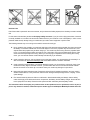
Um das Risiko beim Betrieb des Modells möglichst gering zu halten, beachten Sie folgende Punkte:
l Das Modell wird über eine Funkfernsteuerung gelenkt. Keine Funkfernsteuerung ist sicher vor Funkstörungen.
Solche Störungen können dazu führen, dass Sie zeitweise die Kontrolle über Ihr Modell verlieren. Deshalb müs-
sen Sie beim Betrieb Ihres Modells zur Vermeidung von Kollisionen immer auf große Sicherheitsräume in allen
Richtungen achten. Schon beim kleinsten Anzeichen von Funkstörungen müssen Sie den Betrieb Ihres Modells
einstellen!
l Sie dürfen Ihr Modell erst in Betrieb nehmen, nachdem Sie einen kompletten Funktionstest und einen Reichwei-
tentest, gemäß der Anleitung Ihrer Fernsteuerung, erfolgreich ausgeführt haben.
l Das Modell darf nur bei guten Sichtverhältnissen gefl ogen werden. Fliegen Sie nicht in Richtung Sonne, um
nicht geblendet zu werden, oder bei anderen schwierigen Lichtverhältnissen.
l Ein Modell darf nicht unter Alkohol-Einfl uss oder Einfl uss von anderen Rauschmitteln oder Medikamenten be-
trieben werden, die das Wahrnehmungs- und Reaktionsvermögen beeinträchtigen.
l Fliegen Sie nur bei Wind- und Wetterverhältnissen, bei denen Sie das Modell sicher beherrschen können. Be-
rücksichtigen Sie auch bei schwachem Wind, dass sich Wirbel an Objekten bilden, die auf das Modell Einfl uss
nehmen können.
l Fliegen Sie nie an Orten, an denen Sie andere oder sich selbst gefährden können, wie z.B. Wohngebiete, Über-
landleitungen, Straßen und Bahngleise.
l Niemals auf Personen und Tiere zufl iegen. Anderen Leuten dicht über die Köpfe zu fl iegen ist kein Zeichen für
wirkliches Können, sondern setzt andere Leute nur ein unnötiges Risiko aus. Weisen Sie auch andere Piloten
in unser aller Interesse auf diese Tatsache hin. Fliegen Sie immer so, dass weder Sie noch andere in Gefahr
kommen. Denken Sie immer daran, dass auch die allerbeste Fernsteuerung jederzeit gestört werden kann. Auch
langjährige, unfallfreie Flugpraxis ist keine Garantie für die nächste Flugminute.
D

Seite 3
Restrisiken
Auch wenn das Modell vorschriftsmäßig und unter Beachtung aller Sicherheitsaspekten betrieben wird, besteht immer
ein gewisses Restrisiko.
Eine Haftpfl ichtversicherung ist daher obligatorisch. Falls Sie in einen Verein oder Verband eintreten, können Sie diese
Versicherung dort abschließen. Achten Sie auf ausreichenden Versicherungsschutz (Modellfl ugzeug mit Antrieb). Halten
Sie Modelle und Fernsteuerung immer absolut in Ordnung.
Folgende Gefahren können im Zusammenhang mit der Bauweise und Ausführung des Modells auftreten:
l Verletzungen durch die Luftschraube: Sobald der Akku angeschlossen ist, ist der Bereich um die Luftschraube
freizuhalten. Beachten Sie auch, dass Gegenstände vor der Luftschraube angesaugt werden können oder Ge-
genstände dahinter weggeblasen werden können. Das Modell kann sich in Bewegung setzen. Richten Sie es
daher immer so aus, dass es sich im Falle eines ungewollten Anlaufen des Motors nicht in Richtung anderer
Personen bewegen kann. Bei Einstellarbeiten, bei denen der Motor läuft oder anlaufen kann, muss das Modell
stets von einem Helfer sicher festgehalten werden.
l Absturz durch Steuerfehler: Kann dem besten Piloten passieren, deshalb nur in sicherer Umgebung fl iegen; ein
zugelassenes Modellfl uggelände und eine entsprechende Versicherung sind unabdingbar.
l Absturz durch technisches Versagen oder unentdeckten Transport- oder Vorschaden. Die sorgfältige Überprüfung
des Modells vor jedem Flug ist ein Muss. Es muss jedoch immer damit gerechnet werden, dass es zu Material-
versagen kommen kann. Niemals an Orten fl iegen, an denen man Anderen Schaden zufügen kann.
l Betriebsgrenzen einhalten. Übermäßig hartes Fliegen schwächt die Struktur und kann entweder zu plötzlichem
Materialversagen führen, oder bei späteren Flügen das Modell aufgrund von „schleichenden“ Folgeschäden
abstürzen lassen.
l Feuergefahr durch Fehlfunktion der Elektronik. Akkus sicher aufbewahren, Sicherheitshinweise der Elektro-
nikkomponenten im Modell, des Akkus und des Ladegerätes beachten, Elektronik vor Wasser schützen. Auf
ausreichende Kühlung bei Regler und Akku achten.
Die Anleitungen unserer Produkte dürfen nicht ohne ausdrückliche Erlaubnis der Multiplex Modellsport GmbH
& Co. KG (in schriftlicher Form) - auch nicht auszugsweise in Print- oder elektronischen Medien reproduziert
und / oder veröffentlicht werden.
D

Seite 4
Machen Sie sich mit dem Bausatz vertraut!
MULTIPLEX – Modellbaukästen unterliegen während der Produktion einer ständigen Materialkontrolle. Wir hoffen, dass
Sie mit dem Baukasteninhalt zufrieden sind. Wir bitten Sie jedoch, alle Teile (nach Stückliste) vor Verwendung zu prü-
fen, da bearbeitete Teile vom Umtausch ausgeschlossen sind. Sollte ein Bauteil einmal nicht in Ordnung sein, sind
wir nach Überprüfung gern zur Nachbesserung oder zum Umtausch bereit. Bitte senden Sie das Teil, bitte ausreichend
frankiert, an unsere Modellbauabteilung und fügen Sie unbedingt den Kaufbeleg und eine kurze Fehlerbeschreibung bei.
Wir arbeiten ständig an der technischen Weiterentwicklung unserer Modelle. Änderungen des Baukasteninhalts in
Form, Maß, Technik, Material und Ausstattung behalten wir uns jederzeit und ohne Ankündigung vor. Bitte haben Sie
Verständnis dafür, dass aus Angaben und Abbildungen dieser Anleitung keine Ansprüche abgeleitet werden können.
Achtung!
Ferngesteuerte Modelle, insbesondere Flugmodelle, sind kein Spielzeug im üblichen Sinne. Ihr Bau und Betrieb
erfordert technisches Verständnis, ein Mindestmaß an handwerklicher Sorgfalt sowie Disziplin und Sicherheits-
bewusstsein. Fehler und Nachlässigkeiten beim Bau und Betrieb können Personen- und Sachschäden zur Folge
haben. Da der Hersteller keinen Einfl uss auf ordnungsgemäßen Zusammenbau, Wartung und Betrieb hat, weisen
wir ausdrücklich auf diese Gefahren hin.
Warnung:
Das Modell hat, wie jedes Flugzeug, statische Grenzen! Sturzfl üge und unsinnige Manöver im Unverstand können zum
Verlust des Modells führen. Beachten Sie: In solchen Fällen gibt es von uns keinen Ersatz. Tasten Sie sich also vorsichtig
an die Grenzen heran. Das Modell ist auf den von uns empfohlenen unseren Antrieb ausgelegt, kann aber nur einwandfrei
gebaut und unbeschädigt den Belastungen standhalten.
Benötigtes Zubehör für das Modell ROCKSTAR :
Zacki ELAPOR 20g VE1 RR+KIT Best.-Nr. 852727
Li-BATT FX 4/1 2600 (M6) RR+KIT Best.-Nr. 157362
Empfänger RX-5 light M-LINK 2,4 GHz RR+KIT Best.-Nr. 55808
Antriebssatz ROCKSTAR KIT Best.-Nr. 332667
Servo HS-82 MG (4x) KIT Best.-Nr. 112088
Verlängerungskabel 15 cm (UNI) (2x) KIT Best.-Nr. 85019
D

Seite 5
Wichtiger Hinweis
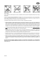
Dieses Modell ist nicht aus Styropor ™! Daher sind Verklebungen mit Weißleim, Polyurethan oder Epoxy nicht möglich.
Diese Kleber haften nur oberfl ächlich und platzen im Ernstfall einfach ab. Verwenden Sie nur Cyanacrylat-/Sekunden-
kleber mittlerer Viskosität, vorzugsweise Zacki -ELAPOR® # 85 2727, der für ELAPOR® Partikelschaum optimierte und
angepasste Sekundenkleber. Bei Verwendung von Zacki-ELAPOR® können Sie auf Kicker oder Aktivator weitgehend
verzichten. Wenn Sie jedoch andere Kleber verwenden, und auf Kicker/Aktivator nicht verzichten können, sprühen Sie
aus gesundheitlichen Gründen nur im Freien. Vorsicht beim Arbeiten mit allen Cyanacrylatklebern. Diese Kleber härten
u.U. in Sekunden, daher nicht mit den Fingern und anderen Körperteilen in Verbindung bringen. Zum Schutz der Augen
unbedingt Schutzbrille tragen! Von Kindern fernhalten! An einigen Stellen ist es auch möglich Heißkleber zu verwenden.
Wir weisen in der Anleitung ggf. darauf hin!
Arbeiten mit Zacki ELAPOR®
Zacki ELAPOR® wurde speziell für die Verklebung für unsere Schaummodelle aus ELAPOR® entwickelt.
Um die Verklebung möglichst optimal zu gestalten, sollten Sie folgende Punkte beachten:
• Vermeiden Sie den Einsatz von Aktivator. Durch ihn wird die Verbindung deutlich geschwächt.
Vor allem bei großfl ächiger Verklebung empfehlen wir, die Teile 24 h trocken zu lassen.
• Aktivator ist lediglich zum punktuellen Fixieren zu verwenden. Sprühen Sie nur wenig Aktivator einseitig auf.
Lassen Sie den Aktivator ca. 30 Sekunden ablüften.
• Für eine optimale Verklebung rauen Sie die Oberfl äche mit einem Schleifpapier (320 er Körnung) an.
Krumm - gibt es eigentlich nicht. Falls mal etwas z.B. beim Transport verbogen wurde, kann es wieder gerichtet
werden. Dabei verhält sich ELAPOR® ähnlich wie Metall. Etwas überbiegen, das Material federt ein Stück zurück
und behält dann aber die Form. Alles hat natürlich auch seine Grenzen - übertreiben Sie also nicht!
Krumm - gibt es schon! Wenn Sie Ihr Modell lackieren wollen, reiben Sie die Oberfl äche leicht mit MPX Primer #
602700 ab, so als wollten Sie das Modell putzen. Die Lackschichten dürfen keinesfalls zu dick oder ungleichmäßig
aufgetragen werden, sonst verzieht sich das Modell. Es wird krumm, schwer und oft sogar unbrauchbar! Mattlacke
bringen optisch das beste Ergebnis.
Technische Daten:
Spannweite: 1050
Länge über alles: 1060
Fluggewicht: 1800
Gesamtfl ächeninhalt: 48dm²
Gesamtfl ächenbelastung: 38g/dm²
Steuerkanäle: 5
RC-Funktionen: Höhenruder, Seitenruder, Querruder, Motor
Flugzeit: 7 min. (4S ~2600Ah)
Hinweis: Bildseiten aus der Mitte der Bauaneitung heraustrennen!

Seite 6
Herzlichen Glückwunsch zu Ihrem neuen MULTIPLEX-
ROCKSTAR!
Zum Bau des Modells benötigen Sie folgendes Werk-
zeug:
2x Zacki-Elapor # 85 2727 (KIT) (1xRR)
1x UHU Por (KIT)
Heißklebepistole (KIT)
mittleren Kreuzschlitzschraubendreher (KIT)
mittleren Schlitzschraubdreher (KIT)
Cuttermesser (KIT)
Spitzzange (KIT)
Inbusschlüssel 1,5 (KIT)
Inbusschlüssel 3 (KIT)
10er Gabelschlüssel (KIT)
2,5mm Bohrer (KIT)
Vor dem Bau:
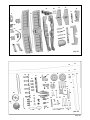
Überprüfen Sie die gelieferten Teile auf Ihre Vollständigkeit
mittels der Stückliste auf Seite 9+10 (pic. 01 & 02).
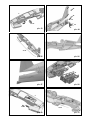
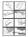
1. Zusammenbau des Rumpfs (KIT)
Klipsen Sie die beiden Teile des Flügelgegenlagers 33 und
34 zusammen und verkleben Sie sie mit Zacki. ! Achtung!
Beim Zusammenkleben /klipsen der Teile kann Klebstoff
herausspritzen. Kleben Sie dann die Canopylock Ver-
schlussklammer 31, das Baldachingegenlager 28 und das
Flügelgegenlager in die rechte Rumpfhälfte 5 ein. Kleben
Sie die beiden Scharnierachsaufnahmen 44 in die Schlitze
der rechten Seitenleitwerkshälfte. Ebenso kleben Sie das
Mutteraufnahme 39 (M5) und das Spornradaufl ager 40 ein.
Abb. 03 + 04
Stecken Sie einen F-Stahldraht 73 durch das Bowdenzug-
rohr 74 und verlegen Sie es in der rechten Rumpfhälfte so,
dass der Bowdenzug den Rumpf hinten verlässt und etwa
30mm übersteht, kleben Sie es fest.
Abb. 05 – 07
Kleben Sie nun noch den vormontierten M-Frame 27 in die
rechte Rumpfhälfte 5 ein.
Abb. 08
In die linke Rumpfhälfte 4 kleben Sie analog zu den vor-
herigen Schritten die Canopylock-Klammer 31 und das
Baldachingegenlager 28 ein. Anschließend wird auch hier
ein Bowdenzugrohr 74 eingeschobenem F-Stahldraht 73
so verlegt, dass das Rohr am Rumpfende etwa 30mm
heraussteht.
Abb. 09 – 11
Stecken Sie nun die beiden Rumpfhälften OHNE Kleber
zusammen und überprüfen Sie den ordnungsgemäßen
Sitz der Teile. Wenn alles passt, tragen Sie Kleber auf und
fügen Sie die Teile exakt zusammen.
Abb. 12 + 13
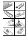
Sie können nach diesem Bauschritt die Pilotenpuppe nach
Ihren Wünschen bemalen.
Beachten Sie bitte, dass sich dunkle Flächen unter der
Kabinenhaube bei Sonneneinstrahlung stark erwärmen
können. An diesen Stellen kann das ELAPOR unter Um-
ständen aufpoppen/Blasen bekommen!
Kleben Sie den Instrumentenbrett-Aufkleber (Dekorbogen)
auf das angeformte Panel im Cockpit. Wenn Sie mit der
Gestaltung Ihres Cockpits zufrieden sind, kleben Sie die
Kabinenhaube 26 mit UHU Por auf den Rumpf.
Abb. 14
Kleben Sie die vier Magnete 58 zur Befestigung der Mo-
torhaube 6 an die vorgesehenen Stellen in der Rumpffront.
Abb. 15
Nehmen Sie sich das Seitenruderservo zur Hand und
stellen es mit der Fernsteuerung in Neutralstellung. Bohren
Sie die äußeren Löcher des Servohebels auf Ø 2,5mm auf.
Setzen Sie dann entsprechend Abb. 16 den Servohebel
auf und sichern ihn mit der beiliegenden Servoschraube.
Montieren Sie am Servohebel den Gestängeanschluss 54
mit einer Stoppmutter M2 56 im äußersten Loch. Drehen Sie
oben in den Gestängeanschluss einen Gewindestift M3 55.
Nun setzen Sie das Servo in die linke Aussparung des
M-Frames ein und befestigen es mit den beiliegenden
Schrauben.
Abb. 16
Mit dem Höhenruderservo verfahren Sie analog, jedoch
wird hier der Servohebel um 180° gedreht aufgesetzt.
Das Höhenruderservo montieren Sie dann in der rechten
Aussparung im M-Frame.
Abb. 17
Kleben Sie in die Motorhaube 6 die vier anderen Magnete
58 an ihre vorgesehenen Positionen.
!ACHTUNG!: Stellen Sie sicher, dass sich keines der Ma-
gnetenpaare später abstößt!
Abb. 18
In den Rumpfdeckel 7 kleben Sie beiden Canopylock-
Zapfen 32 in die Schlitze ein.
Abb. 19
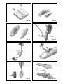
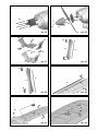
2. Zusammenbau des Fahrwerks (KIT+RR)
Kleben Sie in die innere linke der linken Radverkleidungs-
häfte 18 den linken Radverkleidungshalter 45 ein. Kleben
Sie anschließend die äußere Hälfte der Radverkleidung
19 auf. Mit der rechten Radverkleidung verfahren Sie bitte
analog (Teile 20, 46, 21).
Abb. 20 + 21
Stecken Sie ein Leichtrad 67 in die linke Radverkleidung
und führen Sie dann die Schraube 64 (M4x40) als Radach-
se durch Radverkleidung und Rad. Auf die Schraube drehen
Sie anschließend eine Mutter M4 66 locker auf. Stecken Sie
die Schraube mit einer U-Scheibe 65 nun durch die Bohrung
am linken Bein des Fahrwerksbügels 62 und befestigen Sie
es mit U-Scheiben 65 und Stoppmutter M4 63.
Achtung: „vorne“ beim Fahrwerksbügel ist die gerade Sei-
te! Die Abbildung 47 verdeutlicht das Schema der Montage
noch einmal. Analog dazu wird auch der rechte Radschuh
am Fahrwerksbügel montiert.
Abb. 22
Auf den Fahrwerksbügel kleben Sie mit einem Tropfen
Zacki nun die Fahrwerksabdeckung 22. Prüfen Sie bitte
vor dem Verkleben die Ausrichtung des Teils, indem Sie

Seite 7
es an den Rumpf anhalten. Schrauben Sie das fertig zu-
sammengebaute Fahrwerk nun mit vier Inbus-Schrauben
(M4x12) an den Rumpf.
Abb. 23 + 24
Schieben Sie auf den Spornradbügel das Spornrad 70 auf
und sichern Sie es mit dem Stellring 71.
Abb. 25
3. Leitwerke (KIT+RR)
Kleben Sie in die untere Hälfte des Höhenleitwerks 13 vier
Scharnierachsaufnahmen 44 ein. Zwischen die inneren
Scharnierachsaufnahmen kleben Sie die Hülse für die Hö-
henleitwerksbefestigung 38. Verkleben Sie anschließend
die untere mit der oberen Höhenleitwerkshälfte 12.
Abb. 26
Kleben Sie die Achsen der Hohlkehlenscharniere 43 in
das Höhenruder 14. In den langen Schlitz kleben Sie das
CFK-Rohr 72 (Ø 3mm) ein. Schließen Sie das Höhenruder
durch Einkleben der Höhenruderabdeckung 15 und des
Ruderhorns 49.
Abb. 27
Nun kann das Höhenruder ans Höhenleitwerk angeclipst
werden und in die Aussparung am Rumpf geschoben wer-
den. Gesichert wird es durch eine Kunststoffschraube 48
(M5x60) von unten.
Abb. 28 + 29
Montieren Sie am Ruderhorn einen Gestängeanschluss
53, schieben Sie den F-Stahldraht durch die Bohrung und
sichern Sie ihn bei neutralem Ruder mit einem Gewindestift
M3 55. Abb. 30
Kleben Sie in das Seitenruder 16 ebenfalls zwei Schar-
nierachsen und das Seitenruderhorn 42 ein. Schließen Sie
dann das Seitenruder mit der Seitenruderabdeckung 17.
Das montierte Seitenruder kann nun ebenfalls am Leitwerk
angeclipst werden. Hängen Sie dazu zuerst das Dornlager
am unteren Ende des Leitwerks ein und clipsen sie dann
die Scharniere ein.
Abb. 31 – 33
Auch am Seitenruderhorn montieren Sie wie beim Hö-
henruder einen Gestängeanschluss 53 und klemmen den
F-Stahldraht mit dem Gewindestift M3 55 fest.
Abb. 34
4. Motoreinbau (KIT+RR)
Befestigen Sie den Motor mit vier beiliegenden Schrauben
am Alu-Motorspant 59. Verwenden Sie an allen Schrau-
ben einen Tropfen Schraubensicherungslack (mittelfest)!
Schrauben Sie dann den Motor mit Hilfe der Distanzbolzen
61 und vier Schrauben 60 (M4x65) mit U-Scheiben 65 in
den Rumpf.
Abb. 35
Setzen Sie auf die Motorwelle den Luftschraubenmitnehmer
86 mit Spannkonus 87, die Spinnerplatte 85, den Propeller
84, eine U-Scheibe 83 (Innen Ø 6mm) und Mutter M6 82
auf. Ziehen Sie die Mutter leicht an und drehen Sie den
Propeller gegen die Anschläge auf der Spinnerplatte. Hal-
ten Sie den Propeller in Position während Sie die Mutter
vollständig anziehen.
Setzen Sie abschließend die Spinnerkappe 81 auf und
schrauben Sie sie mit zwei Schrauben 81 (3x16mm) an
der Spinnerplatte fest.
Abb. 36
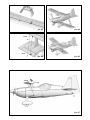
5. Zusammenbau der Trag! ächen (KIT+RR)
Zunächst wird der Baldachin für die obere Tragfläche
montiert. Dazu werden die Baldachinstreben 23 und 24 und
die Hülse für die Flächenbefestigung 35 an das Baldachin-
zwischenstück 25 geklebt. In die Unterseite der Abdeckung
kleben Sie jeweils die linke und rechte Baldachinarretierung
29 und 30, danach noch die CFK-Leiste 78 (3x1x100mm).
Abb. 37
Kleben Sie in die beiden Tragfl ächenstreben 10 und 11
jeweils oben und unten einen Clip für die Streben 36 ein
und auf der Rückseite eine CFK-Leiste 77 (3x1x190mm).
Achten Sie darauf, dass kein Klebstoff in den Clip fl ießt.
Abb. 38 + 39
In die obere Tragfl äche 8 kleben Sie das Holmrohr 79 und
beidseitig eine Aufnahme für die Strebenclips 37. An den
Querrudern befi nden sich Aussparungen für die Aufnah-
men der Querruderverbinder 50. Kleben Sie auch diese
beidseitig ein.
Abb. 40
Stellen Sie die Querruderservos mittels Ihrer Fernsteuerung
in Neutralposition und schrauben Sie die Servohebel auf.
Kleben Sie die Servos in die untere Tragfl äche 9 an ihre
vorgesehene Position. Verwenden Sie hierzu nur etwas
Heißkleber an den Servolaschen. Die Kabel verlegen Sie
in den dafür vorgesehenen Kabelkanälen und kleben Sie
mit etwas Tesafi lm ab. Außerdem kleben Sie in die Querru-
der beidseitig je ein Ruderhorn 49 und eine Aufnahme für
die Querruderverbinder 50 ein. Im angeformten Rumpfteil
kleben Sie in die Bohrung eine Hülse zur Flächenbefesti-
gung 35.
Abb. 41
Hängen Sie in die Querruderservos jeweils ein Querruder-
gestänge 75 ein und verbinden Sie es in gewohnter Art
und Weise mit einem Gestängeanschluss 53 und einem
Gewindestift M3 55 mit dem Ruderhorn.
Abb. 42
Verkleben Sie den zusammengebauten Baldachin sorgfältig
mit der oberen Tragfl äche (Ausrichtung beachten!).
Abb. 43
6. Einbau der Empfangsanlage (KIT+RR)
Stecken Sie alle Servokabel in den Empfänger und pro-
grammieren Sie das Modell gemäß den angegebenen
Ruderausschlägen. Die Steckerordnung bei MULTIPLEX ist
(sofern nicht anderweitig frei zugeordnet) folgendermaßen:
1. Querruder links
2. Höhenruder
3. Seitenruder
4. Gas
5. Querruder rechts

Seite 8
Befestigen Sie den Empfänger mit Klettband auf der Un-
terseite des M-Frames. Für eine feste Verbindung des
Klettbandes am Holz empfehlen wir ein paar Tropfen Zacki
hinzu zu geben. Zusätzlich können Sie den Empfänger mit
einem Kabelbinder sichern.
7. Endmontage des Flugzeugs (KIT+RR)
Stecken Sie zunächst die untere Fläche an den Rumpf.
Drehen Sie dazu den Rumpf auf den Rücken und führen
Sie die Tragfl äche mit der Nasenleiste in die Ecke zwischen
Fahrwerk und Radverkleidung. Nun schleißen Sie die
Querruderkabel am Empfänger an. Klappen Sie dann die
Endleiste zum Rumpf hin und stecken Sie die Lasche in
den Rumpf. Nun kann die Tragfl äche vollständig angelegt
und mit einer Kunststoffschraube 47 (M5x35) verschraubt
werden.
Stellen Sie das Flugzeug wieder aufs Fahrwerk und clipsen
Sie die Tragfl ächenstreben links und rechts an die untere
Tragfl äche. Stecken Sie nun die obere Tragfl äche mit dem
Baldachin auf den Rumpf und clipsen Sie die Tragfl ächen-
streben auch oben fest. Abschließend Verschrauben Sie
auch diese Tragfl äche mit einer Kunststoffschraube 47
(M5x35) mit dem Rumpf.
Abb. 44
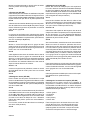
Zur Verbindung der Querruder dienen zwei Gestänge aus
Metall 76. Montieren Sie zunächst an allen Aufnahmen
für die Querruderverbinder Gestängeanschlüsse. Dabei
verwenden Sie auf der linken Seite rote Teile 51 und auf
der rechten Seite grüne Teile 52.
Richten Sie die Querruder neutral aus und befestigen Sie
zunächst oben einen Querruderverbinder mit einem Gewin-
destift M3 55. Wenn oberes und unteres Querruder neutral
stehen, befestigen Sie auch unten den Querruderverbinder
mit einem Gewindestift M3.
Gehen Sie auf der anderen Seite analog vor!
Abb. 45 + 46
Bei der Demontage des Flugzeugs clipsen Sie lediglich
die Gestängeanschlüsse aus ihren Aufnahmen. So bleibt
die gleichmäßige Abstimmung der Querruder zueinander
erhalten. Durch die Farben der Anschlüsse lässt sich sofort
erkennen, auf welche Seite sie gehören:
ROT = links
GRÜN = rechts
8. Auswiegen (KIT+RR)
Kleben Sie zunächst mit Zacki die beiden Trimmgewichte
91 in den Motorraum, sodass sich die Motorhaube noch
schließen lässt.
Schieben Sie den Antriebsakku auf der Akkurutsche so
in Position, dass der Schwerpunkt bei 100 mm liegt
(gemessen von der oberen Trag! ächenvorderkante in
Rumpfnähe). Befestigen Sie den Akku mit den beiliegen-
den Klettbändern 88 und 89 und mit der Klettbandschlaufe
90.
Für eine feste Verbindung des Klettbandes am Rumpfbo-
den empfehlen wir ein paar Tropfen Zacki hinzu zu geben.
9. Empfohlene Ruderausschläge
für klassischen Programmkunstfl ug:
Seitenruder: rechts/links 40 mm 60% EXPO
Höhenruder: hoch 40 mm, runter 40 mm 70%
EXPO
Querruder: hoch 17 mm runter 17 mm 50%
EXPO
Mischer (linear): 3,5mm Querruder auf Seitenruder
entgegengesetzt
àD.h.: bei SR voll rechts, fährt
das QR 3,5mm links
4mm Höhenruder auf Seitenruder
àD.h.: bei SR voll R+L fährt das
HR 4mm nach oben
Für 3D-Kunstfl ug:
Seitenruder: rechts/links: 65 mm 60% EXPO
Höhenruder: hoch / runter: 55mm 70% EXPO
Querruder: hoch 22 mm / runter 22 mm 50%
EXPO
Mischer (linear): 3,5mm Querruder auf Seitenruder
entgegengesetzt
àD.h.: bei SR voll rechts, fährt
das QR 3,5mm links
4mm Höhenruder auf Seitenruder
àD.h.: bei SR voll R+L fährt das
HR 4mm nach oben

Seite 9
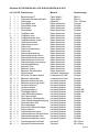
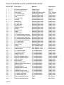
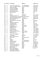
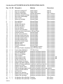
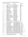
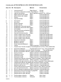
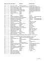
Stückliste KIT ROCKSTAR # 21 4278 & RR ROCKSTAR # 26 4278:
Lfd.
Kit RR Bezeichnung Material Abmessungen
1 1 1 Bauanleitung KIT Papier 80g/m² DIN-A4
2 1 1 Reklamationsmeldung Modelle Papier 80g/m² DIN-A4
3 1 1 Dekorbogen Klebefolie 700 x 1000mm
4 1 1 Rumpfhälfte links Elapor geschäumt Fertigteil
5 1 1 Rumpfhälfte rechts Elapor geschäumt Fertigteil
6 1 1 Motorhaube Elapor geschäumt Fertigteil
7 1 1 Rumpfdeckel Elapor geschäumt Fertigteil
8 1 1 Tragfl äche oben Elapor geschäumt Fertigteil
9 1 1 Tragfl äche unten Elapor geschäumt Fertigteil
10 1 1 Tragfl ächenstrebe links Elapor geschäumt Fertigteil
11 1 1 Tragfl ächenstrebe rechts Elapor geschäumt Fertigteil
12 1 1 Höhenleitwerk oben Elapor geschäumt Fertigteil
13 1 1 Höhenleitwerk unten Elapor geschäumt Fertigteil
14 1 1 Höhenruder Elapor geschäumt Fertigteil
15 1 1 Höhenruderabdeckung Elapor geschäumt Fertigteil
16 1 1 Seitenruder Elapor geschäumt Fertigteil
17 1 1 Seitenruderabdeckung Elapor geschäumt Fertigteil
18 1 1 Radverkleidung links innen Elapor geschäumt Fertigteil
19 1 1 Radverkleidung links aussen Elapor geschäumt Fertigteil
20 1 1 Radverkleidung rechts innen Elapor geschäumt Fertigteil
21 1 1 Radverkleidung rechts aussen Elapor geschäumt Fertigteil
22 1 1 Fahrwerksabdeckung Elapor geschäumt Fertigteil
23 1 1 Baldachin links Elapor geschäumt Fertigteil
24 1 1 Baldachin rechts Elapor geschäumt Fertigteil
25 1 1 Baldachin-Zwischenstück Elapor geschäumt Fertigteil
26 1 1 Kabinenhaube Kunststoff, tiefgezogen Fertigteil
27 1 1 Motordom Tornado komplett Lindensperrholz 3mm Fertigteil
28 4 4 Baldachin-Gegenlager Lindensperrholz 3mm Fertigteil
29 1 1 Baldachin-Arretierung links Kunststoff gespritzt Fertigteil
30 1 1 Baldachin-Arretierung rechts Kunststoff gespritzt Fertigteil
31 2 2 Verschlussklammer Kunststoff gespritzt Fertigteil
32 2 2 Verschlusszapfen Kunststoff gespritzt Fertigteil
33 2 2 Flügelgegenlager A Kunststoff gespritzt Fertigteil M5
34 2 2 Flügelgegenlager B Kunststoff gespritzt Fertigteil M5
35 2 2 Hülse Flächenbefestigung Kunststoff gespritzt Fertigteil
36 4 4 Clip Flächenstrebe Kunststoff gespritzt Fertigteil
37 4 4 Clipaufnahme Flächenstrebe Kunststoff gespritzt Fertigteil
38 1 1 Hülse Höhenleitwerksbefestigung Kunststoff gespritzt Fertigteil
39 1 1 Mutteraufnahme (M5) Kunststoff gespritzt Fertigteil
40 1 1 Spornradaufl ager Kunststoff gespritzt Fertigteil
41 1 1 Klemmstück Spornradaufl ager Kunststoff gespritzt Fertigteil
42 1 1 Seitenruderhorn Kunststoff gespritzt Fertigteil
43 6 6 Hohlkehlscharnier Achse Kunststoff gespritzt Fertigteil
44 6 6 Hohlkehlscharnier Achsaufnahme Kunststoff gespritzt Fertigteil
45 1 1 Radverkleidungshalter links Kunststoff gespritzt Fertigteil
46 1 1 Radverkleidungshalter rechts Kunststoff gespritzt Fertigteil
47 2 2 Zylinderschraube Kunststoff Kunststoff M5 x 35mm
48 1 1 Kunststoff-Zylinderschraube Polyamid M5 x 60mm

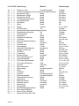
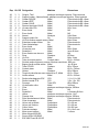
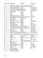
Seite 10
Lfd.
Kit RR Bezeichnung Material Abmessungen
49 3 3 Ruderhorn „Twin“ Kunststoff gespritzt Fertigteil
50 4 4 Aufnahme Kardanbolzen-Querruderverb. Kunststoff gespritzt Fertigteil
51 2 2 Kardanbolzen ROT Metall Ø6 x 8mm
52 2 2 Kardanbolzen GRÜN Metall Ø6 x 8mm
53 4 4 Kardanbolzen KLAR Metall Ø6 x 8mm
54 2 2 Gestängeanschluss KLAR Metall Ø6 x 8mm
55 11 11 Inbus-Gewindestift Metall M3 x 3mm
56 2 2 Stop-Mutter Metall M2
57 1 1 Mutter Metall M5
58 8 8 Magnet Neodym 5 x 2 x 10mm
59 1 1 Alu-Motorspant Alu Fertigteil
60 4 4 Inbusschraube Motorspantbefestigung, Metall M4 x 65mm
61 4 4 Distanzbolzen Motorspant Alu Fertigteil
62 1 1 Fahrwerksbügel Alu Fertigteil
63 2 2 Stoppmutter Metall M4
64 2 2 Schraube für Radachse Metall M4 x 40mm
65 8 8 U-Scheibe Metall innen Ø 4mm
66 2 2 Muttern Radachsbefestigung Metall M4
67 2 2 Leichtrad Kunststoff Ø73mm
68 4 4 Inbusschraube Metall M4 x 12mm
69 1 1 Spornradbügel F-Stahl Ø1,5 x 210mm
70 1 1 Leichtrad für Heckfahrwerk Moosgummi Ø26 mm
71 1 1 Stellring für Spornrad Metall innen Ø 2mm
72 1 1 CFK-Rohr Metall Ø3 x 370mm
73 2 2 F-Stahldraht Metall Ø1,2 x 740mm
74 2 2 Bowdenzugrohre Kunststoff Ø3 x 590mm
75 2 2 Querrudergestänge m.Z Metall Ø1,3 x 70mm
76 2 2 Querruderverbinder Metall Ø1,5 x 210mm
77 2 2 CFK-Leiste Flächenstrebe CFK 3 ,0 x 1,0 x 190
78 1 1 CFK-Leiste Mittelstrebe CFK 3,0 x 1,0 x 100
79 1 1 Holmrohr GFK-Rohr Ø8 x 800mm
80 2 2 Spinnerschrauben Metall 3 x 16mm
81 1 1 Spinnerkappe Kunststoff gespritzt Ø62mm
82 1 1 Mutter Metall M6
83 1 1 U-Scheibe Metall innen Ø 6mm
84 1 1 Propeller Kunststoff gespritzt 14 x 7“
85 1 1 Spinnergrundplatte Kunststoff gespritzt Ø62mm
86 1 1 Luftschraubenmitnehmer Metall Fertigteil
87 1 1 Spannkonus Metall Fertigteil
88 3 3 Klettband Pilzkopf Kunststoff 25 x 60mm
89 3 3 Klettband Velours Kunststoff 25 x 60mm
90 1 1 Klettschlaufe Kunststoff 25 x 200mm
91 2 2 Trimmgewicht Metall 25 x 19 x 5mm
92 0 4 Motorbefestigungsschrauben Metall 3 x 8mm
93 0 1 Motor Himax 4220-620
94 0 4 Servos HiTec HS-82MG
95 0 1 Regler MULTIcont BL-60 SD

Seite 11
Safety Information for MULTIPLEX model aircraft
This model is NOT A TOY in the usual sense of the term.
By operating the model the owner affi rms that he is aware of the content of the operating instructions, especially those
sections which concern safety, maintenance, operating restrictions and faults, and is capable of fulfi lling these requirements.
This model must not be operated by any child under fourteen years of age. If a person below this age operates the model
under the supervision of a competent adult who is acting as the child’s guardian within the legal sense of the term, this
individual is responsible for the implementation of the information in the OPERATING INSTRUCTIONS.
THE MODEL AND ASSOCIATED ACCESSORIES MUST BE KEPT OUT OF THE REACH OF CHILDREN UNDER THREE
YEARS OF AGE! MODELS CONTAIN SMALL DETACHABLE PARTS WHICH MAY BE SWALLOWED BY CHILDREN
UNDER THREE YEARS. CHOKING HAZARD!
All the warnings in the OPERATING INSTRUCTIONS must be observed whenever the model is operated. Multiplex
Modellsport GmbH & Co. KG accepts no liability for loss or damage or any kind which occurs as a result of incorrect
operation or misuse of this product, including the accessories required for its operation. This includes direct, indirect,
deliberate and accidental loss and damage, and all forms of consequent damage.
Every safety note in these instructions must always be observed, as all the information contributes to the safe opera-
tion of your model. Use your model thoughtfully and cautiously, and it will give you and your spectators many hours of
pleasure without constituting a hazard. Failure to operate your model in a responsible manner may result in signifi cant
property damage and severe personal injury. You alone bear the responsibility for the implementation of the operating
instructions and the safety notes.
Approved usage
The model is approved exclusively for use within the modelling hobby. It is prohibited to use the model for any other
purpose than that stated. The operator of the model, and not the manufacturer, is responsible for damage or injury of
any kind resulting from non-approved use.
The model may only be operated in conjunction with those accessories which we expressly recommend. The recom-
mended components have undergone thorough testing, are an accurate match to the model, and ensure that it functions
safely. If you use other components, or modify the model, you operate it at your own risk, and any claim under guarantee
is invalidated.
To minimise the risk when operating the model, please observe the following points:
l The model is guided using a radio control system. No radio control system is immune to radio interference, and
such interference may result in loss of control of the model for a period of time. To avoid collisions, you must
therefore ensure at all times that there is a wide margin of safety in all directions when operating your model. At
the slightest sign of radio interference you must cease operating your model!
l Never operate your model until you have successfully completed a thorough check of the working systems, and
carried out a range-check as stipulated in the instructions supplied with your transmitter.
l The model may only be fl own in conditions of good visibility. You can avoid being temporarily blinded by not fl ying
towards the sun, or in other diffi cult light conditions.
l A model must never be operated by a person who is under the infl uence of alcohol, drugs or medication which
have an adverse effect on visual acuity and reaction time.
l Only fl y your model in conditions of wind and weather in which you are able to maintain full control of the model.
Even when the wind is light, bear in mind that turbulence can form at and around objects which may have an
effect on the model.
l Never fl y in any location where you may endanger yourself of others, e.g. close to residential areas, overhead
cables, open roads and railway lines.
l Never fl y towards people or animals. You may think that fl ying low over other people’s heads is proof of your
piloting skill, but all it does is place others at unnecessary risk. It is in all our interests that you let other pilots
know that this is what you think. Always fl y in such a way that you do not endanger yourself or others. Bear in
mind that even the best RC system in the world is subject to outside interference. No matter how many years of
accident-free fl ying you have under your belt, you have no idea what will happen in the next minute.
GB

Seite 12
Residual risks
Even if the model is operated in the correct manner, and you observe all safety aspects, there is always a certain residual
risk.
For this reason it is mandatory to take out third-party liability insurance. If you join a club or fl ying association, insurance
is usually available or included in the annual fee. Make sure that your insurance cover is adequate (i.e. that it covers
powered model aircraft). Always keep your models and your radio control equipment in perfect order.
The following hazards may occur owing to the model’s construction and type:
l Injury caused by the propeller: you must keep well clear of the area around the propeller from the moment that
the battery is connected. Please bear in mind that objects in front of the propeller may be sucked into it, and
objects behind the propeller may be blown away by it. The model may start moving when the propeller starts
to turn. You must therefore position the model in such a way that it cannot move towards other persons if the
motor should unexpectedly start running. When you are carrying out adjustment work involving the running
motor, you must ensure that the model is always held securely by an assistant.
l Crash caused by pilot error: this can happen even to the best of pilots, so it is essential to fl y exclusively in a
safe environment: an approved model fl ying site and suitable insurance are basic essentials.
l Crash caused by technical failure or unnoticed damage in transit or in the workshop. A thorough check of the
model before every fl ight is essential. However, you should also take into account at all times that material
failures can and do occur. Never fl y in a location where your model may damage or injure others.
l Keep within the stated operating limits. Excessively violent fl ying will weaken the airframe, and may result in
sudden material failure, or may cause the model to crash during a subsequent fl ight due to “creeping” conse-
quent damage.
l Fire hazard caused by electronic failure or malfunction. Store batteries safely, and always observe safety
notes which apply to the airborne electronic components, the battery and the battery charger. Protect all elec-
tronic equipment from damp. Ensure that the speed controller and battery are adequately cooled.
The instructions which accompany our products must not be reproduced and / or published, in full or in part, in
print or any electronic medium, without the express written approval of Multiplex Modellsport GmbH & Co. KG.
GB

Seite 13
Examine your kit carefully!
MULTIPLEX model kits are subject to constant quality checks throughout the production process, and we sincerely
hope that you are completely satisfi ed with the contents of your kit. However, we would ask you to check all the parts
before you start construction, as we cannot exchange components which you have already worked on. If you fi nd
any part is not acceptable for any reason, we will readily correct or exchange it. Just send the component to our Model
Department. Please be sure to include the purchase receipt and a brief description of the fault.
We are constantly working on improving our models, and for this reason we must reserve the right to change the kit
contents in terms of shape or dimensions of parts, technology, materials and fi ttings, without prior notifi cation. Please
understand that we cannot entertain claims against us if the kit contents do not agree in every respect with the instruc-
tions and the illustrations.
Caution!
Radio-controlled models, and especially model aircraft, are by no means playthings. Building and operating them
safely requires a certain level of technical competence and manual skill, together with discipline and a respon-
sible attitude at the " ying # eld. Errors and carelessness in building and " ying the model can result in serious
personal injury and damage to property. Since we, as manufacturers, have no control over the construction,
maintenance and operation of our products, we are obliged to take this opportunity to point out these hazards
and to emphasise your personal responsibility.
Warning:
Like every aeroplane, this model has static limits. Steep dives and senseless manoeuvres inappropriate to the type
may result in the loss of the aircraft. Please note: we will not replace the model in such cases. It is your responsibility to
approach the airframe’s limits gradually. It is designed for the power system recommended in these instructions, but is
only capable of withstanding the fl ight loads if built exactly as described and if it is in an undamaged state.
Recommended equipment:
Zacki ELAPOR 20g VE1 RR+KIT Item number: 852727
Li-BATT FX 4/1 2600 (M6) RR+KIT Item number: 157362
Receiver RX-5 light M-LINK 2,4 GHz RR+KIT Item number: 55808
Drive set ROCKSTAR KIT Item number: 332667
Servo HS-82 MG (4x) KIT Item number: 112088
Extension lead 15 cm (UNI) (2x) KIT Item number: 85019
GB

Seite 14
Important note
This model is not made of Styrofoam™, and it is not possible to glue the material using white glue, polyurethane or
epoxy; these adhesives only produce superfi cial joints, and simply break away under stress. Please be sure to use
medium-viscosity cyano-acrylate glue exclusively, preferably Zacki ELAPOR® # 59 2727, which is optimised specifi cally
for ELAPOR® particle foam. If you se Zacki ELAPOR® there is usually no need for cyano ‘kicker’ or activator. However,
if you wish to use a different adhesive which requires the use of activator, please note that these materials are injurious
to health, and should always be applied in the open air. Take care when handling all cyano-acrylate adhesives, as they
harden in seconds, so don’t get them on your fi ngers or other parts of the body. We strongly recommend the use of
goggles to protect your eyes. Keep the adhesive out of the reach of children! For certain joints it is also possible to use
hot-melt adhesive; the instructions indicate where this is the case.
Working with Zacki ELAPOR®
Zacki ELAPOR® has been developed specifi cally for glued joints in our models which consist of moulded ELAPOR®
foam parts.
Please observe the following points in order to obtain perfect joints:
• Avoid the use of activator. ‘Kicker’ signifi cantly weakens the joint. We advise leaving joined parts for 24 hours to obtain
maximum strength, particularly when the glued area is large.
• Activator should only be used for temporary, small-area joints (‘tacking’). Spray a little activator on one surface, and
allow it to air-dry for about thirty seconds.
• To obtain maximum joint strength you should lightly sand the surface with 320-grit abrasive paper before applying glue.
Bent parts - actually don’t exist. If you ! nd that a component has taken up a curve, perhaps after being trans-
ported, it is easy to straighten again. In this respect ELAPOR® behaves in a similar way to metal: bend the
component back slightly beyond the correct position, and the material will then spring back to its proper shape
when released, and maintain it. There are limits, however - don’t overdo it"
Bent parts - really do exist. If you wish to paint your model, apply MPX Primer # 60 2700 to the surfaces, wiping it on
very lightly as if you were cleaning the model. Paint must always be applied thinly and evenly, otherwise the component
will warp. Then you really will have bent parts, and they will also be heavy and perhaps even unusable. We have found
that matt-fi nish paints produce the best visual effect.
Technical information ROCKSTAR:
Wingspan: 1050 mm
Overall length: 1060 mm
All-up weight: 1800 g
Total surface area: 48 dm²
Wing loading: 38 g/dm²
Channels: 5
RC Functions: rudder, elevator, aileron, motor
Flight time: ca. 7 min (4S ~2600 mAh)
Note: please remove the pictures from the center of the instructions"

Seite 15
Congratulations on your new ROCKSTAR!
You will need the following tools to build the model:
2 x Zacki-Elapor # 85 2727 (KIT) (1xRR)
1 x UHU Por (KIT)
Hot glue gun (KIT)
Medium-sized cross-point screwdriver (KIT)
Medium-sized slot-head screwdriver (KIT)
Balsa knife (KIT)
Pointed-nose pliers (KIT)
1.5 mm A/F allen key (KIT)
3 mm A/F allen key (KIT)
10 mm A/F open-ended spanner (KIT)
2.5 mm drill (KIT)
Before starting construction:
Please check that all the parts are present, referring to the
Parts List on page 18+19 (Figs. 01 & 02).
1. Assembling the fuselage (KIT)
Clip together the two parts 33 and 34 which form the spread-
er plate for the wing retaining bolt, and glue the joint with
Zacki. ! Caution ! Watch out for excess glue squirting out
when the parts are joined. Glue the Canopy Lock clip 31,
the cabane socket 28 and the wing bolt spreader plate in
the right-hand fuselage shell 5. Glue the two rudder hinge
pin supports 44 in the slots in the right-hand fi n shell. At the
same time glue the M5 nut support 39 and the tailwheel
bracket 40 in place.
Figs. 03 + 04
Slip a length of spring steel wire 73 through the snake out-
er sleeve 74, and lay it in the right-hand fuselage shell as
shown; the snake outer should project about 30 mm from
the tail end of the fuselage. Glue it in place permanently.
Figs. 05 – 07
Now glue the pre-assembled M-Frame 27 in the right-hand
fuselage shell 5.
Fig. 08
Working in a similar manner, glue the following parts in the
left-hand fuselage shell 4: the Canopy Lock clip 31 and the
cabane socket 28. A second spring steel rod 73 should now
be slipped into a snake outer sleeve 74, and fi tted in the
left-hand fuselage shell; this should also project at the tail
end by about 30 mm.
Figs. 09 – 11
Now offer up the two fuselage shells to each other dry
(WITHOUT glue), and check that they fi t together snugly at
all points. When you are confi dent that everything matches
up correctly, apply glue to the joint surfaces, fi t the two shells
together, and check that they are accurately aligned.
Figs. 12 + 13
With this step complete, it is time to paint the dummy pilot
in the colour scheme of your choice.
Please note that dark areas under the canopy may heat
up strongly if subjected to direct sunshine. If this should
happen, the ELAPOR foam may swell and bubble!
Apply the instrument panel sticker (decal sheet) to the
moulded-in binnacle inside the cockpit. When you are sat-
isfi ed with the appearance of your cockpit, glue the canopy
26 to the fuselage using UHU Por.
Fig. 14
Locate the four magnets 58 which retain the cowl 6, and glue
them in the appropriate recesses at the front of the fuselage.
Fig. 15
Hold the rudder servo in your hand and centre it from the
transmitter. Drill out the outermost hole in the servo output
arm using a 2.5 mm Ø bit. Fit the output arm on the servo
shaft as shown in Fig. 16, and secure it with the output
screw. Mount the swivel pushrod connector 54 in the outer
hole in the output arm, securing it with the M2 self-locking nut
56. Fit an M3 grubscrew 55 in the open end of the pushrod
connector barrel.
Place the servo in the opening in the left-hand side of the
M-Frame, and secure it with the retaining screws supplied
with the servo.
Fig. 16
Repeat the procedure with the elevator servo, with this ex-
ception: fi t the output arm on the servo facing the opposite
direction. Install the elevator servo in the right-hand opening
in the M-Frame.
Fig. 17
Glue the four remaining magnets 58 in the appropriate
recesses in the cowl 6.
! CAUTION !: Ensure that the pairs of magnets attract,
rather than repel!
Fig. 18
Glue the two Canopy Lock lugs 32 in the slots in the fuse-
lage hatch 7.
Fig. 19
2. Assembling the undercarriage (KIT+RR)
Glue the left-hand wheel spat holder 45 in the inboard left-
hand wheel spat shell 18, then glue the outboard wheel spat
shell 19 to the inboard shell. Repeat the procedure with the
right-hand wheel spat (parts 20, 46 and 21).
Figs. 20 + 21
Place one lightweight wheel 67 in the left-hand wheel spat,
then slip the wheel axle (M4 x 40 mm machine screw) 64
through the spat and wheel. Fit an M4 nut 66 loosely on the
end of the screw. Fit a washer 65 on the screw, then slip it
through the hole in the left-hand leg of the undercarriage
unit 62 before securing it with a further washer 65 and an
M4 self-locking nut 63.
Caution: the straight edge of the undercarriage unit is
“forward”! Fig. 47 clearly shows the correct orientation of
the undercarriage. Repeat the procedure with the right-
hand wheel spat, and attach it to the right-hand leg of the
undercarriage unit in the same way.
Fig. 22
The next step is to glue the undercarriage fairing 22 to the
metal undercarriage unit with a drop of Zacki, but fi rst check
the correct position of the fairing by holding the undercar-
riage on the fuselage. The completed undercarriage unit
can now be fi xed to the fuselage using four M4 x 12 mm
socket-head screws. Figs. 23 + 24

Seite 16
Fit the tailwheel 70 on the axle of the tailwheel unit, and
secure it with the collet 71.
Fig. 25
3. Tail panels (KIT+RR)
Glue four hinge pin supports 44 in the bottom half of the
tailplane 13. Glue the sleeve 38 for the tailplane retainer
screw between the inboard hinge pin supports as shown,
then glue the bottom tailplane shell 13 to the top tailplane
shell 12.
Fig. 26
Glue the recessed hinge pin units 43 in the elevator 14. Glue
the 3 mm Ø carbon fi bre tube 72 in the long slot. Close the
elevator by gluing the cover 15 in place, followed by the
elevator horn 49.
Fig. 27
The hinges can now be clipped together to attach the ele-
vator to the tailplane. Slide the tailplane assembly into the
slot in the fuselage, and secure it by fi tting the plastic M5 x
60 retaining screw 48 from the underside.
Figs. 28 + 29
Attach a swivel pushrod connector 53 to the elevator horn
and slip the spring steel pushrod through the hole in the
barrel. Set the elevator to neutral (centre), then tighten the
M3 grubscrew 55 in the barrel to clamp the pushrod in place.
Fig. 30
Glue two hinge pin units 43 and the rudder horn 42 in the
rudder 16, then close the rudder by gluing the cover 17 in
place. The completed rudder can now also be attached to
the fi n: fi rst engage the spigot which forms the bottom fi n
hinge, then clip the two upper hinges together.
Figs. 31 – 33
Mount a swivel pushrod connector 53 on the rudder horn
as described for the elevator, and clamp the spring steel
pushrod in the barrel using an M3 grubscrew 55.
Fig. 34
4. Installing the motor (KIT+RR)
Attach the motor to the aluminium mount 59 using the four
screws supplied, not forgetting to apply a drop of medi-
um-strength thread-lock fl uid to each screw! Now install the
motor in the fuselage using the stand-off pillars 61 and four
M4 x 65 mm machine screws 60 and washers 65.
Fig. 35
Fit the propeller driver 86 on the motor shaft together with
the taper collet 87, the spinner backplate 85, the propeller
84, a 6 mm I.D. washer 83 and the M6 nut 82. Tighten the
retaining nut lightly, then rotate the propeller until it rests
against the spinner backplate’s integral bosses. Hold the
propeller in this position while you tighten the retaining nut
fully.
Fit the spinner cap 81 over this assembly, and fi x it to the
spinner backplate using two 3 x 16 mm screws 81.
Fig. 36
5. Completing the wings (KIT+RR)
The fi rst step is to assemble the cabane for the top wing:
glue the cabane struts 23 and 24 and the wing bolt sleeve
35 to the cabane core 25. Glue the left and right cabane
retainers 29 and 30 in the underside of the cover, followed
by the 3 x 1 x 100 mm CFRP strip 78.
Fig. 37
Glue the strut clips 36 to both ends of the two wing struts
10 and 11, and glue a 3 x 1 x 190 mm CFRP strip 77 on
the inboard face of each strut. Take care that no glue runs
into the strut clips.
Figs. 38 + 39
Glue the tubular spar 79 in the channel in the underside of
the top wing 8, and a socket 37 for the strut clips on each
side. You will fi nd recesses in the ailerons for the aileron link
rod supports 50; glue these in place on both sides.
Fig. 40
Centre the aileron servos from your transmitter before
screwing the output arms to the output shafts. The servos
should be glued in the openings in the bottom wing 9,
applying just a little hot-melt glue to the servo mounting
lugs. Deploy the servo leads in the cable ducts, and apply
adhesive tape over the open slots to seal them. Glue a
horn 49 and an aileron link rod support 50 in each aileron.
Locate the hole in the central wing fairing for the wing bolt,
and glue the sleeve 35 in it.
Fig. 41
Connect the pre-formed end of the aileron pushrods 75 to
the aileron servos, and connect them to the aileron horns
in the usual manner, using the swivel pushrod connectors
53 and M3 grubscrews 55.
Fig. 42
Carefully glue the cabane assembly to the underside of the
top wing as shown, ensuring that it fi ts the correct way round!
Fig. 43
6. Installing the receiving system (KIT+RR)
Connect all the servo leads to the receiver, and program the
model memory to give the recommended control surface
travels. Unless you have changed the channel assignment
at the transmitter, the standard sequence for MULTIPLEX
radio systems is as follows:
1. L.H. aileron
2. Elevator
3. Rudder
4. Throttle
5. R.H. aileron
Fix the receiver to the bottom of the M-Frame using hook-
and-loop tape. A few drops of Zacki will ensure that the
tape adheres fi rmly to the wood. The receiver can also be
secured with a cable-tie.

Seite 17
7. Final airframe assembly (KIT+RR)
The fi rst step is to attach the bottom wing to the fuselage:
turn the fuselage onto its back, then guide the leading edge
of the wing into the corner between the undercarriage and
the undercarriage fairing. Connect the aileron lead to the
receiver, then fold the wing’s trailing edge down onto the
wing saddle, and engage the locating lug in the fuselage.
The wing can now be fi nally positioned, and fi xed to the
fuselage using a single M5 x 35 mm plastic screw 47.
Turn the aircraft right side up so that it stands on its un-
dercarriage, and clip the wing struts to the bottom wing on
each side. The top wing and cabane can now be fi tted on
the fuselage, and the top end of the wing struts clipped in
place. The fi nal step is to secure the top wing with a second
M5 x 35 mm plastic screw 47.
Fig. 44
Two metal rods 76 are used to link the top and bottom aile-
rons: fi rst attach swivel pushrod connectors to all four aileron
link rod supports. Note that the red parts 51 belong on the
left-hand side, and the green parts 52 on the right-hand side.
Centre the ailerons from the transmitter before attaching
one aileron link rod at the top using an M3 grubscrew 55.
Clamp the link rod at the bottom with a further M3 grubscrew,
taking care to keep both ailerons centred.
Repeat the procedure on the other side.
Figs. 45 + 46
When dismantling the model, simply unclip the swivel
pushrod connector barrels from their supports; this method
maintains the correct alignment of the ailerons relative to
each other. The colour of the connectors makes it easy to
see the side to which they belong:
RED = left
GREEN = right
8. Balancing (KIT+RR)
First glue the two ballast weights 91 in the motor compart-
ment with Zacki; check that the cowl can still be closed.
Slide the fl ight battery into the battery tray, and adjust its
position until the model balances at the recommended Cen-
tre of Gravity (100 mm back from the top wing leading
edge, measured adjacent to the fuselage). Fix the battery
in place using the strips of hook-and-loop tape 88 and 89
and the hook-and-loop strap 90.
To ensure a strong joint, we recommend applying a few
drops of Zacki to the hook-and-loop tape where it makes
contact with the bottom of the fuselage.
9. Recommended control surface travels
for the classic aerobatic schedule:
Rudder: 40 mm right / left, 60% EXPO
Elevator: 40 mm up, 40 mm down, 70%
EXPO
Ailerons: 17 mm up, 17 mm down, 40%
EXPO
Mixer (linear): 3,5mm aileron to rudder, opposite
travel
ài.e.: ailerons defl ect left by
3,5mm at full right-rudder
For 3D aerobatics:
Rudder: 65 mm right / left, 60% EXPO
Elevator: 55 mm up / 55 mm down, 70%
EXPO
Ailerons: 22 mm up / 22 mm down, 50%
EXPO
Mixer (linear): 3,5mm aileron to rudder, opposite
travel
ài.e.: ailerons defl ect left by
3,5mm at full right-rudder
4mm elevator to rudder
ài.e.: elevator defl ects up by
4mm at full right /left -rudder

Seite 18
Partlist KIT ROCKSTAR # 21 4278 and RR ROCKSTAR # 26 4278:
No. Kit RR Description Material Dimensions
1 1 1 KIT building instructions Paper 80 g/m² DIN-A4
2 1 1 Model complaints form Paper 80 g/m² DIN-A4
3 1 1 Decal sheet Printed self-adhesive fi lm 700 x 1000mm
4 1 1 L.H. fuselage shell Moulded Elapor foam Ready made
5 1 1 R.H. fuselage shell Moulded Elapor foam Ready made
6 1 1 Cowl Moulded Elapor foam Ready made
7 1 1 Fuselage hatch Moulded Elapor foam Ready made
8 1 1 Top wing Moulded Elapor foam Ready made
9 1 1 Bottom wing Moulded Elapor foam Ready made
10 1 1 L.H. wing strut Moulded Elapor foam Ready made
11 1 1 R.H. wing strut Moulded Elapor foam Ready made
12 1 1 Tailplane, top Moulded Elapor foam Ready made
13 1 1 Tailplane, bottom Moulded Elapor foam Ready made
14 1 1 Elevator Moulded Elapor foam Ready made
15 1 1 Elevator cover Moulded Elapor foam Ready made
16 1 1 Rudder Moulded Elapor foam Ready made
17 1 1 Rudder cover Moulded Elapor foam Ready made
18 1 1 L.H. inboard wheel spat shell Moulded Elapor foam Ready made
19 1 1 L.H. outboard wheel spat shell Moulded Elapor foam Ready made
20 1 1 R.H. inboard wheel spat shell Moulded Elapor foam Ready made
21 1 1 R.H. outboard wheel spat shell Moulded Elapor foam Ready made
22 1 1 Central undercarriage fairing Moulded Elapor foam Ready made
23 1 1 L.H. cabane strut Moulded Elapor foam Ready made
24 1 1 R.H. cabane strut Moulded Elapor foam Ready made
25 1 1 Cabane core Moulded Elapor foam Ready made
26 1 1 Canopy Vac.-moulded plastic Ready made
27 1 1 Tornado motor dome, complete Lime plywood, 3 mm Ready made
28 4 4 Cabane socket Lime plywood, 3 mm Ready made
29 1 1 L.H. cabane retainer Inj.-moulded plastic Ready made
30 1 1 R.H. cabane retainer Inj.-moulded plastic Ready made
31 2 2 Canopy Lock clip Inj.-moulded plastic Ready made
32 2 2 Canopy Lock lug Inj.-moulded plastic Ready made
33 2 2 Wing bolt spreader plate A Inj.-moulded plastic Ready made,M5
34 2 2 Wing bolt spreader plate B Inj.-moulded plastic Ready made,M5
35 2 2 Wing bolt sleeve Inj.-moulded plastic Ready made
36 4 4 Wing strut clip Inj.-moulded plastic Ready made
37 4 4 Wing strut clip socket Inj.-moulded plastic Ready made
38 1 1 Tailplane retainer screw sleeve Inj.-moulded plastic Ready made
39 1 1 M5 nut support Inj.-moulded plastic Ready made
40 1 1 Tailwheel bracket Inj.-moulded plastic Ready made
41 1 1 Tailwheel bracket clamp Inj.-moulded plastic Ready made
42 1 1 Rudder horn Inj.-moulded plastic Ready made
43 6 6 Recessed hinge pin unit Inj.-moulded plastic Ready made
44 6 6 Recessed hinge pin support Inj.-moulded plastic Ready made
45 1 1 L.H. wheel spat holder Inj.-moulded plastic Ready made
46 1 1 R.H. wheel spat holder Inj.-moulded plastic Ready made
47 2 2 Plastic cheesehead screw Plastic M5 x 35mm
48 1 1 Plastic cheesehead screw Nylon M5 x 60mm

Seite 19
No. Kit RR Description Material Dimensions
49
3 3 „Twin“ control surface horn Inj.-moulded plastic Ready made
50 4 4 Aileron link rod barrel support Inj.-moulded plastic Ready made
51 2 2 Swivel barrel RED Metal 6 Ø x 8mm
52 2 2 Swivel barrel GREEN Metal 6 Ø x 8mm
53 4 4 Swivel barrel CLEAR Metal 6 Ø x 8mm
54 2 2 Swivel barrel CLEAR Metal 6 Ø x 8mm
55 11 11 Socket-head grubscrew Metal M3 x 3mm
56 2 2 Self-locking nut Metal M2
57 1 1 Nut Metal M5
58 8 8 Magnet Neodymium 5 x 2 x 10mm
59 1 1 Aluminium motor mount Aluminium Ready made
60 4 4 Socket-head screw, motor bulkhead mounting, Metal M4 x 65mm
61 4 4 Motor bulkhead stand-off pillar Aluminium Ready made
62 1 1 Main undercarriage unit Aluminium F38 Ready made
63 2 2 Self-locking nut Metal M4
64 2 2 Machine screw for wheel axle Metal M4 x 40mm
65 8 8 Washer Metal 4mm I.D.
66 2 2 Wheel axle retaining nut Metal M4
67 2 2 Lightweight wheel Plastic 73mm Ø
68 4 4 Socket-head screw Metal M4 x 12mm
69 1 1 Tailwheel unit Spring steel 1.5Ø x 210mm
70 1 1 Lightweight tailwheel Foam rubber 26mm Ø
71 1 1 Tailwheel collet Metal 2mm I.D.
72 1 1 CFRP tube, 3 Ø Metal 3 Ø x 370mm
73 2 2 Spring steel wire Metal 1.2Ø x 740mm
74 2 2 Snake outer sleeve Plastic 3 Ø x 590mm
75 2 2 Pre-formed aileron pushrod Metal (1.4310) 1.3 Ø x 70mm
76 2 2 Aileron link rod Metal (1.4310) 1.5Ø x 210mm
77 2 2 CFRP strip, wing strut CFRP 3x1 x 190mm
78 1 1 CFRP strip, central strut CFRP 3x1 x 100mm
79 1 1 Tubular spar GRP tube 8 Ø x 800mm
80 2 2 Spinner retaining screw Metal 3 x 16mm
81 1 1 Spinner cap Inj.-moulded plastic 62mm Ø
82 1 1 Nut Metal M6
83 1 1 Washer Metal 6mm I.D.
84 1 1 Propeller Inj.-moulded plastic 14 x 7“
85 1 1 Spinner backplate Inj.-moulded plastic 62mm Ø
86 1 1 Propeller driver Metal Ready made
87 1 1 Taper collet Metal Ready made
88 3 3 Hook-and-loop tape, hook Plastic 25 x 60mm
89 3 3 Hook-and-loop tape, loop Plastic 25 x 60mm
90 1 1 Hook-and-loop strap Plastic 25 x 200mm
91 2 2 Ballast weight Metal 25 x 19x5mm
92 0 4 Motor mount screws Metal 3 x 8mm
93 0 1 Motor Himax 4220-620
94 0 4 Servos HiTec HS-82MG
95 0 1 ESC MULTIcont BL-60 SD

Seite 20
Consignes de sécurités pour les modèles volants MULTIPLEX
Le modèle n’est PAS UN JOUET.
En utilisant ce modèle, le propriétaire de celui-ci déclare avoir pris connaissance du contenu de la notice d’utilisation,
particulièrement concernant les consignes de sécurités, l’entretien ainsi que les restrictions et défauts d’utilisations, et
qu’il a bien compris le sens de ces consignes
Ce modèle ne doit pas être utilisé par des enfants de moins de 14 ans. Si des personnes mineures devaient utiliser ce
modèle sous la surveillance d’une personne responsable, au sens légal du terme, et expérimentée, celui-ci porte donc
la responsabilité concernant le respect des consignes contenu dans la NOTICE D’UTISATION!
LE MODÈLE AINSI QUE TOUT L’ÉQUIPEMENT NÉCESSAIRE DOIT ÊTRE ÉLOIGNÉ DES ENFANTS DE MOINS DE
3 ANS! LES PARTIES AMOVIBLES DU MODÈLE PEUVENT ÊTRES AVALÉES PAR LES ENFANTS DE MOINS DE 3
ANS. DANGER D’ÉTOUFFEMENT!
Lors de l’utilisation de votre modèle il est impératif de respecter toutes les indications relatives aux dangers décrits dans
la NOTICE D’UTISATION. La société Multiplex Modellsport GmbH & Co. KG ne peut pas être tenue pour responsable
concernant la perte ou tout type d’endommagement de votre modèle résultant à un abus ou une mauvaise utilisation de
ce produit, ainsi que des accessoires. Cela comprend également la perte ou les dommages directs ou indirects, ainsi
que de toute forme de dommages résultants
Chaque consigne de sécurité contenue dans la notice doit obligatoirement être respectée et contribue directement à une
utilisation sécurisée de votre modèle. Utilisez votre modèle intelligemment et avec prudence, cela procurera beaucoup
de plaisir à vous et à vos spectateurs sans pour autant les mettre en danger. Si vous n’utilisez pas correctement votre
modèle, ceux-ci peut conduire à des dommages sur lui-même ou des blessures plus ou moins graves sur vous ou autrui.
Vous seul êtes responsables de la transposition correcte des indications contenues dans la notice
Utilisation conforme
Ce modèle doit exclusivement être utilisé dans le domaine du modèle réduit. Toute utilisation dans un autre domaine
est absolument interdite. Pour tout dommage ou blessure sur des personnes ou des animaux résultant d’une utilisation
non conforme, c’est l’utilisateur qui en porte la responsabilité et non le fabricant.
N’utilisez votre modèle qu’avec les accessoires conseillés. Les composants/accessoires conseillés sont testés sur leur
fonctionnalité et compatibilité par rapport au modèle. Si vous deviez en utiliser d’autres ou modifi er le modèle, vous
utiliserez celui-ci à vos risques et périls, sans oublier que les différentes garanties constructeur / revendeur ne sont plus
valables.
Afi n de minimiser les risques lors de l’utilisation de votre modèle, il est important de respecter les points suivants:
l Le modèle est piloté au travers d’un émetteur. Malheureusement aucun émetteur n’est à l’abri de problèmes
d’émissions. Ce genre de perturbations peut entraîner une perte momentanée du contrôle de votre modèle.
De ce fait, et afi n de minimiser au maximum les collisions potentielles, il est vital d’utiliser votre modèle d’une
manière la plus sécurisé possible à tout point de vue. Dès que vous semblez détecter la moindre anomalie de
fonctionnement il faut absolument arrêter de l’utiliser!
l Vous ne devez réutiliser votre modèle qu’après avoir effectué un test complet de toutes les fonctions ainsi qu’un
test de portée, en fonction des indications de la notice de votre émetteur.
l Le modèle ne doit être utilisé que par temps clair et avec une bonne visibilité. Ne volez pas dans le soleil afi n
de ne pas être ébloui, ou, si la lumière environnante devait être trop faible pour assurer la bonne visibilité de
votre modèle.
l Le modèle ne doit pas être utilisé si vous êtes sous l’infl uence d’alcool, autres drogues ou médicaments pouvant
alterner votre perception et vos réfl exes, entraînant ainsi une diminution de votre vitesse de réaction.
l Ne volez que par un temps sans vent et par lequel vous ne rencontrez pas de problème pour garder en per-
manence votre modèle sous contrôle. Pensez toujours que, même par faible vent, il peut y avoir des tourbillons
induits par le relief pouvant avoir des infl uences sur votre modèle.
l Ne volez jamais à des endroits où vous pourriez mettre en danger autrui ou vous-même, par exemple près des
habitations, lignes à haute tension, routes ou vois ferrée.
F
Seite laden ...
Seite laden ...
Seite laden ...
Seite laden ...
Seite laden ...
Seite laden ...
Seite laden ...
Seite laden ...
Seite laden ...
Seite laden ...
Seite laden ...
Seite laden ...
Seite laden ...
Seite laden ...
Seite laden ...
Seite laden ...
Seite laden ...
Seite laden ...
Seite laden ...
Seite laden ...
Seite laden ...
Seite laden ...
Seite laden ...
Seite laden ...
Seite laden ...
Seite laden ...
Seite laden ...
Seite laden ...
Seite laden ...
Seite laden ...
Seite laden ...
Seite laden ...
Seite laden ...
Seite laden ...
Seite laden ...
Seite laden ...
-
 1
1
-
 2
2
-
 3
3
-
 4
4
-
 5
5
-
 6
6
-
 7
7
-
 8
8
-
 9
9
-
 10
10
-
 11
11
-
 12
12
-
 13
13
-
 14
14
-
 15
15
-
 16
16
-
 17
17
-
 18
18
-
 19
19
-
 20
20
-
 21
21
-
 22
22
-
 23
23
-
 24
24
-
 25
25
-
 26
26
-
 27
27
-
 28
28
-
 29
29
-
 30
30
-
 31
31
-
 32
32
-
 33
33
-
 34
34
-
 35
35
-
 36
36
-
 37
37
-
 38
38
-
 39
39
-
 40
40
-
 41
41
-
 42
42
-
 43
43
-
 44
44
-
 45
45
-
 46
46
-
 47
47
-
 48
48
-
 49
49
-
 50
50
-
 51
51
-
 52
52
-
 53
53
-
 54
54
-
 55
55
-
 56
56


MULTIPLEX BK Rockstar Bedienungsanleitung
- Kategorie
- Ferngesteuertes Spielzeug
- Typ
- Bedienungsanleitung
- Dieses Handbuch ist auch geeignet für
in anderen Sprachen
Verwandte Papiere
-
MULTIPLEX Pilatus PC-6 Turbo Porter Bedienungsanleitung
-
MULTIPLEX Tucan Bedienungsanleitung
-
-
-
-
-
-
-
-
MULTIPLEX RTF SHARK Bedienungsanleitung