
© Copyright by MULTIPLEX Modellsport GmbH & Co. KG 2019
Erhältliche Varianten
Available versions
Version disponible
# 1-01631
FR
Sicherheitshinweise 2 - 3
Zubehör und Werkzeug, Stückliste 4 - 5
Bauanleitung 6 - 7
Abbildungen 20 - 23
Conseils de sécurité 14 - 15
Accessoires et outils, nomenclature 16 - 17
Notice de montage 18 - 19
Illustrations 20 - 23
Safety information 8 - 9
Accessories and tools, list of parts 10 - 11
Assembly instructions 12 - 13
Illustrations 20 - 23
DE EN

2
Sicherheitshinweise für MULTIPLEX-Flugmodelle
Beim Betrieb des Modells sind alle Warn- und Sicherheitshin-
weise der Betriebsanleitung unbedingt zu beachten.
Das Modell ist KEIN SPIELZEUG im üblichen Sinne. Benutzen Sie Ihr
Modell mit Verstand und Vorsicht, und es wird Ihnen und Ihren Zuschauern
viel Spaß bereiten, ohne eine Gefahr darzustellen. Wenn Sie Ihr Modell
nicht verantwortungsbewusst betreiben, kann dies zu erheblichen
Sachbeschädigungen und schwerwiegenden Verletzungen führen. Sie
alleine sind dafür verantwortlich, dass die Betriebsanleitung befolgt und
die Sicherheitshinweise in die Tat umgesetzt werden.
Mit Inbetriebnahme des Modells erklärt der Betreiber, dass er den Inhalt der
Betriebsanleitung, besonders zu Sicherheitshinweisen, Wartungsarbeiten,
Betriebsbeschränkungen und Mängeln kennt und verstanden hat.
Dieses Modell darf nicht von Kindern unter 14 Jahren betrieben
werden. Betreiben Minderjährige das Modell unter der Aufsicht eines
fürsorgepichtigen und sachkundigen Erwachsenen im Sinne des
Gesetzes, ist dieser für die Umsetzung der Hinweise der Betriebsanleitung
verantwortlich.
DAS MODELL UND DAZUGEHÖRIGES ZUBEHÖR MUSS VON KINDERN
UNTER 3 JAHREN FERNGEHALTEN WERDEN! ABNEHMBARE KLEINTEILE
DES MODELLS KÖNNEN VON KINDERN UNTER 3 JAHREN VERSCHLUCKT
WERDEN. ERSTICKUNGSGEFAHR!
Die Multiplex Modellsport GmbH & Co. KG ist nicht haftungspichtig für
Verluste, Beschädigungen und Folgeschäden jeder Art, die aufgrund
falschen Betriebs, nicht bestimmungsgemäßer Verwendung oder
Missbrauchs dieses Produkts, einschließlich der damit verwendeten
Zubehörteile entstehen.
Bestimmungsgemäße Verwendung
Das Modell darf ausschließlich im Hobbybereich verwendet werden. Jede
andere Art der Verwendung ist nicht erlaubt. Zum Betrieb des Modells
darf nur das von Multiplex empfohlene Zubehör verwendet werden. Die
empfohlenen Komponenten sind erprobt und auf eine sichere Funktion
passend zum Modell abgestimmt. Werden andere Komponenten
verwendet oder das Modell verändert, erlöschen sämtliche etwaigen
Ansprüche gegenüber Hersteller bzw. Vertreiber.
Um das Risiko beim Betrieb des Modells zu minimieren, beachten Sie
insb. folgende Punkte:
• Das Modell wird über eine Funkfernsteuerung gelenkt. Keine
Funkfernsteuerung ist sicher vor Funkstörungen. Störungen können
zum Kontrollverlust über das Modell führen. Achten Sie deshalb beim
Betrieb des Modells jederzeit und unbedingt auf große Sicherheits-
räume in alle Richtungen. Schon beim kleinsten Anzeichen von
Funkstörungen ist der Betrieb des Modells sofort einzustellen!
• Das Modell darf erst in Betrieb genommen werden, nachdem ein
kompletter Funktions- und Reichweitentest gemäß der Anleitung der
Fernsteuerung erfolgreich ausgeführt wurde.
• Das Modell darf nur bei guten Sichtverhältnissen geogen werden.
Fliegen Sie nicht bei schwierigen Lichtverhältnissen und nicht in
Richtung der Sonne, um Blendungen zu vermeiden.
• Das Modell darf nicht unter Einuss von Alkohol und anderen
Rauschmitteln betrieben werden. Gleiches gilt für Medikamente, die
das Wahrnehmungs- und Reaktionsvermögen beeinträchtigen.
• Fliegen Sie nur bei Wind- und Wetterverhältnissen, bei denen Sie
das Modell sicher beherrschen können. Berücksichtigen Sie auch bei
schwachem Wind, dass sich Wirbel an Objekten bilden und auf das
Modell Einuss nehmen können.
• Fliegen Sie nie an Orten, an denen Sie andere oder sich selbst
gefährden, z.B. in Wohngebieten, an Überlandleitungen, Straßen und
Bahngleisen.
• Niemals auf Personen und Tiere zuiegen! Vermeiden Sie unnötige
Risiken und weisen Sie auch andere Piloten auf mögliche Gefahren
hin. Fliegen Sie immer so, dass weder Sie noch andere in Gefahr
kommen – auch langjährige, unfallfreie Flugpraxis ist keine Garantie
für die nächste Flugminute.
Restrisiken
Auch wenn das Modell vorschriftsmäßig und unter Beachtung aller
Sicherheitsaspekte betrieben wird, besteht immer ein Restrisiko.
Eine Haftpichtversicherung (Modellugzeug mit Antrieb) ist daher
obligatorisch. Falls Sie Mitglied in einem Verein oder Verband sind,
können Sie ggf. dort eine entsprechende Versicherung abschließen.
Achten Sie jederzeit auf die Wartung und den ordnungsgemäßen Zustand
von Modellen und Fernsteuerung.
Aufgrund der Bauweise und Ausführung des Modells können insb.
folgende Gefahren auftreten:
Verletzungen durch die Luftschraube: Sobald der Akku angeschlossen
ist, ist der Bereich um die Luftschraube freizuhalten. Beachten Sie, dass
Gegenstände vor der Luftschraube angesaugt oder dahinter weggeblasen
werden können. Richten Sie das Modell immer so aus, dass es sich im
Falle eines ungewollten Anlaufens des Motors nicht in Richtung anderer
Personen bewegen kann. Bei Einstellarbeiten, bei denen der Motor läuft
oder anlaufen kann, muss das Modell stets von einem Helfer sicher
festgehalten werden.
• Absturz durch Steuerfehler: Auch dem erfahrensten Piloten können
Fehler unterlaufen. Fliegen Sie daher stets nur in sicherer Umgebung
und auf zugelassenen Modelluggeländen.
• Absturz durch technisches Versagen oder unentdeckten Transport-
oder Vorschaden: Das Modell ist vor jedem Flug unbedingt sorgfältig
zu überprüfen. Rechnen Sie jederzeit damit, dass es zu technischem
oder Materialversagen kommen kann. Betreiben Sie das Modell
daher stets nur in sicherer Umgebung.
• Betriebsgrenzen einhalten: Übermäßig hartes Fliegen schwächt die
Struktur des Modells und kann plötzlich oder aufgrund von „schlei-
DE

3
Sicherheitshinweise für MULTIPLEX-Flugmodelle
Sicherheitshinweise für MULTIPLEX-Bausätze
Machen Sie sich mit dem Bausatz vertraut!
MULTIPLEX-Modellbaukästen unterliegen während der Produktion
einer ständigen Materialkontrolle. Wir hoffen, dass Sie mit dem
Baukasteninhalt zufrieden sind. Wir bitten Sie dennoch, alle Teile (nach
Stückliste) vor Verwendung zu prüfen, da bearbeitete Teile vom Umtausch
ausgeschlossen sind. Sollte ein Bauteil einmal nicht in Ordnung sein, sind
wir nach Überprüfung gern zur Nachbesserung oder zum Umtausch bereit.
Bitte senden Sie das Teil ausreichend frankiert an unseren Service. Fügen
Sie unbedingt den Kaufbeleg und eine kurze Fehlerbeschreibung bei. Wir
arbeiten ständig an der technischen Weiterentwicklung unserer Modelle.
Änderungen des Baukasteninhalts in Form, Maß, Technik, Material und
Ausstattung behalten wir uns jederzeit und ohne Ankündigung vor. Bitte
haben Sie Verständnis dafür, dass aus Angaben und Abbildungen dieser
Anleitung keine Ansprüche abgeleitet werden können.
Achtung!
Ferngesteuerte Modelle, insbesondere Flugmodelle, sind kein
Spielzeug im üblichen Sinne. Ihr Bau und Betrieb erfordert
technisches Verständnis, ein Mindestmaß an handwerklicher
Sorgfalt sowie Disziplin und Sicherheitsbewusstsein. Fehler und
Nachlässigkeiten beim Bau und Betrieb können Personen- und
Sachschäden zur Folge haben. Da der Hersteller keinen Einfuss
auf ordnungsgemäßen Zusammenbau, Wartung und Betrieb hat,
weisen wir ausdrücklich auf diese Gefahren hin.
Warnung:
Wie jedes Flugzeug hat das Modell statische Grenzen! Sturzüge und
unsinnige Manöver können zum Verlust des Modells führen. Beachten Sie:
In solchen Fällen gibt es von uns keinen Ersatz. Tasten Sie sich vorsichtig
an die Grenzen heran. Das Modell ist auf den von uns empfohlenen
Antrieb ausgelegt, kann den Belastungen aber nur standhalten, wenn es
einwandfrei gebaut und unbeschädigt ist.
Krumm – gibt es eigentlich nicht. Falls Einzelteile z.B. beim Transport
verbogen wurden, können sie wieder gerichtet werden. Dabei verhält sich
ELAPOR
®
ähnlich wie Metall. Wenn Sie es etwas überbiegen, federt das
Material ein Stück zurück und behält dann seine Form. Das Material hat
natürlich seine Grenzen – übertreiben Sie also nicht!
Krumm
–
gibt es schon! Wenn Sie Ihr Modell lackieren wollen
benötigen Sie bei Verwendung der EC-Color Farben keinen Primer zur
Vorbehandlung Optisch bringen Mattlacke das beste Ergebnis. Die
Lackschichten dürfen keinesfalls zu dick oder ungleichmäßig aufgetragen
werden, sonst verzieht sich das Modell und wird krumm, schwer oder
sogar unbrauchbar!
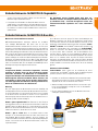
Dieses Modell ist nicht aus Styropor™! Daher sind Verklebungen mit
Weißleim, Polyurethan oder Epoxy nicht möglich.Diese Kleber haften
nur oberächlich und können im Ernstfall abplatzen. Verwenden Sie nur
Cyanacrylat-/Sekundenkleber mittlerer Viskosität, vorzugsweise Zacki2-
ELAPOR
®
# 1-01291, der für ELAPOR
®
Partikelschaum optimierte und
angepasste Sekundenkleber. Bei Verwendung von Zacki2-ELAPOR
®
können Sie auf Kicker oder Aktivator weitgehend verzichten. Wenn
Sie jedoch andere Kleber verwenden, und auf Kicker/Aktivator nicht
verzichten können, sprühen Sie aus gesundheitlichen Gründen nur im
Freien. Vorsicht beim Arbeiten mit allen Cyanacrylatklebern. Diese Kleber
härten u. U. in Sekunden, daher nicht mit den Fingern und anderen
Körperteilen in Verbindung bringen. Zum Schutz der Augen unbedingt
Schutzbrille tragen! Von Kindern fernhalten! An einigen Stellen ist es auch
möglich Heißkleber zu verwenden. Hierauf weisen wir in der Anleitung
ggf. hin!
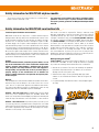
Arbeiten mit Zacki2-ELAPOR
®
Zacki2-ELAPOR
®
wurde speziell für die Verklebung für unsere
Schaummodelle aus ELAPOR
®
entwickelt. Um die Verklebung möglichst
optimal zu gestalten, sollten Sie folgende Punkte beachten:
• Vermeiden Sie den Einsatz von Aktivator. Durch ihn wird die Verbin-
dung deutlich geschwächt. Vor allem bei großächiger Verklebung
empfehlen wir, die Teile 24 Stunden trocken zu lassen.
• Aktivator ist lediglich zum punktuellen Fixieren zu verwenden. Sprü-
hen Sie nur wenig Aktivator einseitig auf. Lassen Sie den Aktivator
ca. 30 Sekunden ablüften.
• Für eine optimale Verklebung rauen Sie die Oberäche mit einem
Schleifpapier (320er Körnung) an.
chenden“ Folgeschäden bei späteren Flügen zu technischem und
Materialversagen und Abstürzen führen.
• Feuergefahr durch Fehlfunktion der Elektronik: Akkus sind sicher
aufzubewahren. Sicherheitshinweise der Elektronikkomponenten im
Modell, des Akkus und des Ladegeräts sind zu beachten. Elektronik
ist vor Wasser zu schützen. Regler und Akkus müssen ausreichend
gekühlt werden.
Die Anleitungen unserer Produkte dürfen nicht ohne aus-
drückliche Erlaubnis der Multiplex Modellsport GmbH & Co. KG
(in schriftlicher Form) - auch nicht auszugsweise in Print- oder
elektronischen Medien reproduziert und / oder veröffentlicht
werden.
# 1-01291
DE

4
Zubehör und Werkzeug
Stückliste
Technische Daten
Benötigtes Zubehör Benötigtes Werkzeug
Spannweite 860mm
Länge über alles 918mm
Fluggewicht 195g
Steuerkanäle
4
RC-Funktionen Höhenruder, Seitenruder, Querruder, Motor
Flugzeit 6 min
• 1x Hitec Indoor Servo Set 2x HS-40 & 1x HS-65HB # 1-01009
• 1x Empfänger RX-5 light M-LINK 2,4 GHz # 55808
• 1x ROXXY EVO LiPo 2 - 450B 30C mit BID-Chip # 1-00016
• 1x Antriebssatz V2 Extra 330 SC Indoor / FunnyCub # 1-01026
• 1x Zacki2-ELAPOR
®
20g # 1-01291
• 1x Zacki2-ELAPOR
®
super liquid # 1-01292
• 1x Zackivator
®
# 1-01032
• UHU
®
POR
• kleiner Kreuzschlitzschraubendreher
• kleiner Schlitzschraubendreher
• Cuttermesser
• Spitzzange
• 1 Bogen Schleifpapier Körnung 320
• 1mm Bohrer
• 1,5mm Bohrer
Stück Bezeichnung Material Abmessungen
1 Slick X360 Indoor Edition Bauanleitung Papier DIN A-4
1 Reklamationsmeldung Modelle Papier DIN A-5
1 Rumpfoberteil EPP Fertigteil
1 Rumpfunterteil EPP Fertigteil
1 Rumpfmittelteil EPP Fertigteil
1 Seitenleitwerk EPP Fertigteil
1 Höhenleitwerk EPP Fertigteil
1 Tragäche links EPP Fertigteil
1 Tragäche rechts EPP Fertigteil
1 Radverkleidung links EPP Fertigteil
1 Radverkleidung rechts EPP Fertigteil
1 Fahrwerksverkleidung links EPP Fertigteil
1 Fahrwerksverkleidung rechts EPP Fertigteil
1 Sporn EPP Fertigteil
2 Flügelpylon EPP Fertigteil
2 Rumpfpylon EPP Fertigteil
DE

5
Stückliste
Stück Bezeichnung Material Abmessungen
1 Motorspant Kunststoff Fertigteil
1 Querruderhebelverlängerung Kunststoff Fertigteil
1 Achsbefestigungswinkel L Kunststoff Fertigteil
1 Achsbefestigungswinkel R Kunststoff Fertigteil
2 Fahrwerksverstärkungen Kunststoff Fertigteil
2 Radverkleidungshalter Kunststoff Fertigteil
2 Abstandshalter für Rad Ø 4mm Kunststoff Fertigteil
2 Rad Ø 27mm Kunststoff Fertigteil
2 Schraube Stahl M2 x 10mm
1 Ruderhorn Seitenruder Kunststoff Fertigteil
1 Ruderhorn Höhenruder Kunststoff Fertigteil
1 Ruderhorn Querruder L Kunststoff Fertigteil
1 Ruderhorn Querruder R Kunststoff Fertigteil
5 Gabelkopf Kunststoff Fertigteil
5 Druckstift für Gabelkopf Messing Ø 1 x 5mm
2 Gewindehülse 1,5mm Messing M2 x 20mm
5 Kugelkopf Kunststoff Fertigteil
5 Schraube für Kugelkopf Stahl M1,5 x 4mm
2 Gewindehülse 0,8mm Messing M2 x 14mm
2 Rohradapterstück Kunststoff Ø 2 x 5mm
10 Gestängehalter klein (Ösen) Kunststoff M1,5 x 4mm
14 Rundstab CFK 0,8 x 500mm
4 Rundstab CFK 1,2 x 300mm
2 4-Kant-Stab CFK 2,5 x 1,5 x 233mm
2 Rundstab CFK 1,5 x 25mm
2 Rundstab CFK 1,5 x 200mm
1 Flach-Prolstab CFK 3 x 0,5 x 280mm
2 Flach-Prolstab CFK 3 x 0,5 x 100mm
2 Flach-Prolstab CFK 3 x 0,5 x 140mm
1 Flach-Prolstab CFK 3 x 0,5 x 120mm
1 Flach-Prolstab CFK 3 x 0,5 x 720mm
1 Flach-Prolstab CFK 3 x 0,5 x 704mm
DE

6
Bauanleitung
Wichtiges vor dem Bau
Überprüfen Sie die gelieferten Teile auf ihre Vollständigkeit mittels der
Stückliste auf Seite 4 und 5.
Wir empfehlen für einen verzugsfreien Aufbau eine saubere und gerade
Unterlage, damit das Modell beim Bau keine Macken bekommt. Decken
Sie die Unterlage unbedingt mit Frischhaltefolie ab, um ein Festkleben
von Bauteilen auf der Unterlage zu vermeiden.
EPP auf EPP Verklebungen werden am besten mit UHU
®
POR durchgeführt.
Dazu wird eine dünne Schicht Klebstoff an die zu verklebenden Teile
gegeben. Diese dann für ca. 10 min. antrocknen lassen. Anschließend
werden die Teile zusammengedrückt. Hierbei kommt es nicht auf
die Dauer des Druckes, sondern auf die Druckstärke an. Wenn CFK
Prolstäbe in das EPP eingelassen werden, wird der Prolstab in den
dafür vorgesehenen Schlitz gedrückt und anschließend dünnüssiger
Zacki-ELAPOR
®
super liquid darüber geträufelt. Diese Klebung kann mit
wenig Aktivatorspray xiert werden. Bei den restlichen Verklebungen
kann normaler Zacki-ELAPOR
®
verwendet werden.
Alle Carbonstäbe, mit Ausnahme der 0,8 x 500mm Carbonstäbe, sind
schon auf die richtige Länge gebracht worden. Bei manchen bereits
abgelängten Stäben kann es allerdings vorkommen, dass diese noch
etwas gekürzt werden müssen. Überprüfen Sie deshalb vor jedem
Klebevorgang die Carbonstäbe auf ihre richtige Länge.
Die 0,8 x 500mm Carbonstäbe liegen unabgelängt bei. Pro Bauabschnitt
ist dann jeweils angegeben, wie viele dieser Stäbe benutzt werden sollen
und noch selbst abzulängen sind. Diese 0,8mm Stäbe sind von 1-14
durchnummeriert. Dabei empehlt es sich, den Carbonstab an der Stelle
anzuhalten und mit einer Zange oder einem Seitenschneider passend
abzulängen. Es liegen dem Bausatz dafür genug Carbonstäbe bei.
Diese geschriebene Anleitung soll nur als Ergänzung zu den Illustrationen
dienen. Alle nur wenig beschriebenen Bauschritte werden dort genauer
erläutert.
Vorbereiten der einzelnen Bauteile
Damit die Ruder im späteren Flugbetrieb leichtgängiger laufen, müssen
alle Ruderklappen vor dem Bau um 180° umgeschlagen werden. In
dieser Position sind sie dann ca. für eine Stunde zu xieren.
Abb. 1
Kleben Sie die Kohlefaser Flachprole in das Höhen- und Seitenleitwerk
ein. Anschließend kleben Sie das Seitenruderhorn in das Seitenruder.
Abb. 2
Kleben Sie die Tragächenhälften, sowie das Höhenleitwerk an das
Rumpf-Mittelstück.
Abb. 3
Kleben Sie die Kohlefaserstäbe zur Verstärkung in die Rumpf-
Unterseite und die untere Rumpfhälfte. Kleben Sie außerdem die EPP-
Kohlestabhalterungen auf die Tragächenunterseite und die 3D-Druck
Fahrwerksverstärkungen auf die untere Rumpfhälfte. Anschließend
kleben Sie das Höhenruderservo (Hitec HS-40 #112040) ein, sodass
dieses bündig mit der Tragächenoberseite abschließt.
Abb. 4
Kleben Sie die untere Rumpfhälfte auf die Rumpfunterseite.
Abb. 5
Kleben Sie die beiden Fahrwerksstäbe ein. Verkleben Sie anschließend
die Kohlefaserstreben wie gezeigt an Rumpf und Tragäche.
Abb. 6
Kleben Sie die Radverkleidungshalter auf die Radverkleidungen. Kleben
Sie anschließend die Fahrwerksbeine und die CFK-Radachsen an die
Achsbefestigungswinkel. Achten Sie dabei auf eine rechte und linke
Seite. Anschließend stecken Sie das Rad und einen Abstandsring auf jede
Achse und sichern Sie den Abstandsring mit etwas Kleber Achten Sie
darauf, dass sich die Räder frei bewegen können. Stecken Sie nun die
Radschuhe auf die Radachsen und kleben die zwei Fahrwerksverkleidungen
an die Fahrwerksbeine.
Abb. 7
Kleben Sie das Querruderservo (Hitec HS-5065MG #113065),
das Seitenruderservo (Hitec HS-40 #112040) und die beiden
Querruderhörner von oben ein. Stellen Sie mit Hilfe eines Servotesters
oder Ihrer Fernsteueranlage das Querruderservo auf neutral.
Verschrauben Sie das dem Servo beiliegende Doppelruderhorn mit der
Servohebelverlängerung. Geeignete Schrauben liegen dem Servobeipack
bei. Bohren Sie die Servohebelverlängerung mit einem Ø 1,5mm Bohrer
auf und schrauben die Kugelköpfe, mit den Kugeln nach oben gerichtet
fest. Verschrauben Sie nun den Servohebel auf dem Servo, dieser zeigt in
Flugrichtung nach vorne.
Montieren Sie die Querruderanlenkung gemäß der Abbildung. An das
eine Ende des CFK-Stabs wird eine M2 x 20mm Gewindehülse geklebt.
Drehen Sie eine Kugelpfanne auf, halten Sie die Gewindehülse dazu
mit einer Zange fest. Ermitteln Sie die Länge zu den Ruderhörnern und
kürzen Sie den Stab auf die passende Länge. Kleben Sie anschließend
die Kugelpfanne fest. Nun können Sie die Gestängelänge mit den
Gewinden noch fein einstellen, sodass beide Querruder waagerecht
stehen. Schrauben Sie nun das Gestänge am Ruderhorn fest, sodass der
Kugelkopf nach innen zeigt.
Abb. 8
Kleben Sie die obere Rumpfhälfte und das Seitenruder an das Rumpf-
Mittelteil.
DE

7
Bauanleitung
Abb. 9
Kleben Sie die restlichen Kohlefaserverstrebungen ein. Kleben sie die
Stäbe dort zusammen, wo sich diese am Leitwerk kreuzen. Kleben Sie
nun die Gestängeführungen, sowie das Höhenruderhorn auf der Oberseite
fest.
Montieren Sie die Seiten- und Höhenruder Anlenkung gemäß der
Abbildung. An das eine Ende des CFK-Stabs wird eine M2 x 14mm
Gewindehülse geklebt. Drehen Sie einen Gabelkopf auf, halten Sie die
Gewindehülse dazu mit einer Zange fest. Fädeln Sie den Stab von vorne
durch die Gestängeführungen und befestigen Sie mit Hilfe einer kleinen
Zange den Gabelkopf mit einem Druckstift am Servohebel. Benutzen
Sie beim Seitenruder-Servohebel am besten das 4. Loch und beim
Höhenruder-Servohebel das 3. Loch von innen.
Pressen Sie das Rohradapterstück in den anderen Gabelkopf ein und
befestigen Sie diesen dann am Ruderhebel. Kürzen Sie den Anlenkstab
auf die richtige Länge und kleben diesen dann in den Gabelkopf am
Ruderhorn ein. Nun können Sie die Gestängelänge mit den Gewinden
noch fein einstellen, sodass das Ruder parallel zum Rumpf steht. Achten
Sie auf eine saubere Verklebung der Anlenkungsteile.
Abb. 10
Kleben Sie den Motorspant an den Rumpf.
Abb. 11
Schrauben Sie den Motor (ROXXY C27-13-1800kV # 1-00018) vorne
an den Motorspant. Die Schrauben entnehmen Sie dem Kleinteilebeutel
aus dem Motorbeipack. Befestigen Sie den Regler (ROXXY BL Control
715 BEC # 1-01050) mit Klettband am Rumpfunterteil. Befestigen Sie
ebenso den Empfänger und den Akku mit etwas Klettband am Rumpf.
Beim Klett des Akkus empehlt es sich, das EPP an der Stelle des
Klettbandes mit etwas UHU
®
POR zu bestreichen und den Kleber 10min
antrocknen zu lassen.
Der Schwerpunkt des Modells ist bei 210mm, gemessen von der
Vorderkante des Motorspants. Die Ruderausschläge sind individuell
einzustellen, es empehlt sich jedoch ca. 80% EXPO auf Querruder und
60% EXPO auf Seiten- und Höhenruder zu mischen.
Sicherheit
Sicherheit ist das oberste Gebot beim Fliegen mit Flugmodellen. Eine
Haftpichtversicherung ist obligatorisch. Falls Sie in einen Verein oder
Verband eintreten, können Sie diese Versicherung dort abschließen.
Achten Sie auf ausreichenden Versicherungsschutz (Modellugzeug mit
Antrieb). Halten Sie Modelle und Fernsteuerung immer absolut in Ordnung.
Informieren Sie sich über die Ladetechnik für die von Ihnen verwendeten
Akkus. Benutzen Sie alle sinnvollen Sicherheitseinrichtungen, die
angeboten werden. Informieren Sie sich in unserem Hauptkatalog oder
auf unserer Homepage www.multiplex-rc.de MULTIPLEX-Produkte
sind von erfahrenen Modelliegern aus der Praxis für die Praxis gemacht.
Fliegen Sie verantwortungsbewusst! Anderen Leuten dicht über die Köpfe
zu iegen ist kein Zeichen für wirkliches Können, der wirkliche Könner hat
dies nicht nötig. Weisen Sie auch andere Piloten in unser aller Interesse
auf diese Tatsache hin. Fliegen Sie immer so, dass weder Sie noch andere
in Gefahr kommen. Denken Sie immer daran, dass auch die allerbeste
Fernsteuerung jederzeit durch äußere Einüsse gestört werden kann.
Auch langjährige, unfallfreie Flugpraxis ist keine Garantie für die nächste
Flugminute.
Wichtig: Prüfen Sie vor jedem Start den sicheren Sitz des Akkus.
Kontrollieren Sie auch die Funktion aller Ruder!
Wir, das MULTIPLEX -Team, wünschen Ihnen beim Bauen und später
beim Fliegen viel Freude und Erfolg.
MULTIPLEX Modellsport GmbH & Co. KG
DE

8
When operating the model, all warning and safety information in
the operating instructions must be observed.
The model is NOT A TOY in the conventional sense. If you use your model
carefully, it will provide you and your spectators with lots of fun without
posing any danger. If you do not operate your model responsibly, this may
lead to signicant property damage and severe injury. You and you alone
are responsible for following the operating instructions and for ensuring
the safety guidelines are adhered to.
When setting up the model, operators declare they are familiar with
and understand the contents of the operating instructions, particularly
regarding safety information, maintenance work, operating restrictions,
and deciencies.
This model may not be operated by children under the age of 14. If minors
operate the model under the supervision of a responsible and competent
adult pursuant to the law, this person is responsible for adhering to the
information in the operating instructions.
THE MODEL AND THE ASSOCIATED ACCESSORIES MUST BE KEPT OUT
OF REACH OF CHILDREN UNDER 3 YEARS OF AGE! CHILDREN UNDER 3
COULD SWALLOW REMOVABLE SMALL PARTS OF THE MODEL. RISK OF
SUFFOCATION!
Multiplex Modellsport GmbH & Co. KG is not liable for loss, damage
and consequential damage of any kind caused by incorrect operation,
improper use or misuse of this product, including the accessories used
along with it.
Proper use
The model may only be used in the hobby sector. No other type of use
is permitted. To operate the model, only the accessories recommended
by Multiplex may be used. The recommended components have been
tested and adjusted for safe functioning together with the model. If other
components are used or the model is modied, all claims against the
manufacturer or retailer are void.
In order to minimize the risk when operating the model, observe the
following points in particular:
• The model is controlled via a remote control. No remote control
is safe from radio interference. Interference may lead to a loss of
control of the model. Therefore, always ensure large safety distanc-
es in all directions when operating the model. As soon as even the
smallest indication of radio interference presents itself, operation of
the model must be halted immediately!
• The model may only be put into operation after a complete function
and range test has been successfully carried out as per the instruc-
tions for the remote control.
• The model may only be own in good visibility. Do not y in poor light
or in the direction of the sun in order to avoid glare.
• The model may not be operated under the inuence of alcohol or
other intoxicants. The same applies for medicines that impair percep-
tion and responsiveness.
• Only y the model in wind and weather conditions in which you can
safely control it. Even with light wind, take into account that turbu-
lence may build up on objects and have an effect on the model.
• Never y in places where this would pose a danger to others, i.e. in
residential areas, near power lines, roads, and railroad tracks.
• Never direct the model at people or animals! Avoid unnecessary risks
and alert other pilots to potential hazards. Always y in a manner that
ensures neither you nor others are exposed to danger – even many
years of accident-free ying experience are no guarantee for the next
minute of ying time.
Residual risks
Even if the model is operated in accordance with the regulations and
observing all safety aspects, there is always a residual risk.
Third-party liability insurance (powered model airplane) is therefore
mandatory. If you are a member of a group or association, you might be
able to take out the appropriate insurance there.
Ensure models and the remote control are properly maintained and are in
good condition at all times.
Due to the construction and design of the model, the following dangers
may arise in particular:
Injuries caused by the propeller: As soon as the battery is connected, the
area around the propeller must be kept clear. Be aware that objects in
front of the propeller may be sucked in and objects behind the propeller
may be blown away. Always align the model ensuring it cannot move in
the direction of other people if the motor starts up unintentionally. When
performing adjustments for which the motor is running or may start up,
the model must always be securely held in place by a helper.
• Crashes caused by control errors: Even the most experienced pilots
can make mistakes. For this reason, only y in a safe environment
and at authorized model airplane ying elds.
• Crashes caused by technical failures, undetected damage from
transportation or pre-existing damage: The model must be carefully
inspected before each ight. Bear in mind that technical or material
failures may occur at any time. Therefore, only operate the model in a
safe environment.
• Adhere to operating limits: Excessively harsh ying weakens the
structure of the model and may lead to technical and material fail-
ures as well as crashes immediately or, due to 'insidious' consequen-
tial damage, in later ights.
• Risk of re due to malfunction of the electronics: Batteries must be
stored safely. The safety information of the electronic components in
the model, the battery, and the charging device must be observed.
Safety information for MULTIPLEX airplane models
EN

9
Familiarize yourself with the construction kit!
MULTIPLEX model kits are subjected to constant material inspection
during production. We hope that you are satised with the contents of the
kit. We nevertheless ask that you check all parts (according to the parts
list) before use, as used parts cannot be exchanged. If a part is not OK,
we will be happy to x or replace it after verifying this. Please send the
part with sufcient postage to our Service department. Be sure to include
a short description of the fault along with the purchase receipt. We are
continuously working on further developing the technology of our models.
We reserve the right to make changes to the contents of the kit in terms
of shape, dimension, technology, material, and equipment at any time and
without warning. Please understand that no claims can be derived from
specications and illustrations in these instructions.
Caution!
Remote-controlled models, particularly airplane models, are not
toys in the conventional sense. Their construction and operation
requires technical understanding, a minimum level of artisan
skills, discipline, and safety-awareness. Errors and negligences
during building and operation may result in personal injury or
property damage. As the manufacturer has no influence on
proper assembly, maintenance, and operation, we explicitly refer
to these dangers.
Warning:
Like any airplane, the model has static limitations! Nosedives and reckless
maneuvers may result in damage to the model. Please note: In such
cases, there is no replacement. Approach the limitations with caution.
The model is tted with the propeller recommended by us but can only
withstand the loads if it is built awlessly and is undamaged.
Crooked – does not really exist. If individual parts are bent during
transit, they can be straightened again. Here, ELAPOR
®
behaves like
metal. If you overbend the material slightly, it springs back minimally and
retains its shape. The material of course has its limits – so don’t overdo it!
Crooked
–
does indeed exist! If you want to paint your model, you do
not need any primer for pretreatment when using the EC colors. Matt
paints result in the best look. Under no circumstances may the paint coats
be too thick or applied unevenly, otherwise the model will go out of shape
and will be crooked, heavy or even unusable!
This model is not made of Styrofoam™! Therefore, adhesions using
white glue, polyurethane or epoxy are not possible. These glues only stick
supercially and may peel off in severe cases. Only use cyanoacrylate/
superglue of medium viscosity, preferably Zacki2-ELAPOR
®
# 85 2727,
the superglue optimized and adapted for ELAPOR
®
particle foam. When
using Zacki2-ELAPOR
®
, you can largely do without kickers or activators.
If, however, you use other adhesives, and are unable to do without
kickers/activators, only spray outdoors for health reasons. Take care when
working with all cyanoacrylate adhesives. These adhesives sometimes
harden in seconds, so do not bring your ngers or other body parts
into contact with them. To protect your eyes, be sure to wear protective
goggles! Keep away from children! In some places, hot glue may also be
used. If applicable, this is indicated in the instructions!
Working with Zacki2 ELAPOR
®
Zacki2 ELAPOR
®
was developed specially for adhesion on our foam
models made of ELAPOR
®
. In order to design the adhesion as optimally
as possible, the following points should be taken into consideration:
• Avoid the use of activators. This causes the bonding to be signicant-
ly weakened. Especially for large-scale adhesion, we recommend
allowing 24 hours for the parts to dry.
• Activators must only be used for point xing. Only spray a little
activator on one side. Allow the activator to ash off for approx. 30
seconds.
• For optimal bonding, sand down the surface using sandpaper (grain
size 320).
The electronics must be protected from water. The controller and the
batteries must be sufciently cooled.
The instructions of our products may not be reproduced and/or
published – not even in part – in print or electronic media without
the express (written) permission of Multiplex Modellsport GmbH
& Co. KG.
Safety information for MULTIPLEX construction kits
# 1-01291
Safety information for MULTIPLEX airplane models
EN

10
Accessories and tools
List of parts
Specications
Required accessories Required tool
Wingspan 860mm
Overall length 918mm
Flight weight 195g
Channels
4
RC functions Elevator, rudder, aileron, motor, vector
Flight time 6 minutes
• 1x Hitec Indoor servo kit 2x HS-40 & 1x HS-65HB # 1-01009
• 1x Receiver RX-5 light M-LINK 2.4 GHz # 55808
• 1x ROXXY EVO LiPo 2 - 450B 30C with BID chip # 1-00016
• 1x Power kit V2 Extra 330 SC Indoor / FunnyCub # 1-01026
• 1x Zacki2-ELAPOR
®
20g # 1-01291
• 1x Zacki2-ELAPOR
®
super liquid # 1-01292
• 1x Zackivator
®
# 1-01032
• UHU
®
POR
• Small cross-tip screwdriver
• Small slotted screwdriver
• Cutter
• Pointed pliers
• 1 sheet of 320 grit sandpaper
• 1mm drill bit
• 1.5mm drill bit
Qty. Name Material Dimensions
1 Slick 360 Indoor Edition assembly instructions Paper DIN A-4
1 Complaints form for models Paper DIN A-5
1 Upper fuselage section EPP Finished component
1 Lower fuselage section EPP Finished component
1 Center fuselage section EPP Finished component
1 Vertical tail EPP Finished component
1 Tailplane EPP Finished component
1 Left wing EPP Finished component
1 Right wing EPP Finished component
1 Wheel cover, left EPP Finished component
1 Wheel cover, right EPP Finished component
1 Undercarriage cover, left EPP Finished component
1 Undercarriage cover, right EPP Finished component
1 Tailskid EPP Finished component
2 Wing pylon EPP Finished component
2 Fuselage pylon EPP Finished component
EN

11
List of parts
Qty. Name Material Dimensions
1 Bulkhead Plastic Finished component
1 Aileron horn extension Plastic Finished component
1 Axle retaining bracket L Plastic Finished component
1 Axle retaining bracket R Plastic Finished component
2 Undercarriage reinforcement Plastic Finished component
2 Wheel cover holder Plastic Finished component
2 Spacer for Ø 4mm wheel Plastic Finished component
2 Ø 27mm wheel Plastic Finished component
2 Screw Steel M2 x 10mm
1 Rudder horn, rudder Plastic Finished component
1 Rudder horn, elevator Plastic Finished component
1 Rudder horn, aileron L Plastic Finished component
1 Rudder horn, aileron R Plastic Finished component
5 Fork head Plastic Finished component
5 Clevis pin for fork head Brass Ø 1 x 5mm
2 Threaded coupler 1.5mm Brass M2 x 20mm
5 Ball head Plastic Finished component
5 Screw for ball head Steel M1.5 x 4mm
2 Threaded coupler 0.8mm Brass M2 x 14mm
2 Tube adapter Plastic Ø 2 x 5mm
10 Small rod holder (eyelets) Plastic M1.5 x 4mm
14 Round rod CFRP 0.8 x 500mm
4 Round rod CFRP 1.2 x 300mm
2 Square rod CFRP 2.5 x 1.5 x 233mm
2 Round rod CFRP 1.5 x 25mm
2 Round rod CFRP 1.5 x 200mm
1 Flat section rod CFRP 3 x 0,5 x 280mm
2 Flat section rod CFRP 3 x 0,5 x 100mm
2 Flat section rod CFRP 3 x 0,5 x 140mm
1 Flat section rod CFRP 3 x 0,5 x 120mm
1 Flat section rod CFRP 3 x 0,5 x 720mm
1 Flat section rod CFRP 3 x 0,5 x 704mm
EN

12
Assembly instructions
Important info before you start assembling
Use the list of components on page 4 and 5 to check the completeness
of the components supplied.
We recommend assembling the model on a clean and perfectly at surface
to ensure that the structure is free of warps and that the components are
not damaged during assembly. Be sure to cover the surface with clear
plastic lm to avoid the components sticking to the surface.
Joints between EPP components are best made using UHU
®
POR. In this
case, apply a thin lm of adhesive to both surfaces to be glued. Then
allow it to air-dry for about ten minutes. Then press the parts together.
The strength of the joint is determined by the pressure you exert, rather
than the length of time you exert it. When CFRP section rods have to be
inserted into EPP parts, press the section rods into the appropriate slot,
then trickle low-viscosity (thin) Zacki-ELAPOR
®
super liquid onto them. A
small amount of activator spray will help to harden the adhesive. All other
glued joints can be made using standard Zacki-ELAPOR
®
.
All carbon rods, with the exception of the 0.8 x 500mm carbon rods, are
supplied cut to length. Although the rods are supplied cut to length, you
may need to trim them slightly. Therefore, make sure the carbon rods are
the correct length before gluing them into place.
The supplied 0.8 x 500mm carbon rods have not been cut to length.
For each assembly stage, it is then specied how many of these rods
are to be used and still have to be cut to length. These 0.8mm rods are
numbered 1-14. We recommend that you hold the carbon rod in position,
and cut it to length using pliers or side-cutters. The kit includes an ample
supply of carbon rods.
These written instructions are intended only as a supplement to the
illustrations. All briey described assembly steps are explained in more
detail there.
Preparing the individual components
To ensure the rudders move freely when the model is ying, fold all rudder
aps through 180° prior to assembly. Then leave them in this position for
about an hour.
Fig. 1
Glue the carbon ber at sections into the elevator and the vertical tail.
Then glue the rudder horn into the rudder.
Fig. 2
Glue the wing halves and the tailplane to the center fuselage section.
Fig. 3
To ensure reinforcement, glue the carbon ber rods into the underside
of the fuselage and into the lower fuselage section. Further, glue the
EPP carbon rod holders to the underside of the wing and the 3D-printed
undercarriage reinforcements to the lower fuselage section. Then glue the
elevator servo (Hitec HS-40 #112040) into place, making sure it is ush
with the upper surface of the wing.
Fig. 4
Glue the lower fuselage section to the underside of the fuselage.
Fig. 5
Glue the two undercarriage rods into place. Subsequently glue the carbon
ber struts to the fuselage and the wing as shown.
Fig. 6
Glue the wheel cover holders to the wheel covers. Then glue the
undercarriage legs and the CFRP wheel axles to the axle retaining
brackets. Remember to make one right-hand and one left-hand assembly.
Now t each wheel on its axle followed by a spacer ring, and glue the
spacer rings into place with a small amount of adhesive.
Check that the wheels are free to rotate. Now place the wheel caps on the
wheel axles and glue the two undercarriage covers to the undercarriage
legs.
Fig. 7
Glue the aileron servo (Hitec HS-5065MG #113065), the rudder servo
(Hitec HS-40 #112040) and the two aileron horns into place from above.
Use a servo tester or your radio control system to set the aileron servo
to neutral.
Then screw the double rudder horn to the servo arm extension. Suitable
screws are supplied in the servo accessory pack. Open up the servo arm
extension using a 1.5mm drill bit and screw the ball heads into place with
the balls facing upward. Now screw the servo arm onto the servo, making
sure it points forward in the direction of ight.
Assemble the aileron linkage as shown in the illustration. Attach an M2
x 20mm threaded coupler to one end of the CFRP rod. Screw a ball
socket onto the threaded coupler, holding the threaded coupler in pliers
to prevent it turning. Determine the length to the rudder horns and cut
the rod to the correct length. Then glue the ball socket into place. You
can now ne-tune the pushrod length using the threads; ensuring both
ailerons are horizontal. Now screw the pushrod onto the rudder horn,
making sure the ball head points inward.
Fig. 8
Glue the upper fuselage section and the rudder to the center fuselage
section.
EN

13
Assembly instructions
Fig. 9
Glue the two remaining carbon ber struts into place. Glue the rods
together at the point where they cross over at the elevator. Now glue the
pushrod guides and the elevator horn into place on the upper side.
Assemble the rudder and elevator linkage as shown in the illustration.
Attach an M2 x 14mm threaded coupler to one end of the CFRP rod.
Screw a fork head onto the threaded coupler, holding the threaded coupler
in pliers to prevent it turning. Thread the rod through the pushrod guides
from the front and attach the fork head to the servo arm by pressing a
clevis pin through it with small pliers. It is best to use the 4th hole for the
rudder servo arm and the 3rd hole from the inside for the elevator servo
arm.
Press the tube adapter into the other fork head and then attach it to the
rudder arm. Shorten the linkage rod to the correct length and glue it into
the fork head on the rudder horn. You can now ne-tune the pushrod
length using the threads; ensuring the rudder is parallel to the fuselage.
Make sure the linkage parts are glued properly.
Fig. 10
Glue the bulkhead to the fuselage.
Fig. 11
Screw the motor (ROXXY C27-13-1800kV # 1-00018) at the front
to the bulkhead. Use the screws from the small parts bag in the motor
accessory pack. Use hook-and-loop tape to attach the speed controller
(ROXXY BL Control 715 BEC # 1-01050) to the lower fuselage section.
Also attach the receiver and ight battery to the fuselage using small
pieces of hook-and-loop tape. When attaching the tape to the battery, we
recommend the application of a small amount of UHU
®
POR at the point
where the hook-and-loop tape is to be used, and allow it to air-dry for
about ten minutes.
The model’s center of gravity is 210mm, measured from the leading edge
of the bulkhead. The rudder deections can be set to the pilot’s individual
preference, but we recommend about 80% EXPO on ailerons and 60%
EXPO on rudders and elevators.
Safety
Safety is the top priority when ying any model aircraft. Third-party liability
insurance is mandatory. If you become a member of a model club or
an association, suitable insurance cover might be available through the
club/association. It is your personal responsibility to ensure sufcient
insurance cover (powered model airplane). Ensure models and the RC
unit are properly maintained and are in good working condition at all
times. Check the correct charging procedure for the batteries used.
Make use of all the safety systems and precautions recommended.
Find relevant information in our main catalog or on our website
www.multiplex-rc.de MULTIPLEX products are designed and
manufactured exclusively by experienced practicing modelers for other
practicing modelers. Always y models responsibly! Flying models low
over other people’s heads is denitely not proof of your piloting skill, as
good pilots would never do this. Remember to point out this fact to other
model pilots in the interest of everyone’s safety. Always y in such a way
that you do not endanger yourself or others. Bear in mind that even the
best RC system in the world is subject to outside interference. No matter
how many years of accident-free ying you have under your belt, you
have no idea what will happen in the next minute.
Important: Check that the battery is fastened securely prior to each
start. Make sure all the rudders are working properly!
The MULTIPLEX team wishes you lots of enjoyment and success in
assembling and ying your model.
MULTIPLEX Modellsport GmbH & Co. KG
EN

14
Conseils de sécurité pour les modèles volants MULTIPLEX
Lors de l’utilisation de ce modèle, veuillez respecter impérative-
ment tous les avertissements et consignes de sécurité.
Ce modèle N’EST PAS UN JOUET au sens propre du terme. Utilisez votre
modèle avec sérieux et prudence. Vous ferez ainsi le bonheur de vos
spectateurs sans provoquer de dangers. L’utilisation irraisonnée de ce
modèle peut entraîner des dommages matériels majeurs et des blessures
graves. Charge à vous de suivre cette notice de construction et de mettre
en pratique les consignes de sécurité.
En utilisant son modèle, l’utilisateur déclare avoir pris connaissance et
compris le contenu de cette notice, notamment à propos des consignes
de sécurité, travaux de maintenance, limitations d’utilisation et défauts.
Ce modèle ne peut être utilisé par des enfants de moins de 14 ans. En
cas d’utilisation du modèle par un mineur sous la surveillance d’un adulte
responsable et bien informé au sens de la législation, ce dernier répond
de l’application des consignes gurant dans cette notice.
VEUILLEZ TENIR CE MODÈLE ET SES ACCESOIRES HORS DE PORTÉE
DES ENFANTS DE MOINS DE 3 ANS ! LES ENFANTS DE MOINS DE 3 ANS
POURRAIENT AVALER LES PETITES PIÈCES AMOVIBLES DU MODÈLE.
RISQUE D’ÉTOUFFEMENT !
Multiplex Modellsport GmbH & Co. KG décline toute responsabilité en cas
de perte, dommages et dommages consécutifs de toute nature, dus à une
utilisation erronée, à une utilisation non conforme ou inappropriée de ce
produit, y compris les accessoires utilisés avec ce dernier.
Utilisation conforme
Ce modèle est exclusivement destiné à être utilisé pour les loisirs. Toute
autre utilisation est interdite. Ce modèle ne peut être utilisé qu’avec
les accessoires recommandés par Multiplex. En effet, les composants
recommandés ont été testés et adaptés au modèle pour assurer un
fonctionnement en toute sécurité. L’utilisation d’autres composants ou
la modication du modèle entraîne l’extinction de toute prétention auprès
du fabricant, resp. distributeur.
Pour minimiser le risque lié à l’utilisation du modèle, veuillez respecter
les points suivants :
• Ce modèle se pilote à l’aide d’une radiocommande. Aucune ra-
diocommande n’est entièrement protégée contre les interférences.
Les interférences peuvent entraîner la perte de contrôle du modèle.
Par conséquent, veillez à toujours utiliser votre modèle dans des
espaces entourés d’un grand périmètre de sécurité dans toutes les
directions. Au moindre signe d’interférences, veuillez arrêter immé-
diatement de piloter votre modèle !
• Ensuite, ne réutilisez votre modèle qu’après avoir effectué un contrôle
exhaustif et concluant des fonctions et de la portée de la radiocom-
mande en suivant les instructions fournies avec cette dernière.
• Veuillez piloter ce modèle uniquement si la visibilité est bonne. Ne le
pilotez pas si les conditions de lumière sont difciles et vers le soleil,
cela an d’éviter tout éblouissement.
• Ne pilotez pas ce modèle si vous êtes sous l’emprise de l’alcool et
d’autres stupéants. Ne le pilotez pas non plus si vous prenez des
médicaments limitant votre capacité de perception et vos réexes.
• Ne pilotez votre modèle que dans des conditions de vent et météo
vous permettant de bien le maîtriser. Lorsque le vent est faible,
n’oubliez pas que des turbulences peuvent se former et inuer sur
votre modèle.
• Ne pilotez jamais où vous pourriez vous mettre en danger ou mettre
en danger autrui (par ex. dans des zones d’habitation et près de
lignes haute tension, routes et voies ferrées).
• Ne dirigez jamais votre modèle vers des personnes et des animaux !
Évitez de prendre des risques inutiles et prévenez les autres pilotes
en cas de danger. Pilotez toujours en veillant à ne pas vous mettre en
danger ni à mettre en danger autrui – une expérience de vol de longue
date et sans accident n’est pas une garantie pour votre prochaine
minute de vol.
Risques résiduels
Un risque résiduel persiste même en cas d’utilisation conforme et de
respect de toutes les consignes de sécurité.
Raison pour laquelle vous devez obligatoirement souscrire une assurance
responsabilité civile (aéromodélisme motorisé). Si vous êtes membre
d’un club ou d’une fédération, vous pourrez éventuellement y souscrire
l’assurance correspondante.
Veillez à tout moment au bon entretien et au bon état de fonctionnement
de vos modèles et de votre radiocommande.
Selon son type de construction et sa version, un modèle peut notamment
présenter les risques suivants :
Blessures dues à l’hélice : dès que la batterie est branchée, tenez-vous à
l’écart de la zone d’évolution de l’hélice. Veuillez noter que les objets situés
devant l’hélice sont aspirés et ceux situés derrière, repoussés. Orientez
toujours le modèle de sorte à ce qu’il ne se dirige pas vers les personnes
en cas d’allumage intempestif du moteur. Lors des réglages, moteur en
marche ou pouvant démarrer, demandez toujours à un assistant de tenir
fermement le modèle.
• Crash dû à une erreur de pilotage : même les pilotes les plus aguer-
ris peuvent commettre des erreurs. Volez toujours dans un environ-
nement sûr et sur des terrains autorisés pour le modélisme aérien.
• Crash dû à un problème technique ou à une avarie de transport
/ dommage précédent non détecté : veuillez contrôler avec soins
le modèle avant chaque vol. N’oubliez jamais que des problèmes
techniques ou matériels peuvent se produire à tout moment. Par
conséquent, volez toujours le modèle dans un environnement sûr.
• Respecter les limites : les manœuvres trop brutales affaiblissent la
structure du modèle et peuvent entraîner, soudainement ou en raison
de dommages «latents», des problèmes techniques et des crashs
lors des vols suivants.
• Risque d’incendie dû à une défaillance de l’électronique : conservez
FR

15
Conseils de sécurité pour les modèles volants MULTIPLEX
Conseils de sécurité pour les kits de construction MULTIPLEX
Familiarisez-vous avec le kit d’assemblage !
Les kits d’assemblages MULTIPLEX sont soumis pendant la production
à des contrôles réguliers du matériel. Nous espérons que le contenu
du kit répond à vos attentes. Nous vous prions néanmoins de vérier le
contenu (suivant la liste des pièces) du kit avant l’assemblage, car les
pièces utilisées ne sont pas échangées. Dans le cas où une pièce ne
serait pas conforme, nous sommes disposés à la rectier ou à l’échanger
après contrôle. Veuillez retournez la pièce à notre service sans omettre de
joindre le ticket de caisse ainsi qu’une brève description du défaut. Nous
travaillons en permanence à l’évolution technique de nos modèles. Nous
nous réservons le droit de modier leurs forme, dimensions, technologie,
matériel et équipement sans préavis. Par conséquent, les informations
et les illustrations gurant dans cette notice ne sauraient faire l’objet de
réclamations.
Attention !
Les modèles radiocommandés, surtout volants, ne sont pas
des jouets au sens propre du terme. Leur assemblage et leur
utilisation exigent des connaissances technologiques et un
minimum de dextérité manuelle, de discipline et de respect de
la sécurité. Les erreurs et négligences, lors de la construction
ou de l’utilisation, peuvent conduire à des dommages corporels
ou matériels. Le fabricant du kit n’ayant aucune influence sur
l’assemblage, l’entretien et l’utilisation correcte du modèle, nous
attirons expressément votre attention sur ces dangers.
Avertissement :
Comme tout avion, ce modèle a ses limites liées aux lois physiques !
Les vols en piqué et les manœuvres périlleuses peuvent entraîner la
destruction du modèle. Note : Dans ces cas, nous n’assurerons pas de
remplacement. Veuillez tester les limites du modèle avec précaution.
Ce modèle est conçu pour le moteur que nous recommandons, mais il
ne pourra résister aux contraintes liés au vol que s’il est correctement
assemblé et non endommagé.
Une pièce tordue ? C’est pratiquement impossible. Si certaines
pièces ont été tordues, par exemple pendant le transport, vous pouvez
les redresser. En effet, la matière ELAPOR
®
se comporte plus ou moins
comme le métal. Si vous la tordez légèrement par excès, elle se redresse
par effet ressort et retrouve sa forme initiale. Bien entendu, elle a aussi
ses limites – veillez donc à ne pas exagérer !
Une pièce tordue
?
C’est possible dans certaines conditions ! Si
vous voulez peindre votre modèle, vous n’avez pas besoin d’apprêter
le support si vous utilisez des peintures EC-Color. Esthétiquement,
les peintures mates donnent les meilleurs résultats. En aucun cas les
couches de peinture devront être trop épaisses ou irrégulières. À défaut,
le modèle se dilatera, se cintrera et deviendra lourd, voire inutilisable !
Ce modèle n’est pas réalisé en polystyrène expansé ! Par conséquent,
les assemblages à la colle blanche, polyuréthane ou époxy ne sont pas
possibles. Ces colles n’adhèrent qu’en surface et peuvent éclater en
cas de fortes contraintes. Veuillez n’utiliser que de la colle cyanocrylate/
instantanée de viscosité moyenne, de préférence la Zacki2 ELAPOR
®
# 85 2727, la colle instantanée optimiséepour la mousse de particules
ELAPOR
®
. Avec la colle Zacki2 ELAPOR
®
, l’utilisation d’un accélérateur
ou d’un activateur n’est pas nécessaire. Si néanmoins, vous utilisez une
autre colle associée à un accélérateur/activateur, pour votre santé veillez
à le vaporiser à l’extérieur. Soyez attentif lors de l’utilisation des colles
cyanocrylates. En effet, celles-ci durcissant en quelques secondes vous
devez éviter d’en mettre sur les doigts et sur d’autres parties du corps.
Pour protéger vos yeux, portez impérativement des lunettes ! Tenez-les
hors de portée des enfants ! Pour certains assemblages, vous pouvez
aussi utiliser une colle à chaud. Dans ce cas, veuillez vous référer à la
notice !
Utilisation de la colle Zacki2 ELAPOR
®
La colle Zacki2 ELAPOR
®
a été spécialement développée pour nos
modèles en mousse ELAPOR
®
. Pour optimiser le collage, veuillez
respecter les points suivants :
• N’utilisez aucun activateur. Celui-ci affaiblirait considérablement la
solidité de l’assemblage. Nous recommandons un temps de séchage
de 24 heures surtout pour les collages de grandes surfaces.
• N’utilisez l’activateur que pour une xation ponctuelle. Vaporisez-le
en faibles quantités et sur une seule face. Laissez sécher l’activateur
env. 30 secondes.
• Pour un collage optimal, dépolissez la surface avec du papier de
verre (grain 320).
les batteries dans un endroit sûr. Respectez les consignes de sécuri-
té relatives aux composants électroniques du modèle, de la batterie
et du chargeur. Protégez l’électronique de l’eau. Laissez bien refroidir
le variateur et les batteries.
La reproduction et / ou la publication, même partielle, des
notices relatives à nos produits, dans des médias imprimés ou
électroniques, est interdite sans l’autorisation expresse (écrite)
Multiplex Modellsport GmbH & Co. KG.
# 1-01291
FR

16
Accessoires et outils
Nomenclature
Caractéristiques techniques
Accessoires requis Outils requis
Envergure 860mm
Longueur hors tout 918mm
Masse en vol 195g
Voies de commande
4
Fonctions RC Profondeur, dérive, ailerons, moteur,
propulsion vectorielle
Temps de vol 6 mn
• 1x Kit servos Hitec Indoor Set 2x HS-40 & 1x HS-65HB
Réf. 1-01009
• 1x Récepteur RX-5 light M-LINK 2,4 GHz Réf. 55808
• 1x ROXXY EVO LiPo 2 - 450B 30C avec puce BID Réf. 1-00016
• 1x Motorisation V2 Extra 330 SC Indoor / FunnyCub Réf. 1-01026
• 1x Zacki2-ELAPOR
®
20g Réf. 1-01291
• 1x Zacki2-ELAPOR
®
super liquid Réf. 1-01292
• 1x Zackivator
®
Réf. 1-01032
• UHU
®
POR
• Petit tournevis cruciforme
• Petit tournevis plat
• Cutter
• Pince à bec
• 1 feuille de papier de verre grain 320
• Foret 1mm
• Foret 1,5mm
Qté Désignation Matière Dimensions
1 Notice de montage Slick 360 Indoor Edition Papier DIN A-4
1 Modèles d’avis de réclamation Papier DIN A-5
1 Partie supérieure du fuselage EPP Complet
1 Partie inférieure du fuselage EPP Complet
1 Partie centrale du fuselage EPP Complet
1 Dérive EPP Complet
1 Empennage EPP Complet
1 Aile gauche EPP Complet
1 Aile droite EPP Complet
1 Carénage de roue gauche EPP Complet
1 Carénage de roue droite EPP Complet
1 Carénage de train gauche EPP Complet
1 Carénage de train droite EPP Complet
1 Patin de queue EPP Complet
2 Mât de l’aile EPP Complet
2 Mât du fuselage EPP Complet
FR

17
Nomenclature
Qté Désignation Matière Dimensions
1 Support moteur Plastique Complet
1 Rallonge tringle d’aileron Plastique Complet
1 Équerre de xation d’axe G Plastique Complet
1 Équerre de xation d’axe D Plastique Complet
2 Renfort train Plastique Complet
2 Support carénage roue Plastique Complet
2 Bague d’espacement roue Ø 4mm Plastique Complet
2 Roue Ø 27mm Plastique Complet
2 Vis Acier M2 x 10mm
1 Guignol dérive Plastique Complet
1 Guignol profondeur Plastique Complet
1 Guignol aileron G Plastique Complet
1 Guignol aileron D Plastique Complet
5 Chape Plastique Complet
5 Tige pour chape Laiton Ø 1 x 5mm
2 Douille letée 1,5mm Laiton M2 x 20mm
5 Rotule Plastique Complet
5 Vis pour rotule Acier M1,5 x 4mm
2 Douille letée 0,8mm Laiton M2 x 14mm
2 Adaptateur tube Plastique Ø 2 x 5mm
10 Support de tringle petit (œillets) Plastique M1,5 x 4mm
14 Tige ronde PRFC 0,8 x 500mm
4 Tige ronde PRFC 1,2 x 300mm
2 Tige carrée PRFC 2,5 x 1,5 x 233mm
2 Tige ronde PRFC 1,5 x 25mm
2 Tige ronde PRFC 1,5 x 200mm
1 Tige ronde PRFC 3 x 0,5 x 280mm
2 Prolé plat PRFC 3 x 0,5 x 100mm
2 Prolé plat PRFC 3 x 0,5 x 140mm
1 Prolé plat PRFC 3 x 0,5 x 120mm
1 Prolé plat PRFC 3 x 0,5 x 720mm
1 Prolé plat PRFC 3 x 0,5 x 704mm
FR

18
Notice de montage
Points importants avant le montage
Veuillez vérier qu’aucune pièce ne manque à l’aide de la nomenclature
gurant en pages 4 et 5.
Nous vous recommandons de travailler sur une surface lisse, propre
et plane pour éviter tout assemblage décalé ou défectueux. Veuillez
impérativement couvrir le plan de travail avec un lm étirable, an d’éviter
le collage des pièces sur le support.
Pour coller les pièces en EPP sur de l’EPP, veuillez utiliser de préférence
la colle UHU
®
POR. Veuillez pour cela appliquer une mince couche de
colle sur les pièces à assembler. Ensuite, laissez sécher la colle pendant
env. 10 mn. Enn, collez les pièces ensemble en pressant. L’essentiel est
de presser les pièces sufsamment fort, non pas de les presser pendant
longtemps. Lorsque vous devez introduire un prolé PRFC dans de l’EPP,
enfoncez le prolé dans son logement puis appliquez de la colle uide
Zacki-ELAPOR
®
super liquid dessus. Vous pouvez ensuite xer ce collage
avec un peu d’activateur en aérosol. Pour les autres collages, vous pouvez
utiliser de la colle Zacki-ELAPOR
®
normale.
Toutes les tiges en carbone, à l’exception de la tige 0,8 x 500mm, sont
déjà à la bonne longueur. Toutefois, il se peut que vous deviez quand
même raccourcir un peu certains d’entre elles. Avant tout collage, veuillez
donc vérier la bonne longueur des tiges en carbone.
Les tiges en carbone 0,8 x 500mm sont fournies non recoupées à
longueur. À chaque étape du montage, la notice vous indique le nombre de
tiges à utiliser et celles que vous devez encore recouper à longueur. Ces
tiges de 0,8mm sont numérotées de 1à14. Nous vous recommandons
de les saisir à cet endroit et de les recouper à longueur avec une pince
ou une pince coupante. Le kit contient un nombre sufsant de tiges en
carbone.
La notice écrite ne sert que de complément aux illustrations. Les étapes du
montage peu détaillées dans le texte sont précisées sur les illustrations.
Préparation des pièces
Pour adoucir le fonctionnement des gouvernes en vue du vol, vous devrez
toutes les retourner à 180°. Bloquez-les ensuite dans cette position
pendant env. 1 heure.
Fig. 1
Collez les prolés plats en bre de carbone sur l’empennage et sur la
dérive. Ensuite, collez le guignol de dérive sur la dérive.
Fig. 2
Collez les ailes et l’empennage à la partie centrale du fuselage.
Fig. 3
Collez les tiges de renfort en bre de carbone sur le bas du fuselage et
sur la moitié inférieure du fuselage. Collez aussi les supports de tiges en
carbone en EPP sur le dessous des ailes et les renforts 3D du train sur
la moitié inférieure du fuselage. Ensuite, collez le servo de la gouverne
de profondeur (Hitec HS-40 #112040) de sorte à ce qu’il afeure à la
surface supérieure de l’aile.
Fig. 4
Collez la moitié inférieure du fuselage sur le bas du fuselage.
Fig. 5
Collez les deux tiges du train. Ensuite, collez les haubans en bre de
carbone au fuselage et à l’aile comme indiqué sur l’illustration.
Fig. 6
Collez les supports de carénage sur chaque carénage de roue. Ensuite,
collez les jambes de train d’atterrissage et les axes de roues PFRC aux
équerres de xation. Veillez à respecter le bon côté (droite et gauche).
Ensuite, insérez une roue et une bague d’écartement sur chaque axe et
bloquez les bagues avec un peu de colle. Veillez
à ce que les roues puissent tourner librement. Fixez à présent les
carénages de roues sur les axes de roues et collez les deux caches sur
les jambes du train.
Fig. 7
Collez le servo d’aileron (Hitec HS-5065MG #113065), le servo de
dérive (Hitec HS-40 #112040) et les deux guignols d’ailerons par le
haut. Mettez le servo d’aileron sur neutre à l’aide d’un testeur de servos
ou de votre radiocommande.
Vissez le guignol double fourni avec le servo à la rallonge de palonnier. Les
vis adéquates sont fournies avec le servo. Percez la rallonge de palonnier
avec un foret Ø 1,5mm et vissez les rotules (orientées vers le haut). Enn,
vissez le palonnier (orienté vers l’avant dans le sens du vol) au servo.
Montez la commande des ailerons comme indiqué sur l’illustration.
À l’une des extrémités de la tige PFRC, collez une douille letée M2 x
20mm. Vissez-y une cavité sphérique en tenant la douille avec une pince.
Mesurez la longueur de la tige jusqu’aux guignols et recoupez-la à la
longueur adéquate. Collez ensuite la cavité sphérique. Vous pouvez à
présent jouer sur les letages pour que les ailerons soient à l’horizontale.
Vissez à présent la tringle sur le guignol (la rotule orientée vers l’intérieur).
Fig. 8
Collez la partie supérieure du fuselage et la dérive sur la partie centrale
du fuselage.
FR

19
Notice de montage
Fig. 9
Collez les tiges de renfort en carbone restantes. Collez les tiges là où
elles se croisent dans l’empennage. Enn, collez les guides de tringle et
le guignol de profondeur sur le dessus.
Montez les commandes de dérive et de profondeur comme indiqué sur
l’illustration. À l’une des extrémités de la tige PFRC, collez une douille
letée M2 x 14mm. Vissez-y une chape en tenant la douille avec une
pince. Enlez la tige par l’avant à travers les guides de tringle et xez
la chape au palonnier du servo à l’aide d’une cheville en vous aidant
d’une petite pince. De préférence, utilisez le 4
e
trou du palonnier du servo
de dérive et le 3
e
trou du palonnier du servo de profondeur à partir de
l’intérieur.
Pressez l’adaptateur de tube dans l’autre chape et xez cette dernière
au palonnier. Recoupez à longueur la tringle de commande avant de la
coller dans la chape xée au palonnier. Vous pouvez à présent jouer sur
les letages pour que la gouverne soit parallèle au fuselage. Veillez à la
propreté du collage des éléments de commande.
Fig. 10
Collez le support moteur au fuselage.
Fig. 11
Vissez le moteur (ROXXY C27-13-1800kV # 1-00018) à l’avant sur le
support moteur. Utilisez pour cela les vis contenues dans le sachet de
fournitures joint au moteur. Fixez le variateur (ROXXY BL Control 715
BEC # 1-01050) dans la partie inférieure du fuselage avec une bande
Velcro. Fixez aussi le récepteur et l’accu dans le fuselage avec un morceau
de bande Velcro. Pour xer l’accu, nous recommandons d’appliquer un
peu de colle UHU
®
POR sur la partie en EPP où sera collée la bande Velcro
et de laisser sécher la colle pendant 10 mn.
Le centre de gravité du modèle est à 210mm, mesurés à partir de l’arête
avant du support moteur. Les débattements sont à régler individuellement.
Il est néanmoins recommandé de mettre 80% EXPO sur les ailerons et de
mixer dérive et profondeur avec 60% EXPO.
Sécurité
La sécurité est la première des priorités lorsque vous pilotez un modèle.
La souscription d’une assurance responsabilité civile est obligatoire. Si
vous êtes membre d’un club ou d’une fédération, vous pourrez y souscrire
la police correspondante. Veillez à ce que la couverture d’assurance
soit sufsante (aéromodélisme motorisé) Veillez à tout moment au bon
état de fonctionnement de vos modèles et de votre radiocommande.
Informez-vous sur la technique de charge des accus que vous utilisez.
Faites usage de tous les dispositifs de sécurité utiles dont vous disposez.
Informez-vous, en consultant notre catalogue général ou notre page web
www.multiplex-rc.de. Les produits MULTIPLEX sont conçus par des
pilotes expérimentés dans la pratique et pour la pratique. Pilotez votre
modèle en toute responsabilité! Voler à ras de la tête des spectateurs
n’est pas une preuve de votre expertise en pilotage. Les vrais experts
n’expriment pas le besoin de le faire. Dans l’intérêt de tous, veuillez
également transmettre ce message aux autres pilotes. Pilotez toujours
en veillant à ne pas vous mettre en danger ni à mettre en danger
autrui. N’oubliez pas que le fonctionnement de la plus performante
des radiocommandes peut aussi être remis en cause par des agents
extérieurs. Une expérience de vol de longue date et sans accident n’est
pas non plus une garantie pour votre prochaine minute de vol.
Important: Avant chaque vol, vériez la bonne xation de l’accu.
Contrôlez aussi le bon fonctionnement de toutes les gouvernes!
L’équipe MULTIPLEX vous souhaite beaucoup de plaisir et de succès dans
la construction et le pilotage de votre modèle.
MULTIPLEX Modellsport GmbH & Co. KG
FR

20
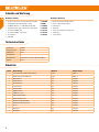
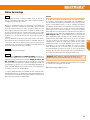
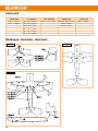
Carbon parts
Abb. / Fig. 1 Abb. / Fig. 2
Abb. / Fig. 3
1,5mm round 3x 0,5mm flat 2,5 x 1,5mm flat 0,8mm round 1,2mm round
2x 1,5 x 25mm 2x 3 x O,5 x 14Omm 2x 2,5 x 1,5 x 233mm 14x O,8 x 5OOmm (1-14) 4x 1,2 x 3OOmm
2x 1,5 x 2OOmm 1x 3 x O,5 x 28Omm 1x O,8 x 69Omm
1x 3 x O,5 x 12Omm 2x O,8 x 444mm
1x 3 x O,5 x 72Omm
1x 3 x O,5 x 7O4mm
2x 3 x O,5 x 1OOmm
Abbildungen · Illustrations · Illustrazioni
Seite laden ...
Seite laden ...
Seite laden ...
Seite laden ...
-
 1
1
-
 2
2
-
 3
3
-
 4
4
-
 5
5
-
 6
6
-
 7
7
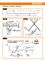
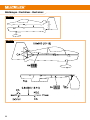
-
 8
8
-
 9
9
-
 10
10
-
 11
11
-
 12
12
-
 13
13
-
 14
14
-
 15
15
-
 16
16
-
 17
17
-
 18
18
-
 19
19
-
 20
20
-
 21
21
-
 22
22
-
 23
23
-
 24
24


MULTIPLEX Slickx360 Bedienungsanleitung
- Typ
- Bedienungsanleitung
- Dieses Handbuch ist auch geeignet für
in anderen Sprachen
- English: MULTIPLEX Slickx360 Owner's manual
- français: MULTIPLEX Slickx360 Le manuel du propriétaire
Verwandte Papiere
-
MULTIPLEX Bk Funnystar Bedienungsanleitung
-
-
MULTIPLEX Funracer Bedienungsanleitung
-
-
-
-
-
-
-


