
DEUTSCH DEUTSCHDEUTSCH DEUTSCH
SICK Encoder sind nach den anerkannten Regeln der Technik herge-
stellte Messgeräte.
▸
Der Anbau des Encoders ist von einem Fachmann mit Kenntnissen
in Elektrik und Feinmechanik vorzunehmen.
▸
Der Encoder darf nur zu dem seiner Bauart entsprechenden Zweck
verwendet werden.
Sicherheitshinweise
▸
Beachten Sie die für Ihr Land gültigen berufsgenossenschaftlichen
Sicherheits- und Unfallverhütungsvorschriften.
▸
Schalten Sie die Spannung bei allen von der Montage betroffenen
Geräte / Maschinen und Anlagen ab.
▸
Elektrische Verbindungen zum Encoder nie bei eingeschalteter Span-
nung herstellen bzw. lösen, dies kann zu Gerätedefekt führen.
▸
Schläge und Stöße auf die Encoderwelle vermeiden, können zu
Kugellagerdefekt führen.
▸
Leitungen mit Zugentlastung versehen, Encoder kann sonst beschä-
digt werden.
▸
Laufweg des Encoders freihalten. Kollisionen mit Objekten können
den Encoder zerstören.
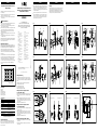
Diese Montageanleitung beschreibt die Montage des Messradsystems.
Bitte beachten Sie auch die Montageanleitung des verwendeten Enco-
ders. Diese liegt dem Encoder bei.
Modulares Messradsystem
Das Messradsystem ist ausgelegt für Federwege bis maximal 7 mm.
Die Vorspannung muss von diesem Wert abgezogen werden. Bei Über-
schreitung des Federwegs kann es zu einer plastischen Verformung
der Feder und langfristig sogar zum Bruch der Feder kommen.
Für die zuverlässige Funktion des Systems ist eine Vorspannung
erforderlich, die einen ausreichenden Anpressdruck auf die Messober-
äche erzeugt.
Daher sollte der Federarm mit einer denierten Vorspannung zwischen
2 und 4 mm montiert werden. Bei einer Messung von unten muss die
Gewichtskraft des Messradsystems bei der Auslegung der Vorspan-
nung und des Federwegs berücksichtigt werden und daher auf 3 -
5 mm erhöht werden. Es steht daher weniger Federweg zur Verfügung.
Die resultierende Anpresskraft ist aus dem Kraft-Weg Diagramm
ersichtlich.
2
(0.08)
4
(0.16)
6
(0.24)
8
(0.31)
10
(0.39)
30
20
0
10
Kraft in N
Weg in mm (inch)
mm
(inch)
Lieferumfang
▸
Federarm
▸
Messrad
▸
Montageschrauben
▸
Fächerscheibe (M6)
▸
Kontermutter (M6)
▸
Distanzring (optional)
Technische Daten
Messrad
Messraddurchmesser 63,66 mm
Messradumfang 200 mm
Material Messrad Aluminium
Material O-Ring EPDM 70
Federarm
Federarm
Zur Einstellung der Anpresskraft
(Vorspannung) sowie zum Ausgleich
von Unebenheiten
Anpresskraft (Vorspannung) max. 31 N, gemessen bei ca. 22 °C
Maximale Auslenkung 7 mm bei 31 N Federkraft
1)
1)
Hinweis:
Bei Überschreitung der maximalen Auslenkung kann es zu
einer plastischen Verformung der Federung und damit zu
einer
Änderung der Federkraft kommen.
Allgemeine Vorbereitung
Beachten Sie bei der Planung der Montage die Maßzeichnungen
(Bilder 3, 4, 7, 8). Achten Sie darauf, dass bei der Ausrichtung der
Encoder-Anschlüsse 3 verschiedene Positionen (jeweils um 120°
versetzt) möglich sind.
Montagevorbereitung
Im Kundensystem eine Bohrung mit Durchmesser 6,2 mm an der
vorgesehenen Position einbringen. Arretierungsbolzen für Langloch
(2,5 mm lang, 4 mm Durchmesser) anbringen (siehe Maßzeichnung
Bild 12).
Zur Montage benötigen Sie folgendes Werkzeug und Zubehör:
▸
Innensechskantschlüssel SW5
▸
Innensechskantschlüssel SW2
▸
Innensechskantschlüssel SW2,5
▸
Gabelschlüssel / Ringschlüssel SW10
Montage am Encoder vom Typ S4, Vollwelle
10 x 19 mm (Bild 1 - Bild 4)
▸
Bei Encodern vom Typ S4 Distanzring (6) auf Encoder (1) aufsetzen.
▸
Federarm (2) in gewünschter Position mit Montageschrauben (3)
festziehen.
▸
Messrad (4) bündig auf Encoderwelle aufsetzen. Es ist darauf zu
achten, dass die Madenschraube des Messrades im Bereich der
Abflachung der Encoderwelle festgezogen wird. Auf freien Lauf am
Federarm achten.
▸
Madenschraube am Messrad festziehen.
Montage am Encoder vom Typ S5, Vollwelle
8 x 15,5 mm (Bild 5 - Bild 8)
▸
Federarm (2) in gewünschter Position mit Montageschrauben (3) am
Encoder (1) festziehen.
▸
Messrad (4) bündig auf Encoderwelle aufsetzen. Es ist darauf zu
achten, dass die Madenschraube des Messrades im Bereich der
Abflachung der Encoderwelle festgezogen wird. Auf freien Lauf am
Federarm achten.
▸
Madenschraube am Messrad festziehen.
Montage am Kundensystem (Bild 9 - Bild 11)
▸
Montageschraube (5) des Messradsystems in kundenseitige Boh-
rung einsetzen.
▸
Fächerscheibe M6 aufsetzen und Mutter M6 lose anschrauben,
nicht festziehen.
SICK Messradsystem für Klemmanschencoder
Montageanleitung
SICK Messradsystem für Klemmanschencoder
mechanisches Design S4 (Vollwelle 10 x 19 mm)
und S5 (Vollwelle 8 x 15,5 mm)
BEF-MRS
SICK STEGMANN GmbH
Postfach 1560 · D-78156 Donaueschingen
Dürrheimer Straße 36 · D-78166 Donaueschingen
Telefon: +49 771 80 70 · Telefax +49 771 80 71 00
www.sick.com · [email protected]
Irrtümer und Änderungen vorbehalten.
Australia
Phone +61 3 9457 0600
Belgium/Luxembourg
Phone +32 (0)2 466 55 66
Brasil
Phone +55 11 3215-4900
Canada
Phone +1 905 771 14 44
Česká republika
Phone +420 2 57 91 18 50
China
Phone +86 4000 121 000
+852-2153 6300
Danmark
Phone +45 45 82 64 00
Deutschland
Phone +49 211 5301-301
España
Phone +34 93 480 31 00
France
Phone +33 1 64 62 35 00
Great Britain
Phone +44 (0)1727 831121
India
Phone +91–22–4033 8333
Israel
Phone +972-4-6801000
Italia
Phone +39 02 27 43 41
Japan
Phone +81 (0)3 3358 1341
Magyarország
Phone +36 1 371 2680
Nederland
Phone +31 (0)30 229 25 44
Österreich
Phone +43 (0)22 36 62 28 8-0
Norge
Phone +47 67 81 50 00
Polska
Phone +48 22 837 40 50
România
Phone +40 356 171 120
Russia
Phone +7-495-775-05-30
Schweiz
Phone +41 41 619 29 39
Singapore
Phone +65 6744 3732
Slovenija
Phone +386 (0)1-47 69 990
South Africa
Phone +27 11 472 3733
South Korea
Phone +82 2 786 6321/4
Suomi
Phone +358-9-25 15 800
Sverige
Phone +46 10 110 10 00
Taiwan
Phone +886-2-2375-6288
Türkiye
Phone +90 (216) 528 50 00
United Arab Emirates
Phone +971 (0) 4 8865 878
USA/México
Phone +1(952) 941-6780
BZ int41
Please find detailed addresses and additional representatives and agencies in
all major industrial nations at www.sick.com
SICK AG, Erwin-Sick-Strasse 1, D-79183 Waldkirch
8016848 / 2013-11-06 ∙ CV
▸
System in gewünschte Position drehen, Vorspannung zur Referenz-
ebene einstellen. Bei aufliegender Montage wird eine Vorspannung
von 2 bis 4 mm empfohlen, bei hängender Montage 3 bis 5 mm.
Die Vorspannung ist dabei abhängig von der Oberflächenbeschaffen-
heit der Lauffläche (Bild 9).
▸
Federarm in der gewünschten Position fixieren. Mutter festdrehen,
dabei die Montageschraube mit einem Innensechskantschlüssel
SW5 fixieren. Nicht am Innensechskantschlüssel drehen, sondern
nur kontern. Über die Mutter festschrauben. Dabei darauf achten,
dass die Vorspannung nicht erhöht wird.
Bild 1
556
1234
Montage Messradsystem für Encoder Typ S4, encoderseitig
Bild 5
1234
5
Montage Messradsystem für Encoder Typ S5, encoderseitig
Bild 9
3–5 mm
3–5°
2–4 mm
2–4°
Vorspannung abhängig von Montageposition.
DEUTSCH
Wartung
Der O-Ring des Messrades (4) ist ein Verschleißteil. Der Verschleiß
hängt von Anpressdruck, Beschleunigung, gesamtem Fahrweg,
Verfahrgeschwindigkeit und Messoberäche ab. Es wird empfohlen
die Beschaffenheit des O-Rings regelmäßig zu prüfen und ihn, wenn
notwendig, auszutauschen (Ersatzteilnummer: 2070901).
Bild 2
5
1
6
234
Montage Messradsystem für Encoder Typ S4, radseitig
Bild 6
5
1234
Montage Messradsystem für Encoder Typ S5, radseitig
Bild 10
Montageposition links Montageposition rechts
Montagepositionen Encoder Typ S5
Bild 3
6
Ø 33
4,05
+0,05
8
63,5
112 ± 2
Ø 63,66
Ø 20
Ø 10
M6
SW 10
DIN912 M6 x 25
17,2 13,8
DIN934 M6
6
10 10
29
siehe Encoder
Abmessung
13
Abmessungen Messradsystem für Encoder Typ S4, encoderseitig
Bild 7
siehe Encoder
Abmessung
6
Ø 33
4,05
+0,05
8
63,5
112 ± 2
Ø 63,66
Ø 20
Ø 10
M6
SW 10
DIN912 M6 x 25
17,2 13,8
DIN934 M6
6
10
20
10
13
Abmessungen Messradsystem für Encoder Typ S5, encoderseitig
Bild 11
Montageposition linksMontageposition rechts
Montagepositionen Encoder Typ S4
Bild 4
siehe Encoder
Abmessung
6
Ø 33
4,05
+0,05
8
63,5
112 ± 2
Ø 63,66
Ø 20
Ø 10
M6
SW 10
DIN912 M6 x 25
17,2
13,8
DIN934 M6
6
10
29
10
12
Abmessungen Messradsystem für Encoder Typ S4, radseitig
Bild 8
siehe Encoder
Abmessung
6
Ø 33
4,05
+0,05
8
63,5
112 ± 2
Ø 63.66
Ø 20
Ø 10
M6
SW 10
DIN912 M6 x 25
17,2
13,8
DIN934 M6
6
10
29
10
12
Abmessungen Messradsystem für Encoder Typ S5, radseitig
Bild 12
6
Ø 33
4,05
+0,05
8
Zeichenschablone für Federarmbefestigung mit Langloch für Vorspan-
nung (Maßstab 1:1).

ENGLISH ENGLISHENGLISH ENGLISH
SICK encoders are measuring devices manufactured using state-of-
the-art technology.
▸
The encoders should only be mounted by a specialist with electrical
and precision engineering knowledge.
▸
The encoder may only be used for the purpose for which it was
intended.
Safety notes
▸
Observe the relevant national work safety regulations as specified by
trade associations.
▸
During mounting, disconnect all applicable devices/machinery and
systems from the voltage.
▸
Never connect or disconnect electrical connections to or from the
encoder when the voltage is switched on, as this may result in equip-
ment damage.
▸
Make sure to avoid any blows or impact to the encoder shaft to
prevent damage to the ball bearings.
▸
Provide cables with strain relief, otherwise the encoder can become
damaged.
▸
Keep the path of the encoder clear. Collisions with objects can
destroy the encoder.
These mounting instructions describe how to mount the measuring
wheel system. Please also observe the mounting instructions of the
encoder being used. These are included with the encoder.
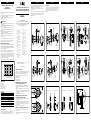
Modular measuring wheel system
The measuring wheel system is designed for spring travel up to max.
7 mm. The pretension must be deducted from this value. Exceeding
the spring travel can lead to plastic deformation of the spring and can
even break the spring long-term.
For reliable operation of the system, pretension is required that gener-
ates adequate contact pressure on the measurement surface.
Therefore, the spring arm should be mounted with a dened pretension
between 2 and 4 mm. For measurement from below, the weight of the
measuring wheel system must be taken into account when designing
the pretension and spring travel, and increased to 3 - 5 mm as a result.
Less spring travel is therefore available.
The resulting contact force is as shown in the force/distance diagram.
2
(0.08)
4
(0.16)
6
(0.24)
8
(0.31)
10
(0.39)
30
20
0
10
Force in N
Distance in mm (inch)
mm
(inch)
Scope of delivery
▸
Spring arm
▸
Measuring wheel
▸
Fitting bolts
▸
Serrated lock washer (M6)
▸
Counter nut (M6)
▸
Spacer ring (optional)
Technical data
Measuring wheel
Measuring wheel diameter 63.66 mm
Measuring wheel circumference 200 mm
Measuring wheel material Aluminum
O-ring material EPDM 70
Spring arm
Spring arm For adjusting the contact force (preten-
sion) and compensating unevenness
Contact force (pretension) 31 N max., measured at approx. 22 °C
Maximum deection 7 mm at a spring force of 31 N
1)
1)
Note:
Exceeding the maximum deection can lead to
plastic
deformation of the spring and hence to a
change in the spring
force.
General preparation
Observe the dimensional drawings (Fig. 3, 4, 7, 8) when planning to
mount the system. Make sure that 3 different positions (each offset by
120°) are possible when aligning the encoder connections.
Preparation for mounting
In the customer system, make a drill hole of 6.2 mm in diameter at the
specied position. Insert the locking bolt for the oblong hole (2.5 mm
long, 4 mm in diameter) (see dimensional drawing, Fig. 12).
The following tools and accessories are required for mounting:
▸
SW5 Allen wrench
▸
SW2 Allen wrench
▸
SW2.5 Allen wrench
▸
SW10 flat/ring spanner
Mounting the system on an S4 type encoder,
10 x 19 mm solid shaft (Fig. 1 - Fig. 4)
▸
With S4 type encoders, place the spacer ring (6) on the encoder (1).
▸
Use fitting bolts (3) to tighten the spring arm (2) in the required
position.
▸
Position the measuring wheel (4) so that it is flush with the encoder
shaft. Make sure that the measuring wheel setscrew in the flat sec-
tion of the encoder shaft is tightened. Check that it can move freely
on the spring arm.
▸
Tighten the setscrew on the measuring wheel.
Mounting the system on an S5 type encoder,
8 x 15.5 mm solid shaft (Fig. 5 - Fig. 8)
▸
Use fitting bolts (3) to tighten the spring arm (2) in the required posi-
tion on the encoder (1).
▸
Position the measuring wheel (4) so that it is flush with the encoder
shaft. Make sure that the measuring wheel setscrew in the flat sec-
tion of the encoder shaft is tightened. Check that it can move freely
on the spring arm.
▸
Tighten the setscrew on the measuring wheel.
Mounting on the customer system (Fig. 9 - Fig. 11)
▸
Insert the fitting bolt (5) of the measuring wheel system in the
customer-side hole.
▸
Loosely position the M6 serrated lock washer and fit the M6 nut, do
not tighten them.
SICK measuring wheel system for face mount
ange encoder
Mounting instructions
SICK measuring wheel system for face mount
ange encoder – S4 (10 x 19 mm solid shaft) and
S5 (8 x 15.5
mm solid shaft) mechanical design
BEF-MRS
SICK STEGMANN GmbH
PO Box 1560 · D-78156 Donaueschingen, Germany
Dürrheimer Straße 36 · D-78166 Donaueschingen, Germany
Phone: +49 771 80 70 · Fax +49 771 80 71 00
www.sick.com · [email protected]
Subject to change without notice.
Australia
Phone +61 3 9457 0600
Belgium/Luxembourg
Phone +32 (0)2 466 55 66
Brasil
Phone +55 11 3215-4900
Canada
Phone +1 905 771 14 44
Česká republika
Phone +420 2 57 91 18 50
China
Phone +86 4000 121 000
+852-2153 6300
Danmark
Phone +45 45 82 64 00
Deutschland
Phone +49 211 5301-301
España
Phone +34 93 480 31 00
France
Phone +33 1 64 62 35 00
Great Britain
Phone +44 (0)1727 831121
India
Phone +91–22–4033 8333
Israel
Phone +972-4-6801000
Italia
Phone +39 02 27 43 41
Japan
Phone +81 (0)3 3358 1341
Magyarország
Phone +36 1 371 2680
Nederland
Phone +31 (0)30 229 25 44
Österreich
Phone +43 (0)22 36 62 28 8-0
Norge
Phone +47 67 81 50 00
Polska
Phone +48 22 837 40 50
România
Phone +40 356 171 120
Russia
Phone +7-495-775-05-30
Schweiz
Phone +41 41 619 29 39
Singapore
Phone +65 6744 3732
Slovenija
Phone +386 (0)1-47 69 990
South Africa
Phone +27 11 472 3733
South Korea
Phone +82 2 786 6321/4
Suomi
Phone +358-9-25 15 800
Sverige
Phone +46 10 110 10 00
Taiwan
Phone +886-2-2375-6288
Türkiye
Phone +90 (216) 528 50 00
United Arab Emirates
Phone +971 (0) 4 8865 878
USA/México
Phone +1(952) 941-6780
BZ int41
Please find detailed addresses and additional representatives and agencies in
all major industrial nations at www.sick.com
SICK AG, Erwin-Sick-Strasse 1, D-79183 Waldkirch, Germany
▸
Turn the system to the required position, adjust the pretension to the
reference plane. We recommend a pretension of 2 to 4 mm when
surface-mounted or 3 to 5 mm when suspended.
The pretension depends on the surface condition of the running
surface (Fig. 9).
▸
Fix the spring arm in the required position. Tighten the nut and fix the
fitting bolt using an SW5 Allen wrench. Do not turn the Allen wrench,
only counter. Screw down the nut. Make sure that the pretension
does not increase.
Fig. 1
556
1234
Mounting of measuring wheel system for S4 type encoder, encoder side
Fig. 5
1234
5
Mounting of measuring wheel system for S5 type encoder, encoder side
Fig. 9
3–5°
2–4°
2–4 mm
(0.08–0.16)
3–5 mm
(0.12–0.20)
Pretension dependent on mounting position
ENGLISH
Maintenance
The O-ring of the measuring wheel (4) is a wearing part. Wear depends
on contact pressure, acceleration, total travel, speed of travel, and
measurement surface. We recommend you regularly check the
condition of the O-ring and replace it as required (spare part number:
2070901).
Fig. 2
5
1
6
234
Mounting of measuring wheel system for S4 type encoder, wheel side
Fig. 6
5
1234
Mounting of measuring wheel system for S5 type encoder, wheel side
Fig. 10
Mounting positions left Mounting positions right
Mounting positions for S5 type encoder
Fig. 3
see Encoder
Dimensions
6 (0.24)
Ø 33
(1.30)
4.05
+0.05
(0.16)
8 (0.31)
63.5 (2.5)
112 ± 2 (4.41)
Ø 63.66 (2.51)
Ø 20
(0.79)
Ø 10
(0.39)
M6
SW 10
DIN912 M6 x 25
17.2
(0.68)
13.8
(0.54)
DIN934 M6
6 (0.24)
10
(0.39)
29
(1.14)
10
(0.39)
13
(0.52)
Dimensions of measuring wheel system for S4 type encoder, encoder side
Fig. 7
see Encoder
Dimensions
6 (0.24)
Ø 33
(1.30)
4.05
+0.05
(0.16)
8 (0.31)
63.5 (2.5)
112 ± 2 (4.41)
Ø 63.66 (2.51)
Ø 20
(0.79)
Ø 10
(0.39)
M6
SW 10
DIN912 M6 x 25
17.2
(0.68)
13.8
(0.54)
DIN934 M6
6 (0.24)
10
(0.39)
20
(0.79)
10
(0.39)
13
(0.52)
Dimensions of measuring wheel system for S5 type encoder, encoder side
Fig. 11
Mounting positions leftMounting positions right
Mounting positions for S4 type encoder
Fig. 4
see Encoder
Dimensions
6 (0.24)
Ø 33
(1.30)
4.05
+0.05
(0.16)
8 (0.31)
63.5 (2.5)
112 ± 2 (4.41)
Ø 63.66 (2.51)
Ø 20
(0.79)
Ø 10
(0.39)
M6
SW 10
DIN912 M6 x 25
17.2
(0.68)
13.8
(0.54)
DIN934 M6
6 (0.24)
10
(0.39)
10
(0.39)
12
(0.47)
29
(1.14)
Dimensions of measuring wheel system for S4 type encoder, wheel side
Fig. 8
see Encoder
Dimensions
6 (0.24)
Ø 33
(1.30)
4.05
+0.05
(0.16)
8 (0.31)
63.5 (2.5)
112 ± 2 (4.41)
Ø 63.66 (2.51)
Ø 20
(0.79)
Ø 10
(0.39)
M6
SW 10
DIN912 M6 x 25
17.2
(0.68)
13.8
(0.54)
DIN934 M6
6 (0.24)
10
(0.39)
10
(0.39)
12
(0.47)
29
(1.14)
Dimensions of measuring wheel system for S5 type encoder, wheel side
Fig. 12
6 (0.24)
Ø 33 (1.30)
4.05
+0.05
(0.16)
8 (0.31)
Template for mounting the spring arm with oblong hole for pretension
(scale 1:1)
8016848 / 2013-11-06 ∙ CV
-
 1
1
-
 2
2


in anderen Sprachen
- English: SICK BEF-MRS
Verwandte Artikel
-
SICK DBV50 Core Measuring wheel encoders Bedienungsanleitung
-
-
-
-
-
-
-
-
-
