SICK DFV60 Measuring wheel encoder Bedienungsanleitung
- Typ
- Bedienungsanleitung

DEUTSCH
SICK-Encoder sind nach den anerkannten Regeln der Technik herge-
stellte Messgeräte.
a
Der Anbau des Encoders ist von einem Fachmann mit Kenntnissen
in Elektrik und Feinmechanik vorzunehmen.
a
Der Encoder darf nur zu dem seiner Bauart entsprechenden Zweck
verwendet werden.
Sicherheitshinweise
▸
Beachten Sie die für Ihr Land gültigen berufsgenossenschaftlichen
Sicherheits- und Unfallverhütungsvorschriften.
▸
Schalten Sie die Spannung bei allen von der Montage betroffenen
Geräten/Maschinen und Anlagen ab.
▸
Elektrische Verbindungen zum Encoder nie bei eingeschalteter
Spannung herstellen bzw. lösen, kann sonst zu einem Gerätedefekt
führen.
▸
Schläge und Stöße auf die Encoderwelle unbedingt vermeiden, kann
zu Kugellagerdefekt führen.
▸
Für eine einwandfreie Funktion der Encoder ist auf eine EMV gerech-
te Schirmverbindung (beidseitiges Auflegen des Schirms) zu achten!
Allgemein gültige Hinweise
Bei Encodern mit Kabelabgang ist das Schirmgeecht mit dem
Gehäuse verbunden. Es ist unter EMV-Gesichtspunkten zwingend
notwendig, dass das Gehäuse bzw. der Kabelschirm an Erde bzw.
Masse angeschlossen wird. Dies wird durch den Anschluss des
Kabel-Schirmgeechts realisiert. Das Schirmgeecht sollte großächig
angeschlossen werden.
Anschlussbelegung
Ansicht Gerätestecker M12 am Encoder.
PIN, 8-pol.,
M12-Stecker
Farbe der
Adern
Signal
TTL, HTL
Erklärung
1 Braun ‾A Signalleitung
2 Weiß A Signalleitung
3 Schwarz ‾B Signalleitung
4 Rosa B Signalleitung
5 Gelb ‾Z Signalleitung
6 Violett Z Signalleitung
7 Blau GND
Masseanschluss des
Encoders
8 Rot +U
S
Versorgungsspannung
(potenzialfrei zum
Gehäuse)
Schirm Schirm Schirm
Schirm Encoderseitig
mit Gehäuse verbun-
den. Steuerungsseitig
mit Erde verbinden.
a
ACHTUNG!
PIN-Belegung nur für Standard-Encoder gültig. Bei kundenspezifi-
schen Encodern bitte entsprechendes Datenblatt verwenden.
Um eine gute Signalqualität zu erhalten empfehlen wir grundsätzlich,
die Encodersignale dierentiell auszuwerten.
Nicht verwendete Encoderadern/Signale bitte dierentiell abschlie-
ßen, d. h. zwischen dem Signal und dem Komplementärsignal ist ein
Abschlusswiderstand einzufügen, der so zu dimensionieren ist, dass
ein Strom von 12,5 mA ± 20 % ießt.
Bei Encodern mit Steckeranschluss sollten nicht verwendete Signale
nicht weitergeführt werden.
DEUTSCHDEUTSCH
Montage DFV60
Montage DFV60 Messrad-Encoder und DFV60
Federarm (Bild 1 und Bild 2)
▸
Entfernen der 2 Splinte (1) vom DFV60 Federarm.
▸
Montage des DFV60 Encoders und DFV60 Federarmes durch das
Einfügen der 2 Bolzen (2) in die Bohrungen (3).
▸
Befestigung der 2 Bolzen (2) mittels der Splinte (1).
▸
Der komplett montierte Messrad-Encoder ist in Bild 2 dargestellt.
Montage DFV60 Messrad-Encoder am Förderband
(Bild 3)
▸
Montage des DFV60 Messrad Encoder (1) fluchtend zur Bewegungs-
richtung des Förderbandes (2).
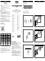
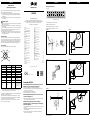
DFV60 Messrad-Encoder, Einbauraum (Bild 4),
Vorspannung (Bild 5) und Federweg (Bild 6)
▸
Für eine optimale und fehlerfreie Funktion ist ein Einbauraum von
mind. 200 mm erforderlich (Bild 4).
▸
Für eine optimale und fehlerfreie Funktion wird einer Vorspannung
des Federarms von 20 mm empfohlen (Bild 5).
▸
Der maximale Federwege des Federarms beträgt 40 mm (Bild 6).
Federvorspannung
5
(0.20)
10
(0.39)
15
(0.59)
20
(0.79)
25
(0.98)
20
0
10
Kraft in N
30
(1.18)
35
(1.38)
40
(1.57)
45
(1.77)
Weg in mm (inch)
mm
(inch)
1
4
2
3
1 Empfohlene Vorspannung (20 mm)
2 Maximale zulässige Auslenkung (40 mm)
3 Empfohlener Auslenkungsbereich (10 – 30 mm)
4 Zulässiger Arbeitsbereich (0 – 30 mm)
Bild 1
1
2
2
3
Montage DFV60 Messrad-Encoder und DFV60 Federarm
Bild 2
DFV60 Messrad-Encoder komplett montiert
Bild 3
2
1
DFV60 Messrad Encoder uchtend montiert zur Bewegungsrichtung
des Förderbandes
Bild 4
200 mm
Erforderlicher Einbauraum
Bild 5
180 mm (20 mm)
Optimale Vorspannung des DFV60 Messrad Encoders am Förderband
Bild 6
40 mm
Maximaler Federweg DFV60 Messrad-Encoder
SICK Encoder
Betriebsanleitung
SICK Encoder
DFV60
SICK STEGMANN GmbH
Postfach 1560 · D-78156 Donaueschingen
Dürrheimer Straße 36 · D-78166 Donaueschingen
Telefon: +49 (0) 771 80 70 · Telefax +49 (0) 771 80 71 00
www.sick.com · [email protected]
Irrtümer und Änderungen vorbehalten.
8013709/141R/2019-05-21 · AB_07
Australia
Phone +61 (3) 9457 0600
Austria
Phone +43 (0) 2236 62288-0
Belgium/Luxembourg
Phone +32 (0) 2 466 55 66
Brazil
Phone +55 11 3215-4900
Canada
Phone +1 905.771.1444
Czech Republic
Phone +420 2 57 91 18 50
Chile
Phone +56 (2) 2274 7430
China
Phone +86 20 2882 3600
Denmark
Phone +45 45 82 64 00
Finland
Phone +358-9-25 15 800
France
Phone +33 1 64 62 35 00
Germany
Phone +49 (0) 2 11 53 01
Hong Kong
Phone +852 2153 6300
Hungary
Phone +36 1 371 2680
India
Phone +91-22-6119 8900
Israel
Phone +972-4-6881000
Italy
Phone +39 02 27 43 41
Japan
Phone +81 3 5309 2112
Malaysia
Phone +603-8080 7425
Mexico
Phone +52 (472) 748 9451
Netherlands
Phone +31 (0) 30 229 25 44
New Zealand
Phone +64 9 415 0459
Norway
Phone +47 67 81 50 00
Poland
Phone +48 22 539 41 00
Romania
Phone +40 356-17 11 20
Russia
Phone +7 495 283 09 90
Singapore
Phone +65 6744 3732
Slovakia
Phone +421 482 901 201
Slovenia
Phone +386 591 78849
South Africa
Phone +27 (0)11 472 3733
South Korea
Phone +82 2 786 6321
Spain
Phone +34 93 480 31 00
Sweden
Phone +46 10 110 10 00
Switzerland
Phone +41 41 619 29 39
Taiwan
Phone +886-2-2375-6288
Thailand
Phone +66 2 645 0009
Turkey
Phone +90 (216) 528 50 00
United Arab Emirates
Phone +971 (0) 4 88 65 878
United Kingdom
Phone +44 (0)17278 31121
USA
Phone +1 800.325.7425
Vietnam
Phone +65 6744 3732
BZ int48
Nur für Anschlussart Stecker.

ENGLISH
SICK encoders are measuring instruments produced in accordance
with recognized industrial regulations.
a
The installation of the encoder is to be carried out by trained
personal with knowledge of electrical engineering and precision
engineering.
a
A DFV60 encoder must be used only for the purpose appropriate
to its design.
Safety advice
▸
Observe the professional safety and accident prevention regulations
applicable to your country.
▸
Switch of the voltage to all the devices/machines and plant involved
in the mounting.
▸
Never electrically connect or disconnect the encoder with the voltage
switched on, otherwise this may lead to damage to the encoder.
▸
Avoid striking the shaft of the encoder.
▸
For the satisfactory operation of the devices, care must be paid to
good earthing and to a screen connection suitable for EMC (screen
connected at both ends).
General advice
In case of the encoders with cable outlet, the screening braid is con-
nected to the housing. From the point of view of EMC, it is absolutely
necessary for the housing or cable screen to be connected to earth
or ground. This can be done by connecting the screening braid of the
cable. The screening braid should be connected over a large area.
Pin allocation
View to the connector M12 tted to the encoder body.
PIN, 8-pin,
M12 connector
Color of wires Signal
TTL, HTL
Explanation
1 Brown ‾A Signal line
2 White A Signal line
3 Black ‾B Signal line
4 Pink B Signal line
5 Yellow ‾Z Signal line
6 Lilac Z Signal line
7 Blue GND
Ground connection of
the encoder
8 Red +U
S
Supply voltage (poten-
tial free to housing)
Screen Screen Screen
Screen on the encoder
side connected to the
housing. On the control
side connected to
earth.
a
Attention!
PIN allocation only valid for standard encoder. For customer spe-
cific versions please see the relevant data sheet.
In order to achieve a high signal quality, we recommend a dierential
evaluation of the encoder signals.
Unused signal wires shall be connected dierentially, i.e. a resistor
needs to be connected between signal wire and inverted signal wire.
The resulting current should be 12.5 mA ± 20 %.
For encoders with connector, the unused signals must not be con-
nected to the customer cabling.
ENGLISHENGLISH
Assembly DFV60
Assembling DFV60 measuring wheel encoder and
DFV60 spring arm (Figure 1 and Figure 2)
▸
Remove the 2 R-clips (1) from the DFV60 spring arm.
▸
Assemble the DFV60 encoder to the DFV60 spring arm using the
2 bolts (2) into the 2 bores (3).
▸
Fix the 2 bolts (2) with the 2 R-clips (1).
▸
The assembled device is shown in figure 2.
Mounting DFV60 measuring wheel encoder on the
conveyor belt (Figure 3)
▸
Mount the DFV60 measuring wheel encoder (1) align with the direc-
tion of motion of the conveyor belt (2).
DFV60 measuring wheel encoder, mounting
dimension (Figure 4), preload (Figure 5) and spring
deection (Figure 6)
▸
For reliable operation a mounting dimension of 200 mm is necessary
(figure 4).
▸
For reliable operation a preload equivalent to 20 mm is recom-
mended (figure 5).
▸
The maximum spring deflection of the DFV60 measuring wheel
encoder is 40 mm (figure 6).
Spring pretensioning
5
(0.20)
10
(0.39)
15
(0.59)
20
(0.79)
25
(0.98)
20
0
10
Force in N
30
(1.18)
35
(1.38)
40
(1.57)
45
(1.77)
Deflection in mm (inch)
mm
(inch)
1
4
2
3
1 Recommended pre-tension (20 mm)
2 Maximum deection (40 mm)
3 Recommended deection (10 – 30 mm)
4 Permissible working range (0 – 30 mm)
Figure 1
1
2
2
3
Assembling DFV60 measuring wheel encoder and DFV60 spring arm
Figure 2
Final assembling DFV60 encoder and DFV60 spring arm
Figure 3
2
1
DFV60 measuring wheel encoder assembled align with the conveyor
belt motion direction
Figure 4
200 mm
(7.87 inch)
Required mounting dimension
Figure 5
180 mm (20 mm)
(7.09 inch (0.79 inch))
Optimal preload equivalent of the DFV60 at the conveyor belt
Figure 6
40 mm
(1.57 inch)
Maximum spring deection of the DFV60 measuring wheel encoder
SICK Encoders
Operating instructions
SICK Encoders
DFV60
SICK STEGMANN GmbH
PO Box 1560 · D-78156 Donaueschingen, Germany
Dürrheimer Straße 36 · D-78166 Donaueschingen, Germany
Phone: +49 771 80 70 · Fax: +49 771 80 71 00
www.sick.com · [email protected]
Subject to change without notice.
8013709/141R/2019-05-21 · AB_07
Australia
Phone +61 (3) 9457 0600
Austria
Phone +43 (0) 2236 62288-0
Belgium/Luxembourg
Phone +32 (0) 2 466 55 66
Brazil
Phone +55 11 3215-4900
Canada
Phone +1 905.771.1444
Czech Republic
Phone +420 2 57 91 18 50
Chile
Phone +56 (2) 2274 7430
China
Phone +86 20 2882 3600
Denmark
Phone +45 45 82 64 00
Finland
Phone +358-9-25 15 800
France
Phone +33 1 64 62 35 00
Germany
Phone +49 (0) 2 11 53 01
Hong Kong
Phone +852 2153 6300
Hungary
Phone +36 1 371 2680
India
Phone +91-22-6119 8900
Israel
Phone +972-4-6881000
Italy
Phone +39 02 27 43 41
Japan
Phone +81 3 5309 2112
Malaysia
Phone +603-8080 7425
Mexico
Phone +52 (472) 748 9451
Netherlands
Phone +31 (0) 30 229 25 44
New Zealand
Phone +64 9 415 0459
Norway
Phone +47 67 81 50 00
Poland
Phone +48 22 539 41 00
Romania
Phone +40 356-17 11 20
Russia
Phone +7 495 283 09 90
Singapore
Phone +65 6744 3732
Slovakia
Phone +421 482 901 201
Slovenia
Phone +386 591 78849
South Africa
Phone +27 (0)11 472 3733
South Korea
Phone +82 2 786 6321
Spain
Phone +34 93 480 31 00
Sweden
Phone +46 10 110 10 00
Switzerland
Phone +41 41 619 29 39
Taiwan
Phone +886-2-2375-6288
Thailand
Phone +66 2 645 0009
Turkey
Phone +90 (216) 528 50 00
United Arab Emirates
Phone +971 (0) 4 88 65 878
United Kingdom
Phone +44 (0)17278 31121
USA
Phone +1 800.325.7425
Vietnam
Phone +65 6744 3732
BZ int48
For connection type male connector only.
-
 1
1
-
 2
2


SICK DFV60 Measuring wheel encoder Bedienungsanleitung
- Typ
- Bedienungsanleitung
in anderen Sprachen
Verwandte Artikel
-
SICK PGT-10-Pro Bedienungsanleitung
-
-
-
-
-
-
-
-
-
