SICK DUS60 Incremental encoder Bedienungsanleitung
- Typ
- Bedienungsanleitung

DEUTSCH DEUTSCH DEUTSCH DEUTSCHDEUTSCH DEUTSCHDEUTSCH DEUTSCH
SICK Encoder
Betriebsanleitung
SICK Encoder
DUS60
SICK STEGMANN GmbH
Postfach 1560 · D-78156 Donaueschingen
Dürrheimer Straße 36 · D-78166 Donaueschingen
Telefon: +49 (0) 771 80 70 · Telefax +49 (0) 771 80 71 00
www.sick.com · [email protected]
SICK Encoder sind nach den anerkannten Regeln der Technik hergestellte
Messgeräte.
a Der Anbau des Encoders ist von einem Fachmann mit Kenntnissen in
Elektrik und Feinmechanik vor zunehmen.
a Der Encoder darf nur zu dem seiner Bauart ent sprechenden Zweck
verwendet werden.
Sicherheitshinweise
▸
Beachten Sie die für Ihr Land gültigen berufsgenossenschaftlichen
Sicherheits- und Unfallverhütungsvorschriften.
▸
Schalten Sie die Spannung bei allen von der Montage betroffenen
Geräten / Maschinen und Anlagen ab.
▸
Elektrische Verbindungen zum Encoder nie bei ein geschalteter Spannung
herstellen bzw. lösen, kann sonst zu einem Gerätedefekt führen.
▸
Stöße auf die Encoderwelle unbedingt vermeiden, um eine Beschädi-
gung des Kugellagers auszuschließen.
▸
Für eine einwandfreie Funktion der Encoder ist auf eine EMV gerechte
Schirmverbindung (beidseitiges Auflegen des Schirms) zu achten!
Allgemein gültige Hinweise
Die genaue Zentrierung des Encoders verringert den Winkel- und Wellen-
versatz bei der Montage und senkt die Belastungen für die Drehmoment-
stütze und die Lager des Encoders.
Um die Drehmomentstütze bei der Montage nicht zu verspannen, immer
erst den Encoder ananschen und dann den Klemmring der Hohlwellen-
klemmung befestigen.
Bei Encodern mit Leitungsanschluss ist das Schirmgeecht mit dem
Gehäuse verbunden.
Bitte nicht vorgesehene Drehungen vermeiden, z. B. durch das Fixieren
der Leitung.
Der IP Schutz des Encoders kann nur erreicht werden, wenn die Abdeckung
der DIP-Schalter plan mit dem Gehäuse des Encoders abschließt.
Es ist unter EMV-Gesichtspunkten zwingend notwendig, dass das Gehäuse
oder der Leitungsschirm an Erde oder Masse angeschlossen wird. Dies
wird durch den Anschluss des Leitungs-Schirmgeechts realisiert. Das
Schirmgeecht sollte großächig angeschlossen werden.
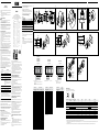
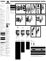
M12-Steckverbinder (Abb. A und Abb. B)
Der M12-Steckverbinder (1) am Encoder kann bis zu 90 Grad zwischen
den axialen und radialen Positionen gedreht werden, um den unterschied-
lichen Einbauumgebungen einer Anwendung noch besser entsprechen zu
können.
Der Stecker der drehbaren Steckereinheit steht in zwei Ausführungen zur
Verfügung.
Zur Anbringung der Leitung gehen Sie wie folgt vor:
▸
Drehbare Steckereinheit mit der Buchse der Leitung verbinden.
▸
Gehäuse der Steckverbindung vorsichtig in die gewünschte Position
drehen.
Die drehbare Steckereinheit ist nur während der Montage und für die
Ausrichtung zur Steckerverbindung in die gewünschte Position zu bringen.
Sie ist nicht für eine kontinuierliche Bewegung gedacht.
Übermäßige Drehungen oder hoher Krafteinsatz können die Steckerdich-
tung beschädigen, was den IP Schutz des Encoders reduzieren würde.
LEDs ! (Abb. A und Abb. C)
Anzeige Beschreibung
Status LED
o Aus
Keine Versorgungsspannung
O Grün
Encoder ist betriebsbereit
O Rot
Encoder ist außer Betrieb
ôOõ Rot / ôOõ Grün
Farbwechsel zwischen rot und grün zeigt
an, dass die Stellung der DIP-Schalter
geändert wurde.
Bleibt der Wechsel auch nach 3 Sekunden
aktiv, ist die Stellung der DIP-Schalter zu
überprüfen.
Signal LED
1) 2)
ôOõ und O Honiggelb
Ausgabe am Kanal A ist aktiv und hoch
o Honiggelb
Ausgabe am Kanal A ist gering
1)
Bitte beachten Sie, dass die Signal LED blinkt, wenn der Encoder
arbeitet. Bei hohen Geschwindigkeiten entsteht kann der Eindruck
entstehen, als würde die LED durchgängig leuchten.
2)
Bei Encodern mit wechselnder Ausgangskonguration (CW oder
CCW) verändert sich die Signal LED je nach anliegender Kongu-
ration.
DIP-Schalter (Abb. A und Abb. D)
Über die DIP-Schalter (4) lassen sich die Impulse pro Umdrehung, die Aus-
gangsspannung und die Zählrichtung bestimmen (siehe DIP-Konguration).
▸
Abdeckung der DIP-Schalter durch Drehen öffnen.
▸
DIP-Schalter gemäß Anwendungszweck einstellen (siehe DIP-Konfigura-
tion).
▸
Abdeckung der DIP-Schalter durch Drehen und Drücken vollständig und
plan schließen. Um den IP Schutz des Encoders zu gewährleisten, muss
der DIP-Schalter plan mit dem Gehäuse des Encoders abschließt.
Montage Hülse (Abb. E)
Torxschraube (1) lösen und ggf. Hülse einsetzen.
Geschlitzte Hülsen so ausrichten, dass die Aussparung sich mit der
Vertiefung der Bohrung (2) für die Torxschraube deckt (nicht notwendig bei
ungeschlitzten Hülsen).
Torxschraube leicht anziehen (Anzugsdrehmoment 0,2 Nm).
Anbau DUS60 Aufsteckhohlwelle mit
Drehmomentstütze (Abb. F)
▸
Kundenseitige Antriebswelle blockieren, um deren Drehung zu verhin-
dern.
▸
Lösen der Innensechskantschraube (1) am Klemmring (2) mit einem
Innensechskantschraubenschlüssel; SW2.
▸
Länge der Welle beachten.
Irrtümer und Änderungen vorbehalten
Nur für NFPA 79 Anwendungen.
BZ int49
Detailed addresses and further locations at www.sick.com
Australia
Phone +61 (3) 9457 0600
1800 33 48 02 –
tollfree
Austria
Phone +43 (0) 2236 62288-0
Belgium/Luxembourg
Phone +32 (0) 2 466 55 66
Brazil
Phone +55 11 3215-4900
Canada
Phone +1 905.771.1444
Czech Republic
Phone +420 234 719 500
Chile
Phone +56 (2) 2274 7430
China
Phone +86 20 2882 3600
Denmark
Phone +45 45 82 64 00
Finland
Phone +358-9-25 15 800
France
Phone +33 1 64 62 35 00
Germany
Phone +49 (0) 2 11 53 010
Greece
Phone +30 210 6825100
Hong Kong
Phone +852 2153 6300
Hungary
Phone +36 1 371 2680
India
Phone +91-22-6119 8900
Israel
Phone +972 97110 11
Italy
Phone +39 02 27 43 41
Japan
Phone +81 3 5309 2112
Malaysia
Phone +603-8080 7425
Mexico
Phone +52 (472) 748 9451
Netherlands
Phone +31 (0) 30 229 25 44
New Zealand
Phone +64 9 415 0459
0800 222 278 – tollfree
Norway
Phone +47 67 81 50 00
Poland
Phone +48 22 539 41 00
Romania
Phone +40 356-17 11 20
Russia
Phone +7 495 283 09 90
Singapore
Phone +65 6744 3732
Slovakia
Phone +421 482 901 201
Slovenia
Phone +386 591 78849
South Africa
Phone +27 10 060 0550
South Korea
Phone +82 2 786 6321/4
Spain
Phone +34 93 480 31 00
Sweden
Phone +46 10 110 10 00
Switzerland
Phone +41 41 619 29 39
Taiwan
Phone +886-2-2375-6288
Thailand
Phone +66 2 645 0009
Turkey
Phone +90 (216) 528 50 00
United Arab Emirates
Phone +971 (0) 4 88 65 878
United Kingdom
Phone +44 (0)17278 31121
USA
Phone +1 800.325.7425
Vietnam
Phone +65 6744 3732
8020044 /13FC / 2019 - 06 - 05 ● LF_07
BA C D
F G
H
min. 15 mm
min. 54 mm
3 x M4 bei 48 mm
Tiefe < 6 mm
3 x M3 bei 48 mm
Tiefe < 6 mm
min. 15 mm
max. 40 mm
43.8
(1.72)
27.6
(1.09)
3.2 +0.1
(0.13)
50 (1.97)
31.41
(1.24)
6.6
(0.26)
11.8
(0.46)
27.9
(1.10)
26
(1.02)
6.6
(0.26)
Ø 25
(0.98)
Ø 58 (2.28)
Ø x F 7
63
(2.48)
83 (3.27)
94 (3.70)
9.4
(0.37)
2
(0.08)
▸
Encoder mit montierter Kupplung (1) auf Antriebswelle und Klemman-
satz in Klemmvorrichtung (2) schieben.
▸
Encoder mit Schraube (3) festklemmen.
▸
Kupplung (1) auf der Antriebswelle befestigen.
▸
Die Kupplung darf keinen mechanischen Spannungen ausgesetzt
werden.
▸
Elektrische Verbindungen bei ausgeschalteter Spannung herstellen.
▸
Spannung einschalten und Funktion des Encoders prüfen.
Drehmomentstütze und Befestigung
Tab. 1
Artikelbezeichnung
Drehmomentstütze
Var. Schrauben
ohne Drehmomentstütze A
4
x M2.5
2-seitig, Langloch, Lochkreis 63 – 83 mm O
2
x M3
2-seitig, Lochkreis 63 mm B
4
x M3
1-seitig, Langloch, Lochkreisradius
33
– 48.5 mm
D
1
x M5
1-seitig, Langloch, Lochkreisradius
32.25
– 142.65 mm
E
1
x M4
1-seitig, Langloch, Lochkreisradius
32.1
– 37.6 mm
G
1
x M4
Bei Modellen ohne Drehmomentstütze (Variante A) ist auf eine ausrei-
chende mechanische Entkopplung zwischen Encoder und Anwendung zu
achten.
Eine nicht ausreichende Entkopplung kann zur mechanischen Beschädi-
gung des Encoders führen.
Wartung
Überprüfen Sie den korrekten Sitz der Abdeckung für die DIP-Schalter
regelmäßig.
Reinigen Sie die LEDs mit einem weichen Tuch. Verwenden Sie das Tuch
entweder trocken oder feuchten Sie es mit lauwarmem Wasser und etwas
mildem Reinigungsmittel an.
▸
Encoder auf die Antriebswelle aufschieben.
▸
Darauf achten, dass die Encoderwelle der Kundenanwendung sich frei
drehen kann.
▸
Drehmomentstütze (4) mit Schrauben (3) (siehe Tab. 1) und U-Scheiben
(5) befestigen. Dabei sicherstellen, dass das Anzugsmoment so gewählt
wird, dass ein Verdrehen des Encoders nicht möglich ist.
▸
Darauf achten, dass die Drehmomentstütze nicht vorgespannt ist.
▸
Innensechskantschraube (1) am Klemmring (2) leicht anziehen (Anzugs-
moment 0,2 Nm), danach festziehen. Anzugsdrehmoment = 1,5 / 1,1 Nm
(Hülse: Metall /Kunststoff)
▸
Elektrische Verbindungen bei abgeschalteter Spannung herstellen.
▸
Spannung einschalten und Funktion des Encoders überprüfen.
Anbau DUS60 Durchsteckhohlwelle mit
Drehmomentstütze (Abb. G und Abb. H)
▸
Kundenseitige Antriebswelle blockieren, um deren Drehung zu verhin-
dern.
▸
Lösen der Innensechskantschraube (1) am Klemmring (2) mit einem
Innensechskantschraubenschlüssel; SW2.
▸
Länge der Welle beachten.
▸
Encoder auf die Antriebswelle aufschieben.
▸
Darauf achten, dass die Encoderwelle der Kundenanwendung sich frei
drehen kann.
▸
Drehmomentstütze (4) mit Schrauben (3) (siehe Tab. 1) und U-Scheiben
(5) befestigen. Dabei sicherstellen, dass das Anzugsmoment so gewählt
wird, dass ein Verdrehen des Encoders nicht möglich ist.
▸
Darauf achten, dass die Drehmomentstütze nicht vorgespannt ist.
▸
Innensechskantschraube (1) am Klemmring (2) leicht anziehen (Anzugs-
moment 0,2 Nm), danach festziehen.Anzugsdrehmoment = 1,5 / 1,1 Nm
(Hülse: Metall /Kunststoff)
▸
Elektrische Verbindungen bei abgeschalteter Spannung herstellen.
▸
Spannung einschalten und Funktion des Encoders überprüfen.
Anbau DUS60 Klemm- bzw. über anschseitige
Gewindebohrungen (Abb. I)
▸
Kundenseitige Antriebswelle blockieren, um deren Drehung zu verhin-
dern.
▸
Kupplung (1) am Encoder montieren; darauf achten, dass diese nicht am
Encoderflansch streift.
▸
Encoder mit montierter Kupplung (1) auf Antriebswelle und Zent-
rier- / Klemmsatz (2) aufschieben.
▸
Encoder so ausrichten, dass das Lochbild in der Anwendung mit dem
entsprechenden Lochbild des Encoders übereinstimmt.
▸
Encoder mit 3 Schrauben M3 bzw. M4 (3) befestigen.
▸
Kupplung (1) auf der Antriebswelle montieren.
▸
Die Kupplung darf keinen mechanischen Spannungen ausgesetzt
werden.
▸
Elektrische Verbindungen bei ausgeschalteter Spannung herstellen.
▸
Spannung einschalten und Funktion des Encoders prüfen.
Anbau DUS60 Klemmansch über den Klemmansatz
(Abb. J)
a ACHTUNG!
Da der Klemmansatz gleichzeitig auch Zentrieransatz ist, muss die
Klemmvorrichtung so ausgebildet sein, dass beim Festklemmen kein
unzulässiger Winkel- bzw. Wellenversatz entsteht.
▸
Kundenseitige Antriebswelle blockieren, um deren Drehung zu verhin-
dern.
▸
Kupplung (1) montieren; darauf achten, dass diese nicht am Encoder-
flansch streift.
I J
E
12345678
ON
Anschlussbelegung
a Die max. Leitungslänge darf 30 m nicht überschreiten.
34
12
58
46
7
1
3
2
M12 Stecker, 4-polig, A-kodiert M12 Stecker, 8-polig, A-kodiert
Farbe der Adern M12-Stecker, 4-polig,
A-kodiert
M12-Stecker, 8-polig,
A-kodiert
Ausgabe
A
Ausgabe
B
Ausgabe
C
Ausgabe
D
Erklärung
Braun - 1 A- CW- A- A- Signalleitung
Weiß 4 2 A CW A A Signalleitung
Schwarz - 3 B- CCW- Richtung- B- Signalleitung
Rosa
2
B CCW Richtung
Störung (4-polig)
Signalleitung
4 B (8-polig)
Gelb - 5 Z- Störung- Störung- Störung- Signalleitung
Lila - 6 Z Störung Störung Störung Signalleitung
Blau 3 7 GND GND GND GND Masseanschluss des Encoders
Rot 1 8 +U
s
+U
s
+U
s
+U
s
Versorgungsspannung
- - - Gehäuse Gehäuse Gehäuse Gehäuse Gehäusemasse
Schirm - - Schirm Schirm Schirm Schirm Schirm (encoderseitig mit Gehäuse verbunden)
a ACHTUNG!
PIN-Belegung nur für Standard-Encoder gültig. Bei kundenspezischen Encodern bitte entsprechendes Datenblatt verwenden.
▸
Um die Qualität des Signals zu gewährleisten, wird empfohlen, die komplementären Ausgangssignale (z A / A-, B / B-, Z / Z) zu überwachen. Verwenden Sie dazu ein abgeschirmtes Twisted-Pair-Kabel mit den komplementären
Signalen, paarweise verdrillt.
▸
Wir empfehlen die Verwendung von Leitungen aus dem SICK Zubehör oder von Leitungen gleichwertiger Qualität. Informationen zum SICK Zubehör können Sie den entsprechenden Datenblättern entnehmen.
DIP Switches 2 - 7 Pulses Per Revolution
Conguration Selection A - 2400 B - 2048 C - 1800 D - 1500
□□□□□■ 1 1 1 1
□□□□■□ 2 2 2 2
□□□□■■ 3 4 3 3
□□□■□□ 4 8 4 4
□□□■□■ 5 16 5 5
□□□■■□ 6 32 6 6
□□□■■■ 8 64 8 10
□□■□□□ 10 128 9 12
□□■□□■ 12 256 10 15
□□■□■□ 15 512 12 20
□□■□■■ 16 1024 15 30
□□■■□□ 20 18 60
□□■■□■ 24 20 75
□□■■■□ 30 24 100
□□■■■■ 32 30 150
□■□□□□ 40 36 300
□■□□□■ 48 40
□■□□■□ 60 60
□■□□■■ 75 72
□■□■□□ 80 75
□■□■□■ 96 100
□■□■■□ 100 120
□■□■■■ 120 150
□■■□□□ 150 180
□■■□□■ 160 200
□■■□■□ 200 300
□■■□■■ 240 360
□■■■□□ 300 450
□■■■□■ 400 600
□■■■■□ 480 900
□■■■■■ 600
■□□□□□ 800
■□□□□■ 1200
□□□□□□ 2400 2048 1800 1500
OFF = □↑ ON = ■↓
DIP Switches 1 - 5 Pulses Per Revolution*
Conguration Selection E - 240 G - 48
□□□□□ 1 1
■□□□□ 2 2
□■□□□ 3 3
■■□□□ 4 4
□□■□□ 5 6
■□■□□ 6 8
□■■□□ 8
■■■□□ 10 12
□□□■□ 12 16
■□□■□ 15
□■□■□ 16 24
■■□■□ 20
□□■■□ 24 48
■□■■□ 30
□■■■□ 40
■■■■□ 48
□□□□■ 60
■□□□■ 80
□■□□■ 120
■■□□■ 240
OFF = □↑ ON = ■↓
*Only clockwise (CW)
DIP Switches 2 - 6 Pulses Per
Revolution
Conguration Selection F - 60
■□□□□ 2
□■□□□ 3
■■□□□ 4
□□■□□ 5
■□■□□ 6
■■■□□ 8
■□□■□ 10
□■□■□ 12
■■□■□ 15
□□□□■ 16
□□■■□ 20
■□■■□ 24
□■■■□ 30
□□□□□ 60
OFF = □↑ ON = ■↓
DIP Conguration:
12345678
OFF
ON
Switch Number
DIP Switches 1-5
12345678
OFF
ON
Switch Number
DIP Switches 2-7
12345678
OFF
ON
Switch Number
DIP Switches 2-6
1
Direction Selection
OFF: Direction of rotation is CW/Direction output is low for
CW rotation
ON: Direction of rotation is CCW/Direction output is low for
CCW rotation
2
Pulses per Revolution
3
Not used
4
Output Circuit
OFF: Line Driver, Vout = 5 Volts (TTL)
ON: Line Driver, Vout = Vin (HTL)
DUS60E-xxxxxxAx
DUS60E-xxxxxxBx
DUS60E-xxxxxxCx
DUS60E-xxxxxxDx
DUS60E-xxxxxxEx
DUS60E-xxxxxxGx DUS60E-xxxxxxFx

Subject to change without notice
For use in NFPA 79 applications only.
ENGLISH ENGLISH ENGLISHENGLISH ENGLISH ENGLISHENGLISH ENGLISH
SICK encoder
Operating instructions
SICK encoders are measuring devices manufactured using state-of-the-art
technology.
a The encoder should only be mounted by a specialist with knowledge of
electrics and precision engineering.
a The encoder may only be used for the purpose for which it was inten-
ded.
Safety notes
▸
Observe the relevant national work safety regulations as specified by
trade associations.
▸
During mounting, disconnect all devices/machinery and systems affec-
ted from the voltage supply.
▸
Never establish or remove electrical connections to the encoder with the
power connected, since that could result in a faulty device.
▸
Avoid shocks to the encoder shaft to prevent damage to the ball bea-
rings.
▸
To ensure the encoders function properly, they must be connected to an
EMC screen (connected on both sides).
Generally applicable notes
Accurate centering of the encoder reduces the angular oset and shaft
oset after installation, and lowers stress applied to the stator coupling
and encoder bearings.
To avoid straining the stator coupling during assembly, always mount the
encoder by its stator coupling rst and then fasten the clamping ring on the
hollow-shaft clamp.
In the case of encoders with a cable outlet, the braided screen is connec-
ted to the housing.
Please avoid unforeseen rotations, e.g. by xing the cable.
The enclosure protection (IP) rating for the encoder can only be achieved
when the DIP switch door is sealed with the encoder housing.
EMC considerations make it mandatory to use a cable with a screen. The
braided screen must connect to the device housing and to ground. The
braided screen should be connected over a large area, preferably over its
entire circumference.
M12 Connector (Fig. A and Fig. B)
The M12 connector (1) can be rotated 90 degrees in either direction bet-
ween the axial and radial positions in order to meet the diverse installation
requirements.
The plug of the rotatable control unit is available in two versions.
Proceed with the following steps:
▸
To rotate the connector, mount a mating cable on the connector.
▸
Grasp the connector by its housing and slowly rotate to the desired
position.
The rotatable connector is only for the alignment of the connector during
the installation, not for continuous movement. Please avoid unforeseen
rotations, e.g. by xing the cable.
Excessive rotation or force can damage the connector seal and reduce the
protection (IP) rating of the encoder.
LEDs ! (Fig. A and Fig. C)
Display Desription
Status LED
o O
No supply voltage
O Green
Status of encoder is operational
O Red
Status of encoder is faulted
ôOõ Red / ôOõ Green
Alternating red and green indicates change
of DIP switch setting. If LED continues to
alternate red and green after 3 seconds,
the DIP switch setting is in an invalid state.
Signal LED
1) 2)
O Amber
Output of the A channel is active (high)
o Amber
Output of the A channel is low
1)
Please note that the signal LED will ash as the encoder is
rotated. At higher speeds and resolution, the amber light may
appear solid.
2)
For encoders with CW/CCW output conguration, the Signal LED
will toggle when either the CW or CCW output changes state.
DIP switches (Fig. A and Fig. D)
Use the DIP switches (4) to congure the pulses per revolution, output
voltage, and the counting direction (see DIP Conguration).
▸
Open the DIP switch cover by rotating the cover away from the opening.
▸
Set the DIP switching according to the application requirements (see DIP
Configuration).
▸
Close the DIP switch cover by rotating the cover over the opening and
pressing into place. To ensure the encoder protection (IP) rating, the
cover must be sealed with the encoder housing.
Mounting of the sleeve (Fig. E)
Unscrew torx screw (1) and if necessary insert sleeve.
Align the slit sleeves such that the cutouts correspond to the recess of the
hole (2) for the torx screw (not necessary for non-slit sleeves).
Tighten the torx screw slightly (tightening torque 0.2 Nm).
Mounting of DUS60 blind hollow shaft with stator
coupling (Fig. F)
▸
Lock the drive shaft on the application side to prevent rotation.
▸
Release the hexagon socket screw (1) on the clamping ring (2) with a
hexagon socket wrench; SW2.
▸
Observe the length of the shaft.
▸
Slide the encoder onto the drive shaft.
▸
Ensure that the encoder shaft rotates freely, without interference.
▸
Mount stator couplings (4) with screws (3) (see Tab. 1) and washers (5).
Ensure that the tightening torque is selected such that it is not possible
for the encoder to rotate.
▸
Ensure that the stator coupling is not pre-stressed.
▸
Tighten the hexagon socket screw (1) slightly on the clamping ring (2)
(tightening torque 0.2 Nm), then tighten fully. Tightening torque =
1.5 / 1.1 Nm (sleeve: metal / plastic)
▸
Establish an electrical connection with the power switched off.
▸
Switch on the power and check the function of the encoder.
Mounting of DBS60 through hollow shaft with
stator coupling (Fig. G and Fig. H)
▸
Lock the drive shaft on the application side to prevent rotation.
▸
Release the hexagon socket screw (1) on the clamping ring (2) with a
hexagon socket wrench; wrench width = 2.
▸
Observe the length of the shaft.
▸
Slide the encoder onto the drive shaft.
▸
Ensure that the encoder shaft rotates freely, without interference.
▸
Mount stator couplings (4) with screws (3) (see Tab. 1) and washers (5).
Ensure that the tightening torque is selected such that it is not possible
for the encoder to rotate.
▸
Ensure that the stator coupling is not pre-stressed.
▸
Tighten the hexagon socket screw (1) slightly on the clamping
ring (2) (tightening torque 0.2 Nm), then tighten fully. Tightening
torque = 1.0 / 1.1 Nm (sleeve: metal / plastic)
▸
Establish an electrical connection with the power switched off.
▸
Switch on the power and check the function of the encoder.
Mounting of DBS60 face mount ange via
ange-side threaded holes (Fig. I)
▸
Lock the drive shaft on the application side to prevent rotation.
▸
Mount the coupling (1) on the encoder; ensure that this does not touch
the encoder flange.
▸
Slide the encoder together with the mounted coupling (1) onto the drive
shaft and the centering fixture /mounting pilot (2).
▸
Align the encoder such that the hole pattern in the application corres-
ponds to the relevant hole pattern of the encoder.
▸
Fasten the encoder with 3 x M3 or M4 screws (3).
▸
Mount the coupling (1) on the drive shaft.
▸
The coupling must not be subjected to mechanical stress.
▸
Establish electrical connections while the voltage is switched off.
▸
Switch on the voltage and check that the encoder is functioning.
Mounting of DBS60 face mount ange via the
mounting spigot (Fig. J)
a WARNING!
Since the mounting pilot is also a centering xture, the clamping device
must be designed such that there is no impermissible angle or shaft oset
occurs during clamping.
▸
Lock the drive shaft on the application side to prevent rotation.
▸
Mount coupling (1); ensure that this does not touch the encoder flange.
▸
Slide the encoder together with the mounted coupling (1) onto the drive
shaft and mounting pilot in a clamping direction (2).
▸
Clamp the encoder with a screw (3).
▸
Mount the coupling (1) on the drive shaft.
▸
The coupling must not be subjected to mechanical stress.
▸
Establish electrical connections while the voltage is switched off.
▸
Switch on the voltage and check that the encoder is functioning.
SICK encoder
DUS60
SICK STEGMANN GmbH
Postfach 1560 · D-78156 Donaueschingen
Dürrheimer Straße 36 · D-78166 Donaueschingen
Phone: +49 771 80 70 · Fax +49 771 80 71 00
www.sick.com · [email protected]
BZ int49
Detailed addresses and further locations at www.sick.com
Australia
Phone +61 (3) 9457 0600
1800 33 48 02 –
tollfree
Austria
Phone +43 (0) 2236 62288-0
Belgium/Luxembourg
Phone +32 (0) 2 466 55 66
Brazil
Phone +55 11 3215-4900
Canada
Phone +1 905.771.1444
Czech Republic
Phone +420 234 719 500
Chile
Phone +56 (2) 2274 7430
China
Phone +86 20 2882 3600
Denmark
Phone +45 45 82 64 00
Finland
Phone +358-9-25 15 800
France
Phone +33 1 64 62 35 00
Germany
Phone +49 (0) 2 11 53 010
Greece
Phone +30 210 6825100
Hong Kong
Phone +852 2153 6300
Hungary
Phone +36 1 371 2680
India
Phone +91-22-6119 8900
Israel
Phone +972 97110 11
Italy
Phone +39 02 27 43 41
Japan
Phone +81 3 5309 2112
Malaysia
Phone +603-8080 7425
Mexico
Phone +52 (472) 748 9451
Netherlands
Phone +31 (0) 30 229 25 44
New Zealand
Phone +64 9 415 0459
0800 222 278 – tollfree
Norway
Phone +47 67 81 50 00
Poland
Phone +48 22 539 41 00
Romania
Phone +40 356-17 11 20
Russia
Phone +7 495 283 09 90
Singapore
Phone +65 6744 3732
Slovakia
Phone +421 482 901 201
Slovenia
Phone +386 591 78849
South Africa
Phone +27 10 060 0550
South Korea
Phone +82 2 786 6321/4
Spain
Phone +34 93 480 31 00
Sweden
Phone +46 10 110 10 00
Switzerland
Phone +41 41 619 29 39
Taiwan
Phone +886-2-2375-6288
Thailand
Phone +66 2 645 0009
Turkey
Phone +90 (216) 528 50 00
United Arab Emirates
Phone +971 (0) 4 88 65 878
United Kingdom
Phone +44 (0)17278 31121
USA
Phone +1 800.325.7425
Vietnam
Phone +65 6744 3732
8020044 /13FC / 2019 - 06 - 05 ● LF_07
Stator coupling and mounting
Tab. 1
Item description
Stator coupling
Var. Screws
without stator coupling A
4
x M2.5
2-sided, slot, bolt circle 63
– 83 mm
O
2 x M3
2-sided, bolt circle 63 mm B
4
x M3
1-sided, slot, bolt circle radius 33
– 48.5 mm
D
1 x M5
1-sided, slots, bolt circle radius
32.25
– 142.65 mm
E
1
x M4
1-sided, slot, bolt circle radius
32.1
– 37.6 mm
G
1
x M4
For models without stator coupling (Variant A), sucient decoupling bet-
ween encoder and application is mandatory.
Insucient decoupling can lead to mechanical damage of the encoder.
Maintenance
Check the sealing of the DIP switch cover on a regular basis.
Clean the LEDs with a soft cloth. Either use the cloth dry or moisten it with
lukewarm water and a small amount of mild detergent.
DIP Switches 2 - 7 Pulses Per Revolution
Conguration Selection A - 2400 B - 2048 C - 1800 D - 1500
□□□□□■ 1 1 1 1
□□□□■□ 2 2 2 2
□□□□■■ 3 4 3 3
□□□■□□ 4 8 4 4
□□□■□■ 5 16 5 5
□□□■■□ 6 32 6 6
□□□■■■ 8 64 8 10
□□■□□□ 10 128 9 12
□□■□□■ 12 256 10 15
□□■□■□ 15 512 12 20
□□■□■■ 16 1024 15 30
□□■■□□ 20 18 60
□□■■□■ 24 20 75
□□■■■□ 30 24 100
□□■■■■ 32 30 150
□■□□□□ 40 36 300
□■□□□■ 48 40
□■□□■□ 60 60
□■□□■■ 75 72
□■□■□□ 80 75
□■□■□■ 96 100
□■□■■□ 100 120
□■□■■■ 120 150
□■■□□□ 150 180
□■■□□■ 160 200
□■■□■□ 200 300
□■■□■■ 240 360
□■■■□□ 300 450
□■■■□■ 400 600
□■■■■□ 480 900
□■■■■■ 600
■□□□□□ 800
■□□□□■ 1200
□□□□□□ 2400 2048 1800 1500
OFF = □↑ ON = ■↓
DIP Switches 1 - 5 Pulses Per Revolution*
Conguration Selection E - 240 G - 48
□□□□□ 1 1
■□□□□ 2 2
□■□□□ 3 3
■■□□□ 4 4
□□■□□ 5 6
■□■□□ 6 8
□■■□□ 8
■■■□□ 10 12
□□□■□ 12 16
■□□■□ 15
□■□■□ 16 24
■■□■□ 20
□□■■□ 24 48
■□■■□ 30
□■■■□ 40
■■■■□ 48
□□□□■ 60
■□□□■ 80
□■□□■ 120
■■□□■ 240
OFF = □↑ ON = ■↓
*Only clockwise (CW)
DIP Switches 2 - 6 Pulses Per
Revolution
Conguration Selection F - 60
■□□□□ 2
□■□□□ 3
■■□□□ 4
□□■□□ 5
■□■□□ 6
■■■□□ 8
■□□■□ 10
□■□■□ 12
■■□■□ 15
□□□□■ 16
□□■■□ 20
■□■■□ 24
□■■■□ 30
□□□□□ 60
OFF = □↑ ON = ■↓
DIP Conguration:
12345678
OFF
ON
Switch Number
DIP Switches 1-5
12345678
OFF
ON
Switch Number
DIP Switches 2-7
12345678
OFF
ON
Switch Number
DIP Switches 2-6
1
Direction Selection
OFF: Direction of rotation is CW/Direction output is low for
CW rotation
ON: Direction of rotation is CCW/Direction output is low for
CCW rotation
2
Pulses per Revolution
3
Not used
4
Output Circuit
OFF: Line Driver, Vout = 5 Volts (TTL)
ON: Line Driver, Vout = Vin (HTL)
Pin assignment
a Do not exceed the maximum cable length of 30 m
34
12
58
46
7
1
3
2
M12 connector, 4-pin, A-coded M12 connector, 8-pin, A-coded
Wire color M12 connector, 4-pin,
A-coded
M12 connector, 8-pin,
A-coded
A
Output
B
Output
C
Output
D
Output
Explanation
Brown - 1 A- CW- A- A- Signal line
White 4 2 A CW A A Signal line
Black - 3 B- CCW- Direction- B- Signal line
Pink
2
B CCW Direction
Fault (4-pin)
Signal line
4 B (8-pin)
Yellow - 5 Z- Fault- Fault- Fault- Signal line
Lilac - 6 Z Fault Fault Fault Signal line
Blue 3 7 GND GND GND GND Ground connection
Red 1 8 +Us +Us +Us +Us Supply voltage
- - - Case Case Case Case Case ground
Screen - - Screen Screen Screen Screen Screen
a WARNING!
PIN assignment only valid for standard encoders. For customer-specic encoders, please use the corresponding data sheet.
▸
To ensure good signal quality, it is recommended to monitor the complementary output signals (e.g. A/A-, B/B-, Z/Z-). Use a shielded twisted-pair cable with the complementary signals twisted in pairs.
▸
We recommend the use of SICK accessory cables, or cables of an equivalent quality. Information relating to SICK accessory cables can be found in the corresponding datasheets.
BA C D
F G
H
min. 15 mm
min. 54 mm
3 x M4 at 48 mm (1.89)
Depth < 6 mm
(0.24)
3 x M3 at 48 mm (1.89)
Depth < 6 mm (0.24)
min. 15 mm
max. 40 mm
I J
E
12345678
ON
43.8
(1.72)
27.6
(1.09)
3.2 +0.1
(0.13)
50 (1.97)
31.41
(1.24)
6.6
(0.26)
11.8
(0.46)
27.9
(1.10)
26
(1.02)
6.6
(0.26)
Ø 25
(0.98)
Ø 58
(2.28)
Ø x F 7
63
(2.48)
83
(3.27)
94 (3.70)
9.4
(0.37)
2
(0.08)
DUS60E-xxxxxxAx
DUS60E-xxxxxxBx
DUS60E-xxxxxxCx
DUS60E-xxxxxxDx
DUS60E-xxxxxxEx
DUS60E-xxxxxxGx DUS60E-xxxxxxFx
-
 1
1
-
 2
2


SICK DUS60 Incremental encoder Bedienungsanleitung
- Typ
- Bedienungsanleitung
in anderen Sprachen
Verwandte Artikel
-
SICK DBS60 Core, DBS60 Inox Incremental encoder Bedienungsanleitung
-
-
-
-
-
-
-
-
-