
WH58M, WV58M Datum 01.09.2008 Art.Nr. 82679 Änd. Stand 322/08 1
WH58M
WV58M
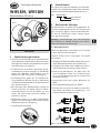
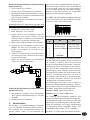
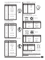
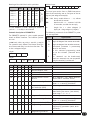
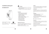
Abb. 1: Montagehinweise
DEUTSCH
1. Gewährleistungshinweise
Lesen Sie vor der Montage und der Inbetriebnahme
dieses Dokument sorgfältig durch. Beachten Sie zu
Ihrer eigenen Sicherheit und der Betriebssicherheit
alle Warnungen und Hinweise.
Ihr Produkt hat unser Werk in geprüftem und be-
triebsbereitem Zustand verlassen. Für den Betrieb
gelten die angegeben Spezifikationen und die
Angaben auf dem Typenschild als Bedingung.
Garantieansprüche gelten nur für Produkte der
Firma SIKO GmbH. Bei dem Einsatz in Verbindung
mit Fremdprodukten besteht für das Gesamtsystem
kein Garantieanspruch.
Bei Störungen oder Geräteausfällen sollten Sie
niemals versuchen, die Geräte selbst zu öffnen.
Ansonsten setzen Sie sich der Gefahr aus, mit
Teilen, die unter hoher Spannung stehen, in
Kontakt zu geraten.
Reparaturen dürfen nur im Werk vorgenommen
werden. Für weitere Fragen steht Ihnen die Firma
SIKO GmbH gerne zur Verfügung.
Fremdmagnete fernhalten.
•
•
•
•
•
•
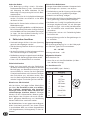
2. Identifikation
Das Typenschild zeigt den Gerätetyp mit Varianten-
nummer. Die Lieferpapiere ordnen jeder Varianten-
nummer eine detaillierte Bestellbezeichnung zu.
z.B. WH58M-0023
Varianten-Nr.
Geräte-Typ
3. Mechanische Montage
Die Montage darf nur gemäß der angegebenen IP-
Schutzart vorgenommen werden. Das System muss
ggfs. zusätzlich gegen schädliche Umwelteinflüs-
se, wie z.B. Spritzwasser, Staub, Schläge, Tempe-
ratur geschützt werden.
Achtung! Radialdichtringe sind Verschleißteile!
Die Schutzart ist deshalb abhängig von Lebens-
dauer und Zustand der Dichtringe.
3.1 Montagehinweise
Gehen Sie sorgfältig mit dem Geber um. Es handelt
sich um ein Präzisionsmessgerät.
Folgende Punkte führen unverzüglich zum Verfall
der Garantie:
Zerlegen oder Öffnen des Gebers (soweit dies nicht in
dieser Benutzerinformation beschrieben wird).
Schläge auf den Geber oder die Welle, da dadurch
interne Elemente beschädigt werden können.
Mechanische Bearbeitung der Welle oder des
Flansches (Bohren, Fräsen, usw.). Hierdurch kann
es zu schweren Beschädigungen der inneren Teile
des Gebers kommen.
Unzulässige axiale oder radiale Belastung der
Welle.
Unsachgemäße Befestigung des Gebers.
Die Verschlussschraube am Gehäuse sollte nach
dem Anbau des Gebers für Einstellungs-/ und
Diagnosearbeiten zugänglich sein.
•
•
•
•
•
•
Benutzerinformation
WH58M, WV58M
Winkelkodierer Multiturn

2 WH58M, WV58M Datum 01.09.2008 Art.Nr. 82679 Änd. Stand 322/08
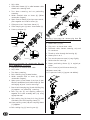
Ansichtseite =
Steckseite
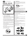
Anbau des Gebers
Die Befestigung erfolgt mittels Schrauben,
Drehmomentabstützung oder Servoklammern
und Klemmung der Welle. Montieren Sie den
Geber möglichst verspannungsfrei und mit Dreh-
momentstütze.
Kräfte dürfen nicht durch das Gehäuse übertragen
werden. Sie dürfen ausschließlich an der Welle
des Geräts wirken.
Beachten Sie die maximalen axialen und radialen
Wellenbelastungen.
Achten Sie auf geringen Wellen- und Winkelversatz.
Bei nicht korrekter axialer oder winkliger Stellung
zwischen Welle und Flansch entstehen Spannungen
im Lager, die über erhöhte Erwärmung bis zur
Zerstörung der Lager führen können.
4. Elektrischer Anschluss
Steckverbindungen dürfen nicht unter Spannung
gesteckt oder abgezogen werden!
Alle Verdrahtungsarbeiten dürfen nur spannungs-
los erfolgen.
Vor dem Einschalten sind alle Leitungsanschlüsse
und Steckverbindungen zu überprüfen.
Die Betriebsspannung muss gemeinsam mit der Folge-
elektronik (z.B. Steuerung) eingeschaltet werden.
Litzen sind mit Aderendhülsen zu versehen.
Sicherheitshinweise:
Wenn durch den Ausfall oder eine Fehlfunktion
des Gebers eine Gefährdung von Mensch oder eine
Beschädigung von Betriebseinrichtungen nicht
auszuschließen ist, so muss dies durch geeignete
Sicherheitsmaßnahmen wie Schutzvorrichtungen
oder Endschalter usw. verhindert werden, bzw.
muss das Gerät außer Betrieb gesetzt und gegen
unbeabsichtigtes Einschalten gesichert werden.
Hinweise zur Störsicherheit
Alle Anschlüsse sind gegen äußere Störeinflüsse
geschützt. Der Einsatzort ist aber so zu wählen,
dass induktive, magnetische oder kapazitive
Störungen nicht auf den Geber oder deren An-
schlussleitungen einwirken können! Störungen
können z.B. von Schaltnetzteilen, Motoren, getak-
teten Reglern oder Schützen verursacht werden.
Durch geeignete Kabelführung und Verdrahtung
können Störeinflüsse vermindert werden.
Der Winkelkodierer ist zwar gegen externe Magnet-
felder hinreichend geschützt, von einem Einsatz
in unmittelbarer Nähe von starken Magnetfeldern
(z.B. Magnetbremsen, Haftmagneten) ist aber ab-
zuraten!
•
•
•
•
•
•
•
•
•
•
Erforderliche Maßnahmen:
Nur geschirmtes Kabel verwenden. Litzenquerschnitt
der Leitungen min. 0,14mm², max. 0,5mm².
Die Verdrahtung von Abschirmung und Masse (0V)
muss sternförmig und großflächig erfolgen.
Kabelschirm beidseitig auflegen.
Der Anschluss des Schirms an den Potentialausgleich
muss großflächig (niederimpedant) erfolgen.
Der Geber muss in möglichst großem Abstand von
Leitungen eingebaut werden, die mit Störungen
belastet sind; ggfs. sind zusätzliche Maßnahmen
wie Schirmbleche oder metallisierte Gehäuse
vorzusehen.
Schützspulen müssen mit Funkenlöschgliedern
beschaltet sein.
Leitungsführung parallel zu Energieleitungen ist
zu vermeiden.
Spannungsversorgung
Die Spannungsversorgung ist u.a. den Lieferpapie-
ren oder dem Typenschild zu entnehmen.
10 ... 30 VDC
Leistungsaufnahme: <1W
Allgemeine Hinweise
Bitte beachten Sie:
Löten Sie nur mit dem Feinlötkolben (15 Watt ...
max. 50 Watt Leistung)
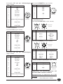
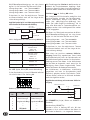
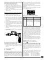
4.1 Anschlussart E2
Schnittstelle SSI (12pol. Stecker)
Pin Belegung
1 GND
2 +UB
3 SSI Takt+
4 SSI Takt-
5 SSI Daten+
6 SSI Daten-
7-9 ---
10 RS485 DÜA
11 ---
12 RS485 DÜB
•
•
•
•
•
•
•
•

WH58M, WV58M Datum 01.09.2008 Art.Nr. 82679 Änd. Stand 322/08 3
Ansichtseite =
Steckseite
Ansichtseite =
Steckseite
Ansichtseite =
Steckseite
Ansichtseite =
Steckseite
Ansichtseite =
Steckseite
IN OUT
Ansichtseite =
Steckseite
IN OUT
Ansichtseite =
Steckseite
Schnittstelle SSI mit ext. Kalibriereingang
(12pol. Stecker)
Pin Belegung
1 GND
2 +UB
3 SSI Takt+
4 SSI Takt-
5 SSI Daten+
6 SSI Daten-
7 ---
8 externer Kalibriereingang
9 ---
10 RS485 DÜA
11 ---
12 RS485 DÜB
4.2 Anschlussart E4
Schnittstelle SSI (12pol. Stecker)
Pin Belegung
A SSI Daten-
B SSI Daten+
C SSI Takt-
D SSI Takt+
E +UB
F GND
G ---
H RS485 DÜA
J ---
K RS485 DÜB
L-M ---
Schnittstelle SSI mit ext. Kalibriereingang
(12pol. Stecker)
Pin Belegung
A SSI Daten-
B SSI Daten+
C SSI Takt-
D SSI Takt+
E +UB
F GND
G ---
H RS485 DÜA
J ---
K RS485 DÜB
L externer Kalibriereingang
M ---
Schnittstelle SIKONETZ-3 (7pol. Stecker)
Pin Belegung
1 DÜA
2 DÜB
3 GND
4 ---
5 +UB
6 ---
7 ---
4.3 Anschlussart E12
Schnittstelle Profibus-DP (2x 5pol. Stecker)
Pin Belegung IN Belegung OUT
1 --- VP (2P5)
2 BUS-A BUS-A
3 --- DGND (2M)
4 BUS-B BUS-B
5 --- Schirm
Schnittstelle CANopen (2x 5pol. Stecker)
Pin Belegung IN Belegung OUT
1 --- ---
2 --- ---
3 CAN_GND CAN_GND
4 CAN_H CAN_H
5 CAN_L CAN_L
Versorgung Profibus-DP/CANopen (4pol. Stecker)
Pin Belegung
1 +UB
2 ---
3 GND
4 ---
Gegenstecker und Kabelverlängerungen sind
bei Firma SIKO als Zubehör erhältlich:
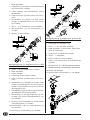
Montageanweisung für Gegenstecker E2 mit SSI
(Zubehör)
Teile 1 ... 3 über Kabelmantel schieben.1.

4 WH58M, WV58M Datum 01.09.2008 Art.Nr. 82679 Änd. Stand 322/08
Schirm
Schirm
Schirm
Schirm
Buchsenteil
Stiftteil
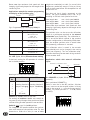
Montageanweisung für Gegenstecker gewinkelt E4
mit SSI oder SIKONETZ-3 (Zubehör)
Dichtungen (1) montieren (3x).
Teile 2 ... 5 auf das Kabel auffädeln.
Kabel abmanteln, Schirm kürzen, Leiter abiso-
lieren und verzinnen.
Litzen durch das Gehäuse (6) führen.
Teile 3 ... 5 montieren.
Druckschraube (2) leicht andrehen.
Litzen nach Anschlussplan an Kontakteinsatz
(8) löten.
Positionshülse (7) in Winkelstellung montieren.
Kontakteinsatz (8) und Distanzhülse (9) einsetzen.
Deckel (10) einhaken.
Druckschraube (2) festziehen (ca. 10-20Ncm).
1.
2.
3.
4.
5.
6.
7.
8.
9.
10.
11.
Kabel abisolieren.
Schirmhülse (4) in Kabel zwischen Kabelmantel
und Flechtschirm schieben.
Schirm umlegen und überstehender Schirm
abschneiden.
Litzen an Einsatz (6) löten (entspr. Anschluss-
plan).
Abstandhülse (5) öffnen und über Litzen
stülpen, zusammendrücken und auf Einsatz
(6) schieben.
Teile 3 ... 6 in Einsatzhülse (7) einschieben.
Überwurfmutter (2) auf Einsatzhülse (7)
schieben.
Adapter (1) aufschrauben.
2.
3.
4.
5.
6.
7.
8.
9.
Montageanweisung für Gegenstecker E4 mit SSI
oder SIKONETZ-3 (Zubehör)
Teile 6 ... 10 über Kabelmantel schieben.
Kabel abisolieren.
Schirm umlegen.
Schirmring (5) auf Litzen schieben.
Litzen an Einsatz (3) löten (entspr. Anschluss-
plan).
Abstandhülse (4) aufweiten und über Litzen
stülpen, zusammendrücken und auf Einsatz (3)
stecken. Schlitz und Nut von (3) und (4) müssen
deckungsgleich sein.
Schirmklemmring (6) an Schirmring (5) drücken,
überstehenden Schirm abschneiden.
Gewindering (2) und Kupplungshülse (7) auf-
schieben und mittels Montagewerkzeug (11)
verschrauben.
Dichtring (8) in Klemmkorb (9) stecken, beides
in Kupplungshülse (7) schieben.
Druckschraube (10) mit Kupplungshülse (7)
verschrauben.
Dichtring (1) in Gewindering (2) schieben.
1.
2.
3.
4.
5.
6.
7.
8.
9.
10.
11.

WH58M, WV58M Datum 01.09.2008 Art.Nr. 82679 Änd. Stand 322/08 5
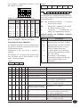
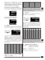
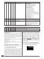
Bedeutung der einzelnen Schalterstellungen:
Schalter-
Nr.
ON OFF
1 Nullsetzen AUS Nullsetzen EIN
2 Drehrichtung I Drehrichtung E
3 Ausgabecode Gray Ausgabecode Binär
4 --- ---
5 --- ---
6 SSI-Mode ---
Mit Schalter 1 kann der Positionswert im Betrieb
auf den Kalibrierwert gesetzt werden. Hierzu muss
der Schalter 1 in Stellung OFF und anschliessend
wieder in Stellung ON gebracht werden. Im Standar-
dauslieferungszustand des Gebers ist der Kalibrier-
wert auf den Wert 0 eingestellt; somit entspricht
die Betätigung dieses Schalters einem Nullsetzen
des Geberpositionswertes. Der Kalibrierwert ist Ge-
berintern nichtflüchtig gespeichert und kann im
Servicemode (siehe Kapitel 5.3) geändert werden.
Die Funktion Nullsetzen sollte nur bei Stillstand
der Geberwelle durchgeführt werden!
Die Einstellungen der Schalter 2 und 3 werden nur
während des Einschaltmoments abgefragt. Änderun-
gen an diesen Schaltern, im eingeschaltetem Zustand
des Gebers, haben keine Auswirkungen mehr.
Schalter 4 und 5 haben keine Funktion.
Schalter 6 muss in Stellung ON stehen.
Die integrierte SSI-Schnittstelle ermöglicht eine
Synchron-Serielle Ausgabe des Positionswertes. Des-
sen Datenformat umfasst eine Breite von 22Bit (bei
10Bit-Single-Turn-Auflösung) bzw. 24Bit (bei 12Bit-
Single-Turn-Auflösung), die im Gray- oder Binärcode
im Tannenbaum-Format ausgegeben werden. Alle
nachfolgenden Bits werden mit "0" ausgegeben.
Die Daten- und Taktsignale entsprechen der RS422.
Ändern der Winkelstellung (nur bei gewinkeltem
Gegenstecker E4):
Druckschraube (2) aufdrehen.
Deckel (10) und Distanzhülse (9) entfernen.
Kontakteinsatz (8) und Positionshülse (7) leicht
herausziehen und in gewünschte Winkelstellung
(90° Schritte) verdrehen.
Deckel und Distanzhülse montieren, Druckschrau-
be aufschrauben.
Montageanweisung für Gegenstecker gewinkelt E12
mit Profibus, CANopen oder Versorgung (Zubehör)
Druckmutter auf das Kabel fädeln.
Kabel abmanteln, Schirm kürzen.
Klappen Sie nun das Schirmgeflecht über den
Kabelmantel nach hinten, isolieren Sie die
einzelnen Adern ca. 10mm ab und versehen Sie
Aderenden mit passenden Aderendhülsen.
Adern durch das Gehäuse fädeln und anschließen.
Klappen Sie das Schirmgeflecht wieder zurück.
Nehmen Sie jetzt die Schirmfolie von dem
Papier ab und kleben Sie die Folie um das
Schirmgeflecht.
Ziehen Sie das Gehäuse bis zum Steckereinsatz
und halten Sie es fest, während Sie den Stecke-
reinsatz aufschrauben.
Drehen Sie die Druckmutter auf das Gehäuse.
Ziehen Sie die Druckmutter fest.
1.
2.
3.
4.
1.
2.
3.
4.
5.
6.
7.
Ändern der Winkelstellung (nur bei gewinkeltem
Gegenstecker E12):
Buchseneinsatz aufdrehen, leicht herausziehen
und in gewünschte Winkelstellung (45° Schritte)
verdrehen.
Buchseneinsatz aufschrauben.
5. Schnittstellen
Verschiedene schnittstellenbezogene Parameter
(je nach gewählter Ausführung) können über ei-
nen 6-poligen bzw. 8-poligen DIP-Schalter ein-
gestellt werden. Dieser ist nach entfernen der
1.
2.
Verschlussschraube am Gehäusedeckel zugänglich.
Die Einstellungen am DIP-Schalter und der Betrieb
im Servicemode (siehe Kap 5.3) sollte möglichst
im nicht angebauten Zustand des Gebers erfolgen.
Dadurch ist ein übersichtlicher und sachgemäßer
Umgang mit dem Messgerät gegeben.
5.1.1 SSI (S6/04, RS422/Synchron Serielles Interface)
In der Grundstellung für den SSI-Betrieb befinden
sich alle Schalter in der Stellung ON.

6 WH58M, WV58M Datum 01.09.2008 Art.Nr. 82679 Änd. Stand 322/08
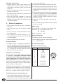
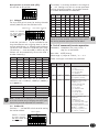
WH58M-SSI
ExtKal-Ein
+UB
GND
SSI
Stromversorgung
Kalibrierwert-Taster
8 (L)
2 (E)
1 (F)
4
+24V/GND
WH/WV58M
Takt+/Takt-/
Daten+/Daten-
z.B. MA10/4
SSI
PT485
RS485
DÜA/DÜB/GND
Netzteil:
2 4 V D C /
500mA
Abb.2: Konfiguration der SIKO-Messanzeige MA10/4:
Die Einstellungen der Schalter 2 und 3 werden nur
während des Einschaltmoments abgefragt. Ände-
rungen an diesen Schaltern im eingeschalteten Zu-
stand des Gebers haben keine Auswirkungen mehr.
Schalter 6 muss in Stellung ON stehen.
Die integrierte SSI-Schnittstelle ermöglicht eine
Synchron-Serielle Ausgabe des Positionswertes.
Dessen Datenformat umfasst eine Breite von
22Bit (bei 10Bit-Single-Turn-Auflösung) bzw.
24Bit (bei 12Bit-Single-Turn-Auflösung), die im
Gray- oder Binärcode im Tannenbaumformat aus-
gegeben werden. Alle nachfolgenend Bits werden
mit"0"ausgegeben.
Die Daten- und Taktsignale entsprechen der RS422.
die SSI Momoflopzeit beträgt typ. 20...25µs, daraus
ergibt sich die minimale Taktrate von 62,5kHz.
Leitungslänge 10m: max. Taktrate 800kHz
Leitungslänge 100m: max. Taktrate 250kHz
Leitungslänge 200m: max. Taktrate 125kHz
Zu beachten ist, dass die mögliche max. Taktrate
und Datensicherheit stark von der Länge der An-
schlussleitung abhängt.
Über einen am Anschluss externer Kalibrier-
eingang (ExtKal-Ein) angebrachten Taster (siehe
Applikationsbeispiel) kann der Positionswert auf
den Kalibrierwert gesetzt werden. Im Standardaus-
lieferungszustand des Gebers ist der Kalibrierwert
auf den Wert 0 eingestellt; somit entspricht die
Betätigung dieses (extern angebrachten) Tasters
einem Nullsetzen des Geberpositionswertes.
Der Kalibrierwert ist Geberintern nichtflüchtig
gespeichert und kann im Servicebetrieb (siehe
Kapitel 6) geändert werden. Die Funktion "Kalib-
rierwert setzen" sollte nur im Stillstand der Geber-
welle durchgeführt werden.
Applikationsschaltung mit externem Kalibrier-
eingang
Die SSI Monoflopzeit beträgt typ. 20...25µs, daraus
ergibt sich die minimale Taktrate von 62,5kHz.
Leitungslänge 10m: max. Taktrate 800kHz
Leitungslänge 100m: max. Taktrate 250kHz
Leitungslänge 200m: max. Taktrate 125kHz
Zu beachten ist, dass die mögliche max. Taktrate
und Datensicherheit stark von der Länge der An-
schlussleitung abhängt.
Applikationsbeispiel zur Geberprogrammierung
und visuelle Positionswertdarstellung
Geber Einstellungen an MA10/4 (SSI)
10Bit Multi-Turn Gebertyp: multi
Format: Tanne
S-Bits: 10
Geberbit: 22
12Bit Multi-Turn Gebertyp: multi
Format: Tanne
S-Bits: 12
Geberbit: 24
10Bit Single-Turn Gebertyp: single
Geberbit: 10
12Bit Single-Turn Gebertyp: single
Geberbit: 12
5.1.2 SSI (S6/04, RS422/SSI, externe Nullstellung)
In der Grundstellung für den SSI-Betrieb befinden
sich alle Schalter in der Stellung ON.
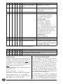
Bedeutung der einzelnen Schalterstellungen:
Schalter-
Nr.
ON OFF
1 --- ---
2 Drehrichtung I Drehrichtung E
3 Ausgabecode Gray Ausgabecode Binär
4 --- ---
5 --- ---
6 SSI-Mode ---
Schalter 1, 4 und 5 haben keine Funktion.
5.2 SIKONETZ-3 (S3/06, RS485 mit SIKONETZ-3
Protokoll)
Grundstellung SIKONETZ-3:
Schalter 6 muss in Stellung OFF sein. Mit den
Schaltern 1 bis 5 wird die Adresse des Gebers im
Binärcode im Bereich 1..31 eingestellt. Werkssei-

WH58M, WV58M Datum 01.09.2008 Art.Nr. 82679 Änd. Stand 322/08 7
Bedeutung der einzelnen Schalterstellungen:
Schalter-Nr. 1
(MSB)
2 3 4 5
(LSB)
6
Adresse 1 ON ON ON ON OFF
SIKONETZ-3 Mode:
Schalter 6 = OFF
Adresse 2 ON ON ON OFF ON
Adresse 3 ON ON ON OFF OFF
.... ... ... ... ... ...
Adresse 29 OFF OFF OFF ON OFF
Adresse 30 OFF OFF OFF OFF ON
Adresse 31 OFF OFF OFF OFF OFF
Die Einstellung der Adresse 0 (Schalter 1 .. 5 auf
ON) ist im SIKONETZ-3 Mode nicht erlaubt!
Protokollbeschreibung SIKONETZ-3
Das SIKONETZ3 Protokoll ist ein busfähiges Proto-
koll auf Basis der RS485 Schnittstelle. Die Schnitt-
stellenparameter lauten:
19200 Baud; 8 Bit; kein Parity; 1 Startbit; 1
Stoppbit
Das Protokoll ist als Master-Slave-System aufge-
baut. Der Geber hat nur Slave-Funktion. Es exis-
tieren 2 Telegrammlängen:
3 Byte:
Adressbyte Befehl Prüfbyte
6 Byte:
Adressbyte Befehl Datenbyte
Low
Datenbyte
Middle
Datenbyte
High
Prüfbyte
Adressbyte:
1 0 A0 A1 A2 A3 A4 0 RR L 1
Start Stop
Das Prüfbyte wird als EXOR-Verknüpfung der restli-
chen 2 bzw. 5 Bytes des Telegramms erzeugt (siehe
Telegrammbeispiel).
A0 ... A4: Binärkodierte Adresse 1 ... 31; Adresse
0 reserviert für Master
RR: Rundruf-Bit = 1 Befehl gilt für alle Ge-
ber, Geber antworten nicht
L: Längen-Bit: 1 = Kurztelegramm (3
Byte); 0 = Langtelegramm (6 Byte)
Folgende Befehle des SIKONETZ3 Protokolls
werden unterstützt:
Spalte Erläuterung
Hex Hexadezimalwert des Befehls
TX Telegrammlänge von Master an Geber
RX Telegrammlänge von Geber an Master
S Übergebener Parameter wird nicht-
flüchtig im Geber gespeichert
P Für diesen Befehl ist es notwendig,
den Programmiermode einzuschalten
(Bef.: 0x32, 0x33)
R Dieser Befehl ist Rundruffähig;
Rundrufbefehle werden von dem/den
angesprochenen Geber(n) nicht
beantwortet!
tig ist Adresse 1 voreingestellt (Schalter 1...4 auf
ON, Schalter 5 auf OFF).
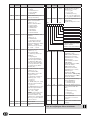
Hex TX RX S P R Funktion Beschreibung
16 3 6 - - - Positionswert auslesen
17 3 6 - - - Absolutwert auslesen
18 3 6 - - - Kalibrierwert auslesen
19 3 6 - - - Offsetwert auslesen
1B 3 6 - - - Gerätekennung auslesen DB-L: Kennung = 19
Hex
; DB-M: Software-
version; DB-H: Hardwareversion
1D 3 6 - - - Zählrichtung auslesen Wert = 0 -> Drehrichtung I;
Wert = 1 -> Drehrichtung E
1E 3 6 - - - Auflösung pro Umdrehung
(APU) des Gebers ausgeben
Wertebereich = 1...65535
28 6 6 S P - Kalibrierwert programmie-
ren
Wert auf den der Positionswert gesetzt
wird, wenn der Sensor genullt wird
(Bef.=0x48). Wertebereich = -2
23
...2
23
-1
29 6 6 S P - Offsetwert programmieren Wertebereich = -2
23
... 2
23
-1
2D 6 6 S P - Zählrichtung programmieren Wert = 0 -> Drehrichtung I;
Wert = 1 -> Drehrichtung E

8 WH58M, WV58M Datum 01.09.2008 Art.Nr. 82679 Änd. Stand 322/08
Hex TX RX S P R Funktion Beschreibung
2E 6 6 S P - Auflösung (APU) program-
mieren
Wertebereich = 1...65535
32 3 3 - - - Programmiermode Ein Programmiermode muss "Ein" sein, um
Parameter (0x28, 0x29 und 0x2d) zu
programmieren
33 3 3 - - - Programmiermode Aus
3A 3 6 - - - Systemstatus ausgeben Datenbyte-Low:
Bit 3: Positionswert eingefroren
Bit 5: Programmierzustand EIN
restliche Bits nicht relevant
Datenbyte-Middle:
Bit 8: Fehler 01 aufgetreten
Bit 9: Fehler 02 aufgetreten
Bit 10: Fehler 03 aufgetreten
Bit 11: Fehler 05 aufgetreten
Bit 13: Batteriezustandswarnung (Bit
gesetzt = Batteriespannung nähert sich
der untersten tolerierbaren Grenze)
Bit 14: Batteriezustand (Bit gesetzt =
Batteriespannung zu niedrig)
restliche Bits nicht relevant
Datenbyte-High:
alle Bits immer Wert 0
3B 3 3 - - - Systemstatus löschen Systemstatus Byte 2+3 gelöscht
48 3 3 S P - Sensor nullen Positionswert wird auf Kalibrierwert gesetzt
4F 3 3 - - R Positionswert einfrieren Positionswert wird eingefroren. Zustand
wird durch auslesen des Positionswertes
zurückgesetzt. Dient zum synchronisier-
ten Auslesen mehrer Geber.
Der Slave (Geber) sendet ggfs. folgende Fehlermeldung:
Hex TX RX S P R Fehlerbeschreibung
82 - 3 - - - Datenübertragungsfehler Prüfsumme
83 - 3 - - - Unzulässiger oder unbekannter Befehl
85 - 3 - - - Unzulässiger Wert (Parameter Programmierung)
Synchronisation:
Eine Byte-/Telegrammsynchronisation erfolgt über
"Timeout": Der Abstand der einzelnen Bytes ei-
nes Telegramms dürfen einen Wert von 10ms nicht
übersteigen. Falls ein angesprochener Sensor nicht
antwortet, so darf der Master frühestens nach
30ms erneut ein Telegramm senden.
Telegrammbeispiel, Master fordert Positionswert
des Sensors 7 an:
Master sendet (hex): 87 16 91
Kurztelegramm an Adresse 7; Befehl 16H; Prüfbyte 91H
Sensor antwortet (hex): 07 16 03 02 00 10
Langtelegramm von Adresse 7; Befehl 16H; Pos.-
Wert: 203H= 515
Dez
; Prüfsumme 10H
5.3 Servicemode (RS485-Mode)
Der Servicemode ist in beiden Schnittstellen-
varianten verfügbar (SSI bzw. SIKONETZ-3). Die
Kommunikation mit dem Geber erfolgt über die
Signale DÜA und DÜB. In der Schnittstellenvari-
ante SSI ist der Servicemode permanent verfügbar
(DIP-Schalter 6 muss in Stellung ON stehen), in
der Schnittstellenvariante SN3 ist die unten ge-
zeigte DIP-Schaltereinstellung massgebend. Nach
Durchführung der Servicemode-Einstellungen sind
die DIP-Schalter-Einstellungen entsprechend der
Schnittstelle wieder vorzunehmen.
In diesem Modus ist es möglich, den Geber mit
Hilfe eines Terminalprogramms (z.B. SIKOTERM.EXE
für PC’s mit WINDOWS©-9x-Betriebssystem [siehe
www.siko.de] bzw. HYPERTERM.EXE für WINDOWS©-

WH58M, WV58M Datum 01.09.2008 Art.Nr. 82679 Änd. Stand 322/08 9
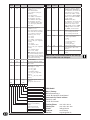
Knotenadresse (Node-ID)
CAN-Baudrate
Schalter 1 ist reser-
viert für Servicezwe-
cke und muss in Stel-
lung ON verbleiben!
Teilnehmeradresse
Schalter 1 ist reser-
viert für Servicezwe-
cke und muss in Stel-
lung ON verbleiben!
Betriebssysteme ab WINDOWS©-NT und höhere
Versionen) über ein einfaches ASCII-Protokoll auf
bestimmte Werte einzustellen bzw. Diagnoseinfor-
mationen abzufragen. Die Verbindung zum PC er-
folgt über einen RS485-zu-RS232-Wandler.
Grundstellung Servicemode (SIKONETZ-3):
Schalter 6 muss in Stellung OFF sein. Sämtliche Schal-
ter 1...5 müssen in Stellung ON stehen (= Adresse 0).
Grundstellung Servicemode (SSI):
Sämtliche Schalter in Stellung ON.
5.4 CANopen
Der 8-polige DIP-Schalter dient zur Einstellung der
Knotenadresse (Node-ID) und der CAN-Baudrate.
Zur Adresseinstellung sind 5 Schalter vorgesehen
(Schalter 4 ... 8), mit dessen Hilfe die Adresse
binärcodiert vergeben wird. Da die Adresse 0 nicht
vergeben werden kann, sind 31 unterschiedliche
Knotenadressen einstellbar. (Werden die Schalter
4 ... 8 doch alle auf ON gestellt [= Adresse 0],
wird Geberintern die Adresse automatisch auf den
Wert 1 gesetzt.)
Schalter 4 Schalter 5 Schalter 6 Schalter 7 Schalter 8 Node-ID
ON ON ON ON ON 1 (!)
ON ON ON ON OFF 1
ON ON ON OFF ON 2
ON ON ON OFF OFF 3
... ... ... ... ... ...
OFF OFF OFF ON OFF 29
OFF OFF OFF OFF ON 30
OFF OFF OFF OFF OFF 31
Mit Schalter 2 und 3 sind 4 unterschiedliche
CAN-Baudraten wählbar: 125kBit/s, 250kBit/s,
500kBit/s und 1000kBit/s.
Schalter 2 Schalter 3 Baudrate
ON ON 125kBit/s
ON OFF 250kBit/s
OFF ON 500kBit/s
OFF OFF 1000kBit/s
Hinweis: Die DIP-Schaltereinstellung wird nur
beim Einschalten des Gebers gelesen. Eine Ände-
rung der Schalterstellungen im laufenden Betrieb
des Gebers hat keine Auswirkung.
5.5 Profibus-DP
Die Schalter 2 ... 8 des DIP-Schalters dienen zur
Einstellung der Teilnehmeradresse.
Die Einstellung der Adresse erfolgt binärcodiert im
Bereich 0 ... 125. Die Einstellungen 126 und 127
sind nicht erlaubt und werden, falls diese Kombi-
nationen erkannt werden, Geberintern der Adresse
125 zugeordnet!
Schal-
ter 2
Schal-
ter 3
Schal-
ter 4
Schal-
ter 5
Schal-
ter 6
Schal-
ter 7
Schal-
ter 8
Teilneh-
mera-
dresse
ON ON ON ON ON ON ON 0
ON ON ON ON ON ON OFF 1
ON ON ON ON ON OFF ON 2
ON ON ON ON ON OFF OFF 3
... ... ... ... ... ... ... ...
OFF OFF OFF ON OFF 123
OFF OFF OFF OFF ON 124
OFF OFF OFF OFF OFF 125
Hinweis: Die DIP-Schaltereinstellung wird nur
beim Einschalten des Gebers gelesen. Eine Ände-
rung der Schalterstellungen im laufenden Betrieb
des Gebers hat keine Auswirkung.
6. Befehlsliste Servicebetrieb
Parameter: 19200 Baud, kein Parity, 8Bit,
1 Stoppbit, ohne Handshake
Ausgabe: ASCII (Binär)
Wertebereiche: 2/3 Byte: 0...65535 / -2
23
...2
23
-1
Es sind Klein- und Großbuchstaben erlaubt.

10 WH58M, WV58M Datum 01.09.2008 Art.Nr. 82679 Änd. Stand 322/08
Befehl Länge
(incl.Return)
Antwort Beschreibung
Px 2/6 xxxx> A/D-Wandler-Wert ausgeben
(Wertebereich 0...1023)
x= 0: sin_x_hall
x= 1: cos_x_hall
x= 2: Batteriespannung
x= 5: sin_x_LK (nur 12Bit Version)
x= 6: cos_x_LK (nur 12Bit Version)
R 1/6 0Xyy> Ausgabe des Flag-Registers in
Hexdarstellung
yy= Wert des Registers in Hex
Sxxxxx 6/2 > Geräteeinstellungen auf
Defaultwerte setzen
xxxxx= 11100 (SIKONETZ-3):
Kalibrierwert, Offestwert,
Nullpunktwert auf 0 setzen;
Zählrichtung= I;
Anzahl Schritte pro Umdr.=
1024 (4096);
Anzahl Umdrehungen= 4096;
Neustart des Gebers
xxxxx= 11000 (SSI):
Kalibrierwert, Offestwert,
Nullpunktwert auf 0 setzen;
Zählrichtung= I;
Ausgabecode= Gray;
Anzahl Schritte= 10Bit (12Bit);
Anzahl Umdrehungen= 12Bit;
Neustart des Gebers
Tx 2/2 > Einstellung der Drehrichtung
(nur bei SIKONETZ-3)
x= 0: Drehrichtung I
x= 1: Drehrichtung E
Vx 2/8 +y,yyV> Anzeige der Batteriespannung
in Volt (nur bei Multi-Turn-
Geber)
x= 0...2
x= 0: Batteriespannung
x= 1: Ref_Gnd
x= 2: Ref_Bandgap
W 1/4 xxxx Positionswert binär
xxxx= 4 Byte im 2-er-Kom-
plement
Z 1/13 ±xxxxxxxxx> Positionswert im ASCII-Format
ausgeben
Beschreibung für Profibus-DP und CANopen
sind der beigefügten CD zu entnehmen.
MSB LSB
0= Drehr. I; 1= Drehr. E
00= Batteriezustand OK
01= Warnung: Batteriesp. kritisch
11 Batterie entladen
(Zustand 10 kann nicht auftreten)
0= Gray; 1= Binär
Befehl Länge
(incl.Return)
Antwort Beschreibung
Ax 2/max.20 max.20 Byte Gerätetyp/Softwareversion
x= 0: Gerät
x= 1: Softwareversion
x= 2: Typ (SSI,SN3)
x= 3: Auflösung
B 1/8 xxxxxx> Multiturnzählerstand (nicht
bei Single-Turn-Geber)
Ey 2/13 ±xxxxxxxxxx> Lesen von Positions-,Nullpunkt,
Kalibrier- und Offsetwert
y= Adresse (0...8)
xxxxxxxx= dezimaler Wert
y= 0: Positionswert
y= 1: Nullpunktwert
y= 2: Kalibrierwert
y= 3: Offsetwert
y= 7: Absolutwert
y= 8: Anzahl Schritte
Fy±xxxxxxx 10/2 > Schreiben von Kalibrier- und
Offsetwert
y= Adresse (2, 3)
y= 2: Kalibrierwert
y= 3: Offsetwert (nicht bei
Singleturn-Geber mit SSI)
Wertebereich Multi-Turn-Geber:
-8388608 ... +8388607
Wertebereich Single-Turn-Ge-
ber: -32759 ... +32758
Gy 2/6 xxxx> Verschiedene Parameter auslesen
y= Adresse (0...7)
xxxx= dezimaler Wert
y= 0: Auflösung (Schritte pro
Umdrehung)
y= 2: Flag-Register
y= 3: Anzahl Umdrehungen
(nicht bei Singleturn-Geber)
y= 5: Multi-Turn-Wert (SSI)
(nicht bei Singleturn-Geber)
y= 6: Single-Turn-Wert (SSI)
y= 7: Summe Single-/Multi-
Turn-Wert (SSI)
Hyxxxx 6/2 > Verschiedene Parameter schreiben
y= Adresse (0...6)
xxxx= dezimaler Wert,
führende Nullen müssen mit
eingegeben werden!
y= 0: Auflösung (Schritte pro
Umdrehung) (min. 0001)
y= 1: gesperrt
y= 2: gesperrt
y= 3: Anzahl Umdr.(0001...4096)
(nicht bei Singleturn-Geber)
y= 4: gesperrt
y= 5: Multi-Turn-Wert (0001...0012)
(nicht bei Singleturn-Geber)
y= 6: Single-Turn-Wert
(0001...0010, 10Bit)
HINWEIS: nach Eingabe einer
der o.a. Parameter werden
automatisch Kalibrier- und
Offsetwert auf 0 zurückgesetzt.
Falls nötig, sind diese Parame-
ter neu zu setzen!
K 1/2 > Software-RESET
L 1/2 > Positionswert auf Kalibrierwert
setzen

WH58M, WV58M Datum 01.09.2008 Art.Nr. 82679 Änd. Stand 322/08 11
Fig. 1: Mounting instructions
WH58M
WV58M
ENGLISH
1. Warranty information
In order to carry out installation correctly, we
strongly recommend this document is read very
carefully. This will ensure your own safety and
the operating reliability of the device.
Your device has been quality controlled, tested
and is ready for use. Please observe all warnings
and information which are marked either directly
on the device or specified in this document.
Warranty can only be claimed for components
supplied by SIKO GmbH. If the system is used
together with other products, there is no warranty
for the complete system.
In case of a breakdown or failure, please never try
to open and repair the device yourself; components
use high voltages.
Repairs should be carried out only at our works.
If any information is missing or unclear, please
contact the SIKO sales staff.
Keep away foreign magnets.
•
•
•
•
•
•
2. Identification
Please check the particular type of unit and type
number from the identification plate. Type number
and the corresponding verion are indicated in the
delivery documentation.
e.g. WH58M-0023
version number
type of unit
3. Installation
For mounting, the degree of protection specified
must be observed. If necessary, protect the unit
against environmental influences such as sprayed
water, dust, knocks, extreme temperatures.
Important information! Radial shaft sealings are
subject to wear! Their protection class therefore
depends on life and condition of sealings.
3.1 Mounting instructions
Please handle the encoder carefully as it is a high-
precision device.
Especially do not:
disassemble or open the encoder (unless specified
in this brochure).
knock on casing or shaft; the encoder's inter-
nal components (eg. the coded disk) could be
damaged.
machine (bore, mill ...) flange or shaft. This could
lead to severe damage inside the encoder.
exceed the values for the maximum axial and
radial shaft load.
mount the encoder incorrectly.
After mounting the encoder, the screw plug on
the housing should be accessible for set-up and
diagnosis purposes.
Otherwise manufacturer's warranty will be invalida-
ted!
•
•
•
•
•
•
User Information
WH58M, WV58M
Multiturn Absolute Encoder

12 WH58M, WV58M Datum 01.09.2008 Art.Nr. 82679 Änd. Stand 322/08
viewing side =
plug-in side
Mounting of the encoder
Fixation either by screws, servo clamps or via
torque pin and shaft clamping. Ensure that
the encoder is mounted without strain and use
torque pin.
Forces must not be transmitted via the housing,
but only via the shaft.
Do not exceed the values for the maximum axial
and radial shaft load.
Ensure accurate shaft alignment. If shaft and
flange are not correctly aligned, strain on the
bearings will result, which will overheat and be
irreparably damaged.
4. Electrical connection
Switch power off before any plug is inserted or
removed!
Any wiring must only be carried out without
power.
Check all lines and connections before switching
on the equipment.
The encoder's and follower electronic's (eg.
control unit) operating supply must be switched
on simultaneously.
Provide stranded wires with ferrules.
Safety precautions:
If personal injury or damage to equipment is
possible should the encoder fail or malfunction,
this must be prevented by suitable safety precau-
tions such as protective devices or limit switches,
etc., or the device must be disabled and secured
against accidental switching on.
Interference and distortion
All connections are protected against the effects
of interference. The location should be selected
to ensure that no inductive, magnetic or capa-
citive interferences can affect the encoder or
the connection lines! Suitable wiring layout and
choice of cable can minimise the effects of inter-
ference (eg. interference caused by SMPS, motors,
cyclic controls and contactors).
Although the angle encoder is sufficiently protec-
ted from external magnetic fields, it is not recom-
mended to use it quite close to strong magnetic
fields (e.g., magnetic brakes, magnetic clamps)!
The following points should be observed:
Only screened cable should be used. Wire cross sec-
tion is to be at least 0,14mm², max. 0,5mm².
Wiring to the screen and ground (0V) must be
•
•
•
•
•
•
•
•
•
•
•
•
secured to a good point.
Screen should be connected to earth at both ends.
It should be ensured that the connection of the
screen and earth should be made to a large surface
area and sound connection to allow minimum
impedance.
The encoder should be positioned well away from
cables with interference; if necessary a protective
screen or metal housing must be provided. The
running of wiring parallel to the mains supply
should be avoided.
Contactor coils must be linked with spark sup-
pression.
The running of wiring parallel to the mains supply
should be avoided.
Power supply
Supply voltage is indicated in the delivery docu-
mentation and on the identification plate.
10 ... 30 VDC
Power consumption: <1W
General information
The following points should be observed:
Use for soldering precision copper bit (performance
15 ... 50 Watt max.)
4.1 Connection type E2
Interface SSI (12-pole plug)
Pin Designation
1 GND
2 +UB
3 SSI Cycle+
4 SSI Cycle-
5 SSI Data+
6 SSI Data-
7-9 ---
10 RS485 DÜA
11 ---
12 RS485 DÜB
•
•
•
•
•
•

WH58M, WV58M Datum 01.09.2008 Art.Nr. 82679 Änd. Stand 322/08 13
viewing side =
plug-in side
viewing side =
plug-in side
viewing side =
plug-in side
viewing side =
plug-in side
viewing side =
plug-in side
IN OUT
viewing side =
plug-in side
IN OUT
viewing side =
plug-in side
Interface SSI with external calibration input
(12-pole plug)
Pin Designation
1 GND
2 +UB
3 SSI Cycle+
4 SSI Cycle-
5 SSI Data+
6 SSI Data-
7 ---
8 ext. calibration input
9 ---
10 RS485 DÜA
11 ---
12 RS485 DÜB
4.2 Connection type E4
Interface SSI (12-pole plug)
Pin Designation
A SSI Data-
B SSI Data+
C SSI Cycle-
D SSI Cycle+
E +UB
F GND
G ---
H RS485 DÜA
J ---
K RS485 DÜB
L-M ---
Interface SSI with external calibration input
(12-pole plug)
Pin Designation
A SSI Data-
B SSI Data+
C SSI Cycle-
D SSI Cycle+
E +UB
F GND
G ---
H RS485 DÜA
J ---
K RS485 DÜB
L ext. calibration input
M ---
Interface SIKONETZ-3 (7-pole plug)
Pin Designation
1 DÜA
2 DÜB
3 GND
4 ---
5 +UB
6 ---
7 ---
4.3 Connection type E12
Interface Profibus-DP (2x 5-pole plug)
Pin Designation IN Designation OUT
1 --- VP (2P5)
2 BUS-A BUS-A
3 --- DGND (2M)
4 BUS-B BUS-B
5 --- screening
Interface CANopen (2x 5-pole plug)
Pin Designation IN Designation OUT
1 --- ---
2 --- ---
3 CAN_GND CAN_GND
4 CAN_H CAN_H
5 CAN_L CAN_L
Supply Profibus-DP/CANopen (4-pole plug)
Pin Designation
1 +UB
2 ---
3 GND
4 ---
Counter-plugs and cable extensions available
as accessories from SIKO:
Mounting instructions for counter-plug E2 with
SSI (accessory)
Slip parts 1 to 3 over outer cable.1.

14 WH58M, WV58M Datum 01.09.2008 Art.Nr. 82679 Änd. Stand 322/08
screening
screening
socket
pin
screening
screening
Strip cable.
Slide shield sleeve (4) in cable between cable
sheath and screening braid.
Turn down screening and cut prodruding
screening.
Solder stranded wires at insert (6) (follow
connection diagram).
Open distance sleeve (5) and put over strands,
press together and slide on insert (6).
Slide parts 3 to 6 into insert sleeve (7).
Slide clamping nut (2) onto insert sleeve (7).
Screw up adaptor (1).
2.
3.
4.
5.
6.
7.
8.
9.
Mounting instructions for counter-plug bent E4
with SSI or SIKONETZ-3 (accessory)
Mount seals (1) (3x).
Slip parts 2 to 5 over outer cable.
Dismantle cable, shorten screening, strip and
tin conductor.
Thread-up wires thruogh the housing (6).
Mount parts 3 to 5.
Turn on the pressure screw (2) very slightly.
Solder wires on insert (8).
Mount positioning sleeve (7) in angled po-
sition.
Set in insert (8) and distance sleeve (9).
Mount cover (10).
Fix pressure screw (2) (approx. 10-20Ncm).
1.
2.
3.
4.
5.
6.
7.
8.
9.
10.
11.
Mounting instructions for counter-plug E4 with
SSI or SIKONETZ-3 (accessory)
Slip parts 6 to 10 over outer cable.
Strip cable.
Turn down screening.
Push shielding ring (5) onto ferrules.
Solder stranded wires at insert (3) (follow
connection diagram).
Open spacer (spacer sleeve 4) and put it over
ferrules, squeeze and push it onto insert (3). Slot
and keyway of parts 3 and 4 must align.
Press shield-clamping ring (6) and shielding ring
(5) together; cut prodruding screening.
Push ring nut (2) and coupling sleeve (7)
together and screw assembly tool (11) using
appropriate tool.
Push sealing ring (8) into pinch ring (9) and
slide both parts into coupling sleeve (7).
Screw pressing screw (10) and coupling sleeve
(7) together.
Push sealing ring (1) into ring nut (2).
1.
2.
3.
4.
5.
6.
7.
8.
9.
10.
11.

WH58M, WV58M Datum 01.09.2008 Art.Nr. 82679 Änd. Stand 322/08 15
should be performed with the encoder unmoun-
ted if possible. This helps ensure clear and proper
handling of the measuring device.
5.1.1 SSI (S6/04, RS422/Synchron Serielles
Interface)
In the basic setting for SSI operation all switches
are in the ON position.
Changing the angle position (only in case of
right angle mating connector E4):
Slight unscrew pressing screw (2).
Remove cover (10) and distance sleeve (9).
Slightly pull out female contact (8) and posi-
tioning sleeve (7) and rotate to desired angular
position (in steps of 90°).
Mount cover and distance sleeve; tighten
pressure screw.
Mounting instructions for counter-plug bent E12
with Profibus, CANopen or Supply (accessory)
Thread pressure nut onto the cable.
Strip the cable sheath, shorten the screen.
Fold the screen sheath about the cable sheath
back, dismantle the single wires (approx. 10
mm) and provide wire ends with suitable wire
end ferrule.
Thread cores through the housing and connect.
Fold the screen sheath back. Take the screen
foil from the paper and stick the foil around the
screen sheath.
Pull the case up to the plug application and
hold on it, while you screw on the plug ap-
plication.
Turn the pressure nut on the case. Tighten the
pressure nut.
1.
2.
3.
4.
1.
2.
3.
4.
5.
6.
7.
Changing the angle position (only in case of
right angle mating connector E12):
Turn on female contact, slightly pull out and
rotate to desired angular position (in steps
of 45°).
Screw on female contact.
5. Interfaces
Depending on the version chosen, various inter-
face-related parameter can be set via the 6-pin
or 8-pin DIP switch. This switch is accessible af-
ter removing the screw plug on the cover of the
housing. Settings by means of the DIP switch and
operation in the service mode (see chapter 5)
1.
2.
Meaning of the individual switch positions:
Switch
No.
ON OFF
1 zero-setting OFF zero-setting ON
2 counting direction I counting direction E
3 output code gray output code binary
4 --- ---
5 --- ---
6 SSI-mode ---
Switch 1 is used for setting the position value to
the calibration value. Put switch 1 in OFF position
and subsequently back to ON position. With facto-
ry settings, the calibration value is set to 0; there-
fore, actuating this switch will result in zeroing of
the encoder position value. The calibration value
is stored non-volatile in the encoder and may be
changed in the service mode (see chapter 5.3).
Zeroing should be done with the encoder shaft
standing still only!
The settings of switches 2 and 3 are scanned du-
ring start-up only. Changes of the positions of these
switches during encoder operation have no effect.
Switches 4 and 5 have no function.
Switch 6 must stand in the ON position.
The integrated SSI interface enables the synchro-
nous-serial output of the position value. Its data
format has a width of 22 bits (in case of 10bit
single-turn resolution) or 24bit (in case of 12bit
single-turn resolution) output in Gray or binary
code in the fir-tree format. All subsequent bits are
output with "0".
The data and clock signals correspond to the
RS422. The typical monoflop time is 20…25 µs
resulting in minimal clock speed of 62.5 kHz.
Line length 10m: max. clock speed 800kHz
Line length 100m: max. clock speed 250kHz
Line length 200m: max. clock speed 125kHz

16 WH58M, WV58M Datum 01.09.2008 Art.Nr. 82679 Änd. Stand 322/08
WH58M-SSI
ExtCal-In
+UB
GND
SSI
Power supply
Pushbutton for calibration value
8 (L)
2 (E)
1 (F)
4
+24V/GND
WH/WV58M
cycle+/cycle-/
data+/data-
e.g. MA10/4
SSI
PT485
RS485
DÜA/DÜB/GND
power pack:
2 4 V D C /
500mA
Fig.2: Programming of SIKO display MA10/4:
Please note that maximum clock speed and data
integrity significantly depend on the length of the
connecting line.
Applications example for encoder programming
and display of the position value
single-turn resolution) or 24bit (in case of 12bit
single-turn resolution) output in Gray or binary
code in the fir-tree format. All subsequent bits are
output with "0".
The data and clock signals correspond to the
RS422. The typical monoflop time is 20…25 µs
resulting in minimal clock speed of 62.5 kHz.
Line length 10m: max. clock speed 800kHz
Line length 100m: max. clock speed 250kHz
Line length 200m: max. clock speed 125kHz
Please note that maximum clock speed and data
integrity significantly depend on the length of the
connecting line.
The position value can be set to the calibration
value via a pushbutton attached to the external
calibration input (ExtKal-Ein). The calibration va-
lue is set to the default value 0 in the standard
encoder configuration as delivered by SIKO; there-
fore, the encoder position value is zeroed when
this (external) pushbutton is actuated.
The calibration value is stored in the encoder
(non-volatile) and can be changed in the service
mode (see chapter 6). The "set calibration value"
function should only be executed during standstill
of the encoder shaft.
Application switch with external calibration
input:
5.2 SIKONETZ-3 (S3/06, RS485 with SIKONETZ-3
protocol)
Basic position of SIKONETZ-3:
Switch 6 must be in the OFF position. Switches
1 to 5 serve to set the encoder address in binary
code in the range of 1 .. 31In the factory setting,
address 1 is pre-set (switches 1 … 4 at ON, switch
5 at OFF).
Encoder Settings on the MA10/4 (SSI)
10bit multi turn encoder type: multi
data format: Tree
S-bits: 10
encoder bit: 22
12bit multi turn encoder type: multi
data format: Tree
S-bits: 12
encoder bit: 24
10bit single turn encoder type: single
encoder bit: 10
12bit single turn encoder type: single
encoder bit: 12
5.1.2 SSI (S6/04, RS422/SSI external zero-setting)
In the basic setting for SSI operation all switches
are in the ON position.
Meaning of the individual switch positions:
Switch
No.
ON OFF
1 --- ---
2 counting direction I counting direction E
3 output code gray output code binary
4 --- ---
5 --- ---
6 SSI-mode ---
Switches 1, 4 and 5 have no function.
The settings of switches 2 and 3 are scanned du-
ring start-up only. Changes of the positions of these
switches during encoder operation have no effect.
Switch 6 must stand in the ON position.
The integrated SSI interface enables the synchro-
nous-serial output of the position value. Its data
format has a width of 22 bits (in case of 10bit

WH58M, WV58M Datum 01.09.2008 Art.Nr. 82679 Änd. Stand 322/08 17
Meaning of the individual switch positions:
Switch No. 1
(MSB)
2 3 4 5
(LSB)
6
address 1 ON ON ON ON OFF
SIKONETZ-3 mode:
switch 6 = OFF
address 2 ON ON ON OFF ON
address 3 ON ON ON OFF OFF
.... ... ... ... ... ...
address 29 OFF OFF OFF ON OFF
address 30 OFF OFF OFF OFF ON
address 31 OFF OFF OFF OFF OFF
In the SIKONETZ-3 mode, setting of address 0
(switch 1 .. 5 at ON) is not allowed!
Protocol description of SIKONETZ-3
The SIKONETZ3 protocol is a bus-capable protocol
based on RS485 interface. The interface parame-
ters are:
19200 baud; 8 bits; no parity; 1 start bit; 1 stop bit
The protocol setup follows the Master-Slave-Sys-
tem; the encoder only has the slave function. The-
re are 2 telegram length:
3 byte:
address byte command check byte
6 byte:
address byte command data byte
Low
data byte
Middle
data byte
High
check byte
Address byte:
1 0 A0 A1 A2 A3 A4 0 RR L 1
start stop
The test byte results from an EXOR-interconnec-
tion of the remaining two or five bytes of the te-
legram (see telegram example).
A0 ... A4: binary coded address 1 ... 31; address
0 reserved for master
RR: broadcast bit = 1; command valid for
all encoders; encoder do not reply
L: length bit: 1 = short telegram (3
bytes); 0 = long telegram (6 bytes)
The following commands of the SIKONETZ-3 proto-
col are supported:
Column Signification
Hex Hexadecimal value of the command
TX length of telegram from master to encoder
RX length of telegram from encoder to master
S transmitted parameter is permanently
stored in the sensor
P for this command programming mode
has to be activated (command 0x32;
0x33)
R this command can be broadcasted;
broadcast commands are not responded
to by the encoder(s) addressed!
Hex TX RX S P R Function Description
16 3 6 - - - read out position value
17 3 6 - - - read out absolut value
18 3 6 - - - read out calibration value
19 3 6 - - - read out offset value
1B 3 6 - - - read out device's charac-
teristics
DB-L: identifier = 19
Hex
; DB-M: software
version; DB-H: hardware version
1D 3 6 - - - read out counting direction Value = 0 -> counting direction I;
Value = 1 -> counting direction E
1E 3 6 - - - output encoder resolution
per revolution (APU)
Value range = 1...65535
28 6 6 S P - program calibration value Value, which position value is set to
when zeroing the sensor (com.=0x48).
Value range = -2
23
...2
23
-1
29 6 6 S P - program offset value Value range = -2
23
... 2
23
-1
2D 6 6 S P - program counting direction Value = 0 -> counting direction I;
Value = 1 -> counting direction E
2E 6 6 S P - program resolution (APU) Value range = 1...65535
32 3 3 - - - programming mode on Programming mode must be "On" for
programming parameters (0x28, 0x29
and 0x2d)
33 3 3 - - - programming mode off

18 WH58M, WV58M Datum 01.09.2008 Art.Nr. 82679 Änd. Stand 322/08
settings set the DIP switches in accordance with
the respective interface. In this mode, the enco-
der can be set to specific values and diagnosis
information can be scanned by means of a simple
ASCII protocol via terminal program (e.g., SIKO-
TERM.EXE for PCs with WINDOWS©-9x operating
system [see www.siko.de] or HYPERTERM.EXE for
WINDOWS© operating systems WINDOWS©-NT or
higher. The connection to the PC is via RS485 to
RS232 converter.
Basic position in service mode (SIKONETZ-3):
Switch 6 must be in the OFF position, All switches
1...5 must be in ON position (=address 0).
Synchronisation:
Byte/ telegram synchronisation is made via "time-
out": the distance between each byte of a tele-
gram must not exceed 10ms. If a sensor does not
respond, the master may only send another tele-
gram after 30ms at the earliest.
Telegram example, Master requests position value
from sensor 7:
Master sends (hex): 87 16 91
short telegram to address 7; command 16H; check
byte 91H
Sensor replies (hex): 07 16 03 02 00 10
long telegram from address 7; command 16H; po-
sition value: 203H= 515Dez; check sum 10H
5.3 Servicemode (RS485-mode)
The service mode is available in both interface
versions (SSI or SIKONETZ-3). Communication with
encoder via DÜA and DÜB signals. Service mode is
permanently available in the SSI interface version
(DIP switch 6 must be at ON position), for the SN3
interface version, the DIP switch position shown
below is relevant. After entering the service mode
Hex TX RX S P R Function Description
3A 3 6 - - - send system status data byte-Low:
bit 3: Position value frozen
bit 5: Programming status ON
remaining bits irrelevant
data byte-Middle:
bit 8: Error 01 occurred
bit 9: Error 02 occurred
bit 10: Error 03 occurred
bit 11: Error 05 occurred
bit 13: Battery status alert (bit set = bat-
tery voltage near lowest tolerable limit)
bit 14: Battery status (bit set = battery
voltage too low)
remaining bits irrelevant
data byte-High:
all bits always 0 value
3B 3 3 - - - cancel system status System status bytes 2+3 deleted
48 3 3 S P - zero sensor Position value is set to calibration value
4F 3 3 - - R freeze position value Position value is frozen. Status is reset
by reading out the position value.
Serves for synchronized reading out of
several encoders.
The slave (encoder) sends the following error message if applicable:
Hex TX RX S P R Error description
82 - 3 - - - check sum data transmission error
83 - 3 - - - invalid or unknown command
85 - 3 - - - invalid value (parameter programming)

WH58M, WV58M Datum 01.09.2008 Art.Nr. 82679 Änd. Stand 322/08 19
Node address (Node-ID)
CAN baud rate
Switch 1 is reserved
for service purposes
and must remain at
the ON position!
Station address
Switch 1 is reserved
for service purposes
and must remain at
the ON position!
Basic position in service mode (SSI):
All switches at ON position.
The address is set binary-encoded in the range of
0 ... 125. Settings 126 and 127 are not permitted
and are assigned to address 125 encoder-internal-
ly if these combinations are detected!
Switch
2
Switch
3
Switch
4
Switch
5
Switch
6
Switch
7
Switch
8
Station
address
ON ON ON ON ON ON ON 0
ON ON ON ON ON ON OFF 1
ON ON ON ON ON OFF ON 2
ON ON ON ON ON OFF OFF 3
... ... ... ... ... ... ... ...
OFF OFF OFF ON OFF 123
OFF OFF OFF OFF ON 124
OFF OFF OFF OFF OFF 125
Hint: The DIP switch setting is only read during
power-on of the encoder. Changing switch positi-
ons during encoder operations has no effect.
6. List of commands/service operation
Parameters: 19200 baud, no parity, 8 bits, 1
stop bit, no handshake
Data code: ASCII (binary)
Value range: 2/3 byte: 0...65535 / -2
23
...2
23
-1
Lower- and upper-case letters are permitted.
Com-
mand
Length
(incl.Return)
Reply Description
Ax 2/max.20 max.20 byte unit type/software version
x= 0: unit
x= 1: software version
x= 2: type (SSI,SN3)
x= 3: resolution
B 1/8 xxxxxx> multi-turn counter reading
(not singleturn encoder)
Ey 2/13 ±xxxxxxxxxx> Reading of position, zero,
calibration and offset value
y= address (0...8)
xxxxxxxx= decimal value
y= 0: position value
y= 1: zero value
y= 2: calibration value
y= 3: offset value
y= 7: absolut value
y= 8: number of steps
Fy±xxxxxxx 10/2 > writing of calibration and
offset value
y= address (2, 3)
y= 2: calibration value
y= 3: offset value (not single-
turn encoder with SSI)
Value range multiturn encoder:
-8388608 ... +8388607
Value range singleturn enco-
der: -32759 ... +32758
5.4 CANopen
The 8-pin DIP switch serves for setting the node
address (Node ID) and the CAN baud rate.
5 switches (switches 4 ... 8) are available for set-
ting the addresses and assigning them in the bi-
nary-encoded format. 31 different node addresses
can be set since address 0 cannot be given away.
(If switches 4 ... 8 are set to ON [= address 0], the
address will be automatically set to the value 1
encoder-internally.)
Switch 4 Switch 5 Switch 6 Switch 7 Switch 8 Node-ID
ON ON ON ON ON 1 (!)
ON ON ON ON OFF 1
ON ON ON OFF ON 2
ON ON ON OFF OFF 3
... ... ... ... ... ...
OFF OFF OFF ON OFF 29
OFF OFF OFF OFF ON 30
OFF OFF OFF OFF OFF 31
4 different CAN baud rates can be selected via
switches 2 and 3: 125Kbit/s, 250Kbit/s, 500Kbit/s
and 1000Kbit/s.
Switch 2 Switch 3 Baud rate
ON ON 125kBit/s
ON OFF 250kBit/s
OFF ON 500kBit/s
OFF OFF 1000kBit/s
Hint: The DIP switch setting is read during power-
on of the encoder only. Changing the switch posi-
tion during encoder operation has no effect.
5.5 Profibus-DP
Switches 2 ... 8 of the DIP switch serve for setting
the station address.

20 WH58M, WV58M Datum 01.09.2008 Art.Nr. 82679 Änd. Stand 322/08
MSB LSB
0= count.direc.I; 1= count.direc.E
00= battery status OK
01= alert: critical battery
voltage
11 battery discharged
(State 10 cannot occur)
0= gray; 1= binar
Com-
mand
Length
(incl.Return)
Reply Description
Gy 2/6 xxxx> read out various parameters
y= address (0...7)
xxxx= decimal value
y= 0: resolution (steps per
revolution)
y= 2: flag-register
y= 3: number of revolution
(not singleturn encoder)
y= 5: multiturn value (SSI)
(not singleturn encoder)
y= 6: singleturn value (SSI)
y= 7: sum single-/multiturn
value (SSI)
Hyxxxx 6/2 > write various parameter
y= address (0...6)
xxxx= decimal value, leading
zeroes must also be entered!
y= 0: resolution (steps per
revolution) (min. 0001)
y= 1: closed
y= 2: closed
y= 3: number of revolutions
(0001...4096) (not singleturn
encoder)
y= 4: closed
y= 5: multiturn value
(0001...0012) (not singleturn
encoder)
y= 6: singleturn value
(0001...0010, 10Bit)
HINT: calibration and offset va-
lues are automatically reset to 0
after entering one of said para-
meters. These parameters should
be set anew if necessary!
K 1/2 > software-RESET
L 1/2 > set position value to calibra-
ration value
Px 2/6 xxxx> output A/D converter value
(value range 0...1023)
x= 0: sin_x_hall
x= 1: cos_x_hall
x= 2: battery voltage
x= 5: sin_x_LK (only 12bit
version)
x= 6: cos_x_LK (only 12bit
version)
R 1/6 0Xyy> output flag register in hex
notation
yy= register value in hex
SIKO GmbH
Werk / Factory:
Weihermattenweg 2
79256 Buchenbach-Unteribental
Postanschrift / Postal address:
Postfach 1106
79195 Kirchzarten
Telefon/Phone +49 7661 394-0
Telefax/Fax +49 7661 394-388
E-Mail inf[email protected]
Internet www.siko.de
Service [email protected]
Com-
mand
Length
(incl.Return)
Reply Description
Sxxxxx 6/2 > set devoce setting to default
xxxxx= 11100 (SIKONETZ-3):
set calibration, offset and zero
point values to 0; counting
direction= I; number of steps
per revolution= 1024 (4096);
number of revolution= 4096;
encoder restart
xxxxx= 11000 (SSI):
set calibration, offset and zero
point values to 0; counting
direction= I; output code=
Gray; number of steps= 10Bit
(12Bit); number of revoluti-
on= 12Bit; encoder restart
Tx 2/2 > setting of sense of rotation
x= 0: counting direction I
x= 1: counting direction E
Vx 2/8 +y,yyV> indication of battery voltage
in volt (only multiturn
encoder)
x= 0...2
x= 0: battery voltage
x= 1: Ref_Gnd
x= 2: Ref_Bandgap
W 1/4 xxxx binary position value
xxxx= 4 byte in two's com-
plement
Z 1/13 ±xxxxxxxxx> output position value in ASCII
format
Please refer to the enclosed CD for the descrip-
tion of Profibus-DP and CANopen.
-
 1
1
-
 2
2
-
 3
3
-
 4
4
-
 5
5
-
 6
6
-
 7
7
-
 8
8
-
 9
9
-
 10
10
-
 11
11
-
 12
12
-
 13
13
-
 14
14
-
 15
15
-
 16
16
-
 17
17
-
 18
18
-
 19
19
-
 20
20


Siko WH58M Installationsanleitung
- Typ
- Installationsanleitung
- Dieses Handbuch eignet sich auch für
in anderen Sprachen
- English: Siko WH58M Installation guide
- eesti: Siko WH58M paigaldusjuhend
Verwandte Artikel
Andere Dokumente
-
Pepperl+Fuchs V1-W-ABG-PG9 Bedienungsanleitung
-
Mettler Toledo Male connector 5-PIN Bedienungsanleitung
-
LinMot MS01-1/D-SSI Installationsanleitung
-
 Maintronic Eventplayer110 DMX Benutzerhandbuch
-
 MICRO-EPSILON wireSENSOR P60 / P96 / P115 Benutzerhandbuch
-
Baumer EAL580-SC - PROFINET Bedienungsanleitung
-
Baumer GBMMW Bedienungsanleitung
-
Rutenbeck 17010554 - KM-USB 3.0 Up 0 rw Benutzerhandbuch
-
ABB AC500 Application Example
-
WAGO PROFIBUS DP/FMS Fieldbus Coupler Benutzerhandbuch

