
Kurzanleitung
MA501 · Datum 31.03.2017 · Art. Nr. 88574 · Änd. Stand 263/16
SIKO GmbH
Weihermattenweg 2
79256 Buchenbach
www.siko-global.com
Telefon: + 49 7661 394-0
Telefax: + 49 7661 394-388
Service: suppor[email protected]
MA501
Messanzeige
Ausführlichere Dokumentationen unter
http://www.siko-global.com/p/ma501
Allgemeine Hinweise
Vor der Installation, einschließlich in Gefahrenbereichen, lesen Sie die Monta-
geanleitung (Download Internet). Sie enthält die Sicherheitsvorschriften, Hin-
weise und technischen Daten, die bei der Installation zu beachten sind. Ände-
rungen sind vorbehalten.
Vorsicht
Damit dieses Produkt zuverlässig funktioniert, muss es sachgemäß transpor-
tiert, aufbewahrt, positioniert und montiert werden. Es muss mit Sorgfalt
betrieben und gewartet werden. Nur entsprechend qualifiziertes Personal darf
dieses Produkt installieren und betreiben.
Sicherheitshinweise
Aus Sicherheitsgründen ist es wichtig, dass Sie die folgenden Punkte lesen und
verstehen, bevor Sie das System installieren:
• Installation, Anschluss, Inbetriebnahme und Wartung ist von Personal aus-
zuführen, das entsprechend qualifiziert ist.
• Es liegt in der Verantwortung des Kunden, dass das betreende Personal vor
der Installation des Gerätes die Anweisungen und Richtungsangaben in die-
ser Anleitung und in der Montageanleitung versteht und befolgt.
• Es liegt in der Verantwortung des Kunden, sicherzustellen, dass die Messan-
zeige richtig angeschlossen und konfiguriert ist.
• Reparatur und Wartung ist nur von Personal durchzuführen, das von SIKO
besonders geschult wurde.
Montage Messanzeige
Für den Schalttafeleinbau gelten empfohlene Abmessungen entsprechend IEC
61554.
Montage Magnetsensor
Der Sensor erfasst die inkrementale Weginformation des Magnetbandes
MB500/1 (linear) oder dem Magnetring MR500 (rotativ).
Der Magnetsensor Bauform L, kann durch zwei beiliegenden Schrauben M3 über
die ø3.1mm Durchgangslöcher befestigt werden.
Montage Magnetband
Das Magnetband muss plan zur Montagefläche bzw. der zu messenden Strecke
aufgeklebt werden. Welligkeiten verschlechtern die Messgenauigkeit.
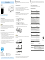
Montageschritte:
• Befestigungsfläche
1
sorgfältig reinigen.
• Schutzfolie
2
des Klebebandes
3
entfernen.
• Magnetband
4
aufkleben.
• Magnetbandoberfläche sorgfältig reinigen.
• Schutzfolie
6
des Abdeckbandes
5
entfernen.
• Abdeckband aufkleben (an beiden Enden leicht überlappen lassen).
• Überlappende Enden des Abdeckbandes gegen Ablösen sichern.
Achtung!
Die Toleranz- und Abstandsmaße müssen über die gesamte Messstrecke einge-
halten werden.
0.1 ... 2mm
Abstand Sensor/Magnetband
<1°
<3°
aktive Seite
Maximale Fluchtungsfehler
<3°
Elektrische Installation
Der Einsatzort ist so zu wählen, dass induktive oder kapazitive Störungen nicht
auf die Messanzeige oder dessen Anschlussleitung einwirken können!
• Das System in möglichst großem Abstand von Leitungen einbauen, die mit
Störungen belastet sind. Schirmbleche oder metallisierte Gehäuse verwen-
den.
Anschluss Spannungsversorgung
Die Spannungsversorgung erfolgt über Anschlusskabel.
Anschluss Batteriekabel
Signal Farbe
1.5VDC (Versorgung Backup) rot
GND schwarz
Anschluss Kabel für Schnittstelle mit Batterie
Signal Farbe E1
GND schwarz
10 ... 24VDC/8mA braun
1.5VDC (Versorgung Backup) rot
Data GND (Schnittstelle RS485) orange
Data B (Schnittstelle RS485-DÜB) gelb
Data A (Schnittstelle RS485-DÜA) grün
Anschluss Kabel für Schnittstelle ohne Batterie
Signal Farbe E1
10 ... 24VDC/8mA braun
Data GND (Schnittstelle RS485) orange/schwarz
Data B (Schnittstelle RS485-DÜB) gelb
Data A (Schnittstelle RS485-DÜA) grün
Anschluss Stecker für Schnittstelle ohne Batterie
Signal Pin E7X
GND 4
24VDC 5
B 6
A 7
nc 1 ... 3
Technische Daten
Elektrische Daten Ergänzung
Betriebsspannung 24VDC ±20% (10 ... 30V) verpolsicher
1.5VDC (1.2 ... 1.6V) Backup
Stromaufnahme 8mA bei 24VDC aktiv
<0.1mA bei 1.5VDC Messsystem aktiv; Dis-
play ausgeschaltet
Ansichtseite =
Steckseite
Stiftkontakt

Quick Start Guide
MA501 · Date 31.03.2017 · Art. No. 88574 · Mod. status 263/16
SIKO GmbH
Weihermattenweg 2
79256 Buchenbach
www.siko-global.com
Phone: + 49 7661 394-0
Fax: + 49 7661 394-388
Service: suppor[email protected]
MA501
Electronic display
For detailed documentation please refer under
http://www.siko-global.com/p/ma501
General information
Prior to installation, including in hazard areas, read the Installation instruc-
tion (download from the internet). It contains the safety instructions, hints
and technical data to be observed during installation. Subject to change with-
out notice.
Caution
In order to ensure reliable functioning of this product, take care to transport,
store, position and mount it appropriately. Exercise care when you operate and
maintain the device. Only properly qualified personnel is authorized to install
and operate this product.
Safety information
It is important for safety reasons that you read and understand the below
instructions before you install the system:
• Installation, connection, commissioning and maintenance shall be done by
properly qualified personnel.
• It is the responsibility of the customer to ensure that the personnel con-
cerned read and follow the instructions and directions of this Guide and of
the Installation instruction.
• It is the responsibility of the customer to ensure that the electronic display
is correctly connected and configured.
• Only personnel specifically trained by SIKO shall execute repair and mainte-
nance work.
Mounting of the electronic display
For switchboard installation the recommended dimensions of IEC 61554 shall
be applied.
Mounting of the magnetic sensor
The sensor senses the incremental travel information of the MB500/1 magnetic
tape (linear) or of the MR500 magnetic rings (rotary).
The magnetic sensor, L versions, is mounted by means of the two attached M3
screws via the ø3.1mm through holes.
Mounting the magnetic tape
Stick the magnetic tape level to the mounting surface or the distance to be
measured. Unevenness impairs measuring accuracy.
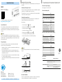
Mounting steps:
• Clean mounting surface
1
carefully.
• Remove protective film
2
of the adhesive tape
3
.
• Stick down the magnetic tape
4
.
• Clean surface of magnetic tape carefully.
• Remove protective film
6
of the cover tape
5
.
• Fix cover tape (both ends should slightly overlap).
• Also fix cover tape's ends to avoid unintentional peeling.
Notice!
The tolerance and gap measures must be observed over the whole measuring
length.
0.1 ... 2mm
Gap sensor/magnetic tape
<1°
<3°
active side
Maximum alignment error
<3°
Electrical Installation
The location should be selected to ensure that no capacitive or inductive inter-
ferences can aect the electronic display or the connection lines!
• When mounting the system keep a maximum possible distance from lines
loaded with interference. Use screening shields or metallized housings.
Connection of power supply
Power supply is via connection cable.
Connection battery cable
Signal Color
1.5VDC (power supply backup) red
GND black
Connection cable for interface with battery
Signal Color E1
GND black
10 ... 24VDC/8mA brown
1.5VDC (power supply backup) red
Data GND (interface RS485) orange
Data B (interface RS485-DÜB) yellow
Data A (interface RS485-DÜA) green
Connection cable for interface without battery
Signal Color E1
10 ... 24VDC/8mA brown
Data GND (interface RS485) orange/black
Data B (interface RS485-DÜB) yellow
Data A (interface RS485-DÜA) green
Connection plug for interface without battery
Signal Pin E7X
GND 4
24VDC 5
B 6
A 7
nc 1 ... 3
Technical data
Electrical data Additional information
Operating voltage 24VDC ±20% (10 ... 30V) reverse polarity protected
1.5VDC (1.2 ... 1.6V) backup
Current consumption 8mA active at 24VDC
<0.1mA at 1.5VDC active measuring sys-
tem; display switched o
viewing side =
plug-in side
plug pin
-
 1
1
-
 2
2


in anderen Sprachen
- English: Siko MA501 Quick start guide
Verwandte Artikel
Andere Dokumente
-
Kübler Limes B2 User Information
-
SICK TTK70 HIPERFACE Safety, TTK50 HIPERFACE safety Motor feeedback systems linear HIPERFACE® Bedienungsanleitung
-
Kübler Limes LA50 Benutzerhandbuch
-
SCHUNK LDT-xS-0200 Assembly And Operating Manual
-
-