SICK Linear encoder TTK70 SSI Bedienungsanleitung
- Typ
- Bedienungsanleitung

Betrie
bsan‐
leitung
B E T R I E B S A N L E I T U N G d e
Linear-Encoder
1 Zu diesem Dokument
Bitte lesen Sie diese Betriebsanleitung sorgfältig, bevor Sie mit dem Linear-
Encoder arbeiten, ihn montieren, in Betrieb nehmen oder warten.
Dieses Dokument ist eine Originalbetriebsanleitung.
1.1 Funktion dieses Dokuments
Diese Betriebsanleitung leitet das technische Personal des Maschinenherstellers
bzw. Maschinenbetreibers zur sicheren Montage, Elektroinstallation, Inbetrieb‐
nahme sowie zum Betrieb und zur Wartung des Linear-Encoders an.
Diese Betriebsanleitung ist allen Personen zugänglich zu machen, die mit
dem Linear-Encoder arbeiten.
Darüber hinaus sind für die Planung und den Einsatz von Linear-Encodern techni‐
sche Fachkenntnisse notwendig, die nicht in diesem Dokument vermittelt werden.
1.2 Symbole und Dokumentkonventionen
WARNUNG
Ein Sicherheitshinweis weist Sie auf konkrete Vorgaben zur Montage und
Installation des Linear-Encoders hin.
Lesen und befolgen Sie Sicherheitshinweise sorgfältig!
HINWEIS
Weist Sie auf nützliche Tipps und Empfehlungen hin.
b
Handlungsanweisungen sind durch einen Pfeil gekennzeichnet. Lesen und
befolgen Sie Handlungsanweisungen sorgfältig.
2 Zu Ihrer Sicherheit
Dieses Kapitel dient Ihrer Sicherheit und der Sicherheit der Anlagenbenutzer.
2.1 Grundlegende Sicherheitshinweise
Für Einbau und Verwendung des Linear-Encoders sowie für die Inbetriebnahme
und wiederkehrende technische Überprüfungen gelten die nationalen und interna‐
tionalen Rechtsvorschriften, insbesondere:
•
Maschinenrichtlinie 2006/42/EG
•
Arbeitsmittelbenutzungsrichtlinie 2009/104/EG
•
Unfallverhütungsvorschriften und Sicherheitsregeln
•
sonstige relevante Sicherheitsregeln
Hersteller und Bediener der Maschine, an der der Linear-Encoder verwendet wird,
müssen alle geltenden Sicherheitsvorschriften und –regeln in eigener Verantwor‐
tung mit der für Sie zuständigen Behörde abstimmen und einhalten.
2.2 Bestimmungsgemäße Verwendung
WARNUNG
Der Linear-Encoder darf nur innerhalb der Grenzen der vorgeschriebenen und
angegebenen technischen Daten, Maße und Toleranzen der Maßbilder und
Betriebsbedingungen verwendet werden; außerdem müssen angegebene
Anzugsdrehmomente eingehalten werden.
Bei jeder anderen Verwendung sowie bei Veränderungen am Gerät – auch im
Rahmen von Montage und Installation – verfällt jeglicher Gewährleistungsan‐
spruch gegenüber der SICK STEGMANN GmbH.
2.3 Anforderungen an die Qualifikation des Personals
Der Linear-Encoder darf nur von befähigten Personen montiert, in Betrieb genom‐
men, geprüft, gewartet und verwendet werden.
Befähigt ist eine Person, wenn folgende Anforderungen erfüllt sind:
•
Geeignete technische Ausbildung des Personals
•
Unterweisung vom Maschinenbetreiber in der Bedienung
•
Zugriff auf diese Betriebsanleitung
3 Montage
Dieses Kapitel beschreibt die Durchführung der Montage des Linear-Encoders.
3.1 Sicherheit
HINWEIS
Die Montage darf nur gemäß der angegebenen IP-Schutzart vorgenommen
werden (siehe Technische Daten).
Das System muss ggf. zusätzlich gegen schädliche Umwelteinflüsse wie z. B.
Spritzwasser, Staub, Schläge, Temperatur geschützt werden.
HINWEIS
Während der Montage Schläge und Stöße auf den Linear-Encoder vermeiden.
WARNUNG
Die Beeinflussung durch magnetische Felder ist zu vermeiden. Insbesondere
dürfen keine Magnetfelder (z. B. Haftmagnete oder andere Dauermagnete) in
direkten Kontakt mit dem Magnetband geraten.
•
Fremdmagnetfelder > ca. 3 ... 4 kA/m (3.8 ... 5 mT) beeinflussen die
Messgenauigkeit.
•
Feldstärken >150 kA/m (>190 mT) verändern die Magnetisierung des
Magnetbandes irreversibel.
Demontage
HINWEIS
Ist eine Demontage des Linear-Encoders erforderlich, so sind die Montage‐
schritte in umgekehrter Reihenfolge durchzuführen.
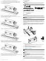
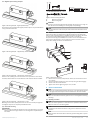
3.2 Montage Magnetband
HINWEIS
Aus technischen Gründen muss bei der Magnetbandlänge (gegenüber der
Messstrecke) ein Zumaß berücksichtigt werden:
•
TTK70: ≥ 80 mm
erf. Bandlänge = Messweg + 80 mm
Messweg5 570
Verfahrrichtung
Bedruckung auf Sensor
Bedruckung auf Band
Abbildung 1: Montage Magnetband
HINWEIS
Die Montage muss plan zur Montagefläche bzw. der zu messenden Strecke
erfolgen. Welligkeiten verschlechtern immer die Messgenauigkeit. Es ist für
ausreichenden mechanischen Schutz zu sorgen (z. B. gegen Schläge und
Vibration).
HINWEIS
Um optimale Verklebungen zu erreichen, müssen alle antiadhäsiven Fremd‐
substanzen (Öl, Fett, Staub, usw.) durch möglichst rückstandslos verduns‐
tende Reinigungsmittel entfernt werden. Als Reinigungsmittel eignen sich
u. a. Ketone (Aceton) oder Alkohole.
HINWEIS
Die Klebeflächen müssen trocken sein und es ist mit höchstmöglichem
Anpressdruck zu verkleben. Die Verklebungstemperatur ist optimal zwischen
20 °C und 30 °C in trockenen Räumen.
HINWEIS
Bei Verklebung langer Bänder sollte die Schutzfolie des Klebebandes über
eine kurze Teilstrecke abgezogen werden, um das Band zu fixieren. Daraufhin
erfolgt das Ausrichten des Bandes. Nach der Ausrichtung kann über die restli‐
che Länge die Schutzfolie, unter gleichzeitigem Andruck des Bandes, seitlich
herausgezogen werden.
b
Befestigungsfläche sorgfältig reinigen.
b
Am Magnetband die Schutzfolie des Klebebandes entfernen.
b
Magnetband unter Berücksichtigung der Verfahrrichtung aufkleben.
b
Magnetbandoberfläche sorgfältig reinigen.
8013390/148V/2019-05-16/de, en TTK70 SSI + Sin/Cos | SICK 1
8013390/148V/2019-05-16
www.sick.com
TTK70 SSI + Sin/Cos
SICK STEGMANN GmbH
Dürrheimer Str. 36
D-78166 Donaueschingen

b
Am Abdeckband die Schutzfolie des Klebebandes entfernen.
b
Abdeckband aufkleben (an beiden Enden leicht überlappen lassen).
b
Die überlappenden Enden des Abdeckbandes gegen Ablösen sichern.
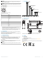
3.3 Montagebeispiele Magnetband
Abbildung 2: Montagebeispiel - Angeschrägtes Schutzband
Die einfache Montageart durch angeschrägtes Schutzband ist nur in sehr
geschützter Umgebung zu empfehlen.
Abbildung 3: Montagebeispiel - Magnetband, stirnseitig verschraubt
Abbildung 4: Montagebeispiel - Magnetband, flächig verschraubt
Bei ungeschützter Umgebung besteht Abschälgefahr. In solchen Fällen sind Mon‐
tagearten mit stirnseitig oder flächig verschraubtem Magnetband geeigneter.
Abbildung 5: Montagebeispiel - Magnetband in einer Nut
Den optimalen Schutz bietet die Montage in einer Nut, die so tief sein sollte, dass
das Magnetband vollständig darin eingebettet werden kann.
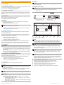
3.4 Montage Lesekopf
WARNUNG
Die Toleranz- und Abstandsmaße müssen über die gesamte Messstrecke ein‐
gehalten werden. Größere Montageabweichungen führen zu unplausiblen
Positionswerten.
0,2
0,4
≤ 0,3
≤ 0,2
1 2
< ± 1°
Abbildung 6: Montagetoleranzen TTK70
1
Ohne Abdeckband
2
Mit Abdeckband
WARNUNG
Sobald das Abdeckband aufgebracht wurde, ist der Bandaufdruck nicht mehr
sichtbar. Es wird empfohlen, das Abdeckband entsprechend zu markieren.
HINWEIS
Die Pfeilrichtung des Sensoraufdruckes muss mit der Pfeilrichtung des Band‐
aufdruckes übereinstimmen.
Die Lage des Sensors zum Magnetband ist genau definiert. Bei der Montage ist
insbesondere zu beachten, dass über die gesamte Messstrecke zwischen Band
und Sensor ein Luftspalt eingehalten wird, unabhängig davon, ob das Band oder
der Sensor bewegt wird. Als Montagehilfe kann die beiliegende Abstandslehre ver‐
wendet werden.
Zur Montage des Lesekopfes (mittig über dem Magnetband) kann der optional
erhältliche Befestigungssatz (2105618) verwendet werden. Der Befestigungssatz
besteht jeweils aus zwei Titanschrauben, Sicherungsscheiben, Buchsen und
Scheiben.
1
2
3
4
Abbildung 7: Montage Lesekopf
1. Titanschraube (4), Sicherungsscheibe (3), Scheibe (2) und Buchse (1) wie
abgebildet montieren.
2. Mit Hilfe der Abstandslehre den Sensor-/Band-Abstand überprüfen.
3. Schraube mit Schraubensicherung sichern.
4. Titanschrauben festziehen. Anzugsdrehmoment: 2,5 ± 0,1 Nm.
4 Elektrische Installation
HINWEIS
Für die Installation des Linear-Encoders die entsprechende Betriebsanleitung
des externen Antriebssystems bzw. der übergeordneten Steuerung beachten!
HINWEIS
Bei der Montage einen spannungsfreien Zustand an betroffenen Maschinen /
Anlagen sicherstellen!
4.1 Schirmanbindung
HINWEIS
Der Einsatzort ist so zu wählen, dass induktive oder kapazitive Störungen
nicht auf den Sensor oder dessen Anschlussleitung einwirken können.
8013390/148V/2019-05-16/de, en TTK70 SSI + Sin/Cos | SICK 2

HINWEIS
Für einen störungsfreien Betrieb ist eine geeignete Schirmanbindung des
Gebers an Masse erforderlich.
HINWEIS
Kabel mit Zugentlastung installieren. Wenn nötig Schleppkette oder Schutz‐
schlauch vorsehen.
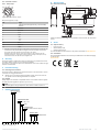
4.2 Anschlussübersicht
4.2.1 M12, 12-polig
Abbildung 8: Anschluss M12, 12-polig
PIN-Belegung M12, 12-polig
PIN Signal
1 Abgleich (Nur für interne Zwecke / auf GND legen)
2 SSI Daten +
3 SSI Daten –
4 SSI Takt –
5 +U
S
6 /Sin
7 Sin
8 /Cos
9 Cos
10 SET
1
11 SSI Takt +
12 GND
1
Dieser Eingang dient dem elektronischen Nullsetzen. Wenn die SET-Leitung für mehr als
1,2 Sekunden an US gelegt wird, nachdem sie zuvor offen oder auf GND gelegt war, ent‐
spricht die Position des Gebers über dem Magnetband dem Wert 0.
Achtung! Der SET-Eingang muss beim Einschalten des Gebers unbeschalten sein oder
auf GND liegen. Wird das elektronische Nullsetzen mithilfe des SET-Eingangs durchge‐
führt, geht die Synchronisation zwischen SSI- und Sin/Cos-Signal verloren.
5 Instandhaltung
Der Linear-Encoder ist wartungsfrei. Bei Defekt ist keine Reparaturmöglichkeit
vorgesehen. Bitte kontaktieren Sie uns bei Reklamationen.
Die Oberfläche des Magnetbandes kann bei starker Verschmutzung gelegentlich
mit einem weichen Lappen gereinigt werden.
6 Außerbetriebnahme
6.1 Umweltgerechtes Verhalten
Der Linear-Encoder ist so konstruiert, dass er die Umwelt so wenig wie möglich
belastet. Er verbraucht nur ein Minimum an Energie und Ressourcen.
b
Handeln Sie auch am Arbeitsplatz immer mit Rücksicht auf die Umwelt.
Beachten Sie deshalb die folgenden Informationen zur Entsorgung.
6.2 Entsorgung
Entsorgen Sie unbrauchbare oder irreparable Geräte immer gemäß den jeweils
gültigen landesspezifischen Abfallbeseitigungsvorschriften.
HINWEIS
Gerne sind wir Ihnen bei der Entsorgung dieser Geräte behilflich. Sprechen
Sie uns an.
7 Bestelldaten
Größe Lesekopf
7 0 70 mm
Elektrische Schnittstelle
A SSI + Sin / Cos
X Linear
Anschlussart
A Stecker M12, 12-polig
Speicherbereich
K 0 2 E²PROM 2048
T T K - 0 - K 0 2
Abbildung 9: Bestellschlüssel
8 Technische Daten
8.1 Maßzeichnungen
M12x1
61,5
40
7014
30
23,6
5,3
6,6 13
5,5
Ø 5,5
Ø 10
8
Abbildung 10: Maßzeichnung TTK70 mit Stecker M12 (alle Maße in mm)
9 Anhang
9.1 Lieferumfang
•
Linear-Encoder
•
Allgemeine Sicherheitshinweise
•
Betriebsanleitung
Weiteres Zubehör finden Sie in der Produktinformation auf www.sick.com
9.2 Konformitäten
Die vollständige EU-Konformitätserklärung finden Sie auf der SICK-Homepage im
Internet:
www.sick.com
8013390/148V/2019-05-16/de, en TTK70 SSI + Sin/Cos | SICK 3

O P E R A T I N G I N S T R U C T I O N S e n
Linear encoder
1 About this document
Please read these operating instructions carefully before using the linear encoder
or mounting it, putting it into operation or servicing it.
This document is the original operating instructions.
1.1 Purpose of this document
These operating instructions provide technical personnel of the machine manu‐
facturer or the machine operator with instructions regarding the safe assembly,
electrical installation, commissioning, operation and maintenance of the linear
encoder.
These operating instructions must be made available to everyone who works with
the linear encoder.
Please note that technical skills not covered by this document are also required
when planning and using SICK linear encoders.
1.2 Symbols and document conventions
WARNING
A safety note informs you of real-world specifications for mounting and
installing the linear encoder.
Read and follow the safety notes carefully.
NOTE
Indicates useful tips and recommendations.
b
Instructions requiring specific action are indicated by an arrow. Carefully
read and follow the instructions for action.
2 Safety information
This chapter concerns your own safety and the safety of the system operator.
2.1 General safety notes
The national and international legal specifications apply to the installation and
use of the linear encoder, to its commissioning, and to technical inspections
repeated at regular intervals, in particular:
•
Machinery Directive 2006/42/EC
•
Work Equipment Directive 2009/104/EC
•
Work safety regulations and safety regulations
•
Any other relevant safety regulations
The manufacturer and operator of the machine on which the linear encoder is
used are responsible for coordinating and complying with all applicable safety
specifications and regulations, in cooperation with the relevant authorities.
2.2 Intended use
WARNING
The linear encoder may be used only within the limits of the prescribed and
specified technical data, dimensions and tolerances of the dimensional draw‐
ings and operating conditions, and the specified tightening torques must be
complied with.
If used in any other way or if alterations are made to the device – including in
the context of mounting and installation – this will render void any warranty
claims directed to SICK STEGMANN GmbH.
2.3 Requirements for the qualification of personnel
The linear encoder may be mounted, put into operation, checked, maintained, or
used only by qualified safety personnel.
Safety personnel is qualified when the following requirements are fulfilled:
•
Appropriate technical training of the personnel
•
Instruction of the machine operator in machine operation
•
Access to these operating instructions
3 Mounting
This chapter describes the mounting of the linear encoder.
3.1 Safety
NOTE
Mounting must only be done in accordance with the specified IP enclosure
rating (see technical data).
If applicable, the system must be protected from damaging environmental
influences such as spray water, dust, impacts and temperature.
NOTE
Impacts or shocks must be prevented when mounting the linear encoder.
WARNING
The influence of magnetic fields must be avoided. In particular, magnet fields
(e.g. holding magnets or other permanent magnets) must not come into
direct contact with the magnetic tape.
•
External magnetic fields > approx. 3 ... 4 kA/m (3.8 ... 5 mT) influence
the measurement accuracy.
•
Field strengths > 150 kA/m (> 190 mT) irreversibly change the magneti‐
zation of the magnetic tape.
Disassembly
NOTE
If the linear encoder has to be removed, the mounting steps are to be carried
out in reverse order.
3.2 Magnetic tape mounting
NOTE
For technical reasons, an additional allowance must be taken into account for
the magnetic tape length (across from the measuring distance):
•
TTK70: ≥ 80 mm
required tape length = measuring section + 80 mm (3.15 inch)
measuring section5
(0.20)
5
(0.20)
70 (2.76)
Travel direction
Marking on sensor Marking on strip
Figure 1: Magnetic tape mounting
NOTE
Mounting must be done level to the mounting surface or the distance to be
measured. Ripples always impair the measurement accuracy. Sufficient
mechanical protection must be ensured (e.g. against impacts and vibrations).
NOTE
To achieve optimal bonding, all anti-adhesive foreign substances (oil, fat,
dust, etc.) must be removed with cleaning agents which evaporate with the
minimum possible level of residue. Among others, ketone (acetone) or alco‐
hol are good cleaning agents.
NOTE
The adhesive surfaces must be dry and the maximum possible contact pres‐
sure must be used for adhesion. An adhesion temperature of 20 °C and
30 °C in dry rooms is optimal.
NOTE
When adhering longer strips of tape, the protective film of the tape should be
removed in shorter sections to fix the tape. Then the tape is aligned. After
alignment, the rest of the protective film can be pulled out from the side while
pressure is applied to the tape at the same time.
b
Carefully clean the mounting surface.
b
Remove the protective film of the tape on the magnetic tape.
b
Adhere the magnetic tape in line with the direction of movement.
b
Carefully clean the magnetic tape surface.
b
Remove the protective film of the tape on the covering tape.
b
Adhere covering tape (slightly overlap at both ends).
b
Secure the overlapping ends of the cover tape from coming loose.
8013390/148V/2019-05-16/de, en TTK70 SSI + Sin/Cos | SICK 4

3.3 Magnetic tape mounting examples
Figure 2: Mounting example - angled protective tape
The simple mounting method with angled protective tape is only recommended in
a very protected environment.
Figure 3: Mounting example - magnetic tape, fastened on front
Figure 4: Mounting example - magnetic tape, fastened flat
There is a risk of peeling off if the environment is not protected. In these cases,
mounting methods with front or flat fastening of the magnetic tape are suitable.
Figure 5: Mounting example - magnetic tape in a slot
Mounting in a slot offers optimal protection. The slot must be deep enough that
the magnetic tape can be completely embedded inside it.
3.4 Read head mounting
WARNING
The tolerance and distance dimensions must be complied with for the entire
measuring distance. Larger deviations in mounting lead to implausible posi‐
tion values.
0.2 (0.01)
0.4 (0.02)
≤ 0.3 (0.01)
≤ 0.2 (0.01)
1 2
< ± 1°
Figure 6: TTK70 mounting tolerances
1
Without covering tape
2
With covering tape
WARNING
As soon as the covering tape has been applied, the tape print is no longer vis‐
ible. We recommend marking the covering tape correspondingly.
NOTE
The arrow direction of the sensor print must match the arrow direction of the
tape print.
The location of the sensor compared to the magnetic tape is exactly defined. Dur‐
ing mounting, make sure that there is an air gap between the tape and sensor
over the entire measuring distance, regardless of whether the tape or the sensor
is moved. The supplied distance gage can be used as a mounting aid.
The optional mounting kit (2105618) can be used to mount the read head (cen‐
trally over the magnetic tape). The mounting kit consists of two titan screws,
safety discs, female connectors and washers each.
1
2
3
4
Figure 7: Read head mounting
1. Mount the titan screw (4), safety disc (3), washer (2) and female connector
(1) as shown.
2. Check the distance between the sensor and tape using the distance gage.
3. Secure screw with screw adhesive.
4. Tighten titan screws. Tightening torque: 2.5 ± 0.1 Nm.
4 Electrical installation
NOTE
Observe the corresponding operating instructions of the external drive system
or the higher-order control system for the installation of the linear encoder.
NOTE
Make sure the affected machines/systems are in a de-energized state during
mounting!
4.1 Shielding connection
NOTE
Select the area of application so that inductive or capacitative faults cannot
affect the sensor or its connecting cable.
NOTE
A suitable encoder shield connection to the ground is required for smooth
operation.
NOTE
Install the cable with strain relief. If necessary, provide a drag chain or protec‐
tive hose.
8013390/148V/2019-05-16/de, en TTK70 SSI + Sin/Cos | SICK 5

4.2 Connection overview
4.2.1 M12, 12-pin
Figure 8: M12 connection, 12-pin
M12 pin assignment, 12-pin
PIN Signal
1 Calibration (for internal purposes only / connect to GND)
2 SSI data +
3 SSI data -
4 SSI clock -
5 +U
S
6 /Sin
7 Sin
8 /Cos
9 Cos
10 SET
1
11 SSI clock +
12 GND
1
This input is for electronic zeroing. If the SET cable is connected to US for more than 1.2
seconds after it had previously been unassigned or connected to GND, the position of
the encoder above the magnetic tape corresponds to the value 0.
Warning! The SET input must be connected to GND or not be connected when the
encoder is switched on. If electronic zeroing is performed using the SET input, the syn‐
chronization between the SSI and Sin/Cos signals is lost.
5 Servicing
The linear encoder is maintenance-free. No repair option is provided in the event
of a defect. Please contact us if you have any complaints.
The surface of the magnetic tape can be cleaned with a soft cloth if there are high
levels of contamination.
6 Decommissioning
6.1 Protecting the environment
The linear encoder is designed to minimize its impact on the environment. It uses
a minimum of energy and resources.
b
Always act in an environmentally responsible manner at work. For this rea‐
son, please note the following information on disposal.
6.2 Disposal
Always dispose of unusable or irreparable devices in accordance with the applica‐
ble waste disposal regulations specific to your country.
NOTE
We will be glad to help you dispose of these devices. Please contact us.
7 Ordering information
Read head size
7 0 70 mm
Electrical interface
A SSI + Sin / Cos
X Linear
Connection type
A M12 male connector, 12-pin
Memory bank
K 0 2 E²PROM 2048
T T K - 0 - K 0 2
Figure 9: Ordering code
8 Technical data
8.1 Dimensional drawings
M12x1
61.5 (2.42)
40 (1.57)
70
14
(0.55)
30 (1.18)
23.6 (0.93)
5.3 (0.21)
6.6
(0.26)
13 (0.51)
5.5
(0.22)
Ø 5.5 (0.22)
Ø 10
(0.39)
8
(0.31)
Figure 10: Dimensional drawing TTK70 with M12 male connector (all dimensions
in mm)
9 Annex
9.1 Scope of delivery
•
Linear encoder
•
General safety notes
•
Operating instructions
You can find additional accessories in the product information at www.sick.com.
9.2 Conformities
The complete EU Declaration of Conformity is available from the SICK homepage
on the Internet:
www.sick.com
8013390/148V/2019-05-16/de, en TTK70 SSI + Sin/Cos | SICK 6
-
 1
1
-
 2
2
-
 3
3
-
 4
4
-
 5
5
-
 6
6


SICK Linear encoder TTK70 SSI Bedienungsanleitung
- Typ
- Bedienungsanleitung
in anderen Sprachen
Verwandte Papiere
-
SICK TTK70 HIPERFACE Safety, TTK50 HIPERFACE safety Motor feeedback systems linear HIPERFACE® Bedienungsanleitung
-
-
-
-
-
Sonstige Unterlagen
-
SCHUNK LDT-xS-0200 Assembly And Operating Manual
-
Kübler Limes B2 User Information
-
Baumer MQR 350A Assembly Instruction
-
-
LinMot MS01-1/D-SSI Installationsanleitung
-
Siko MA564 Installation Instructions Manual
-
Kübler Limes LA50 Benutzerhandbuch
-
Siko MA501 Schnellstartanleitung