ASROCK 880G Pro3 Bedienungsanleitung
- Kategorie
- Motherboards
- Typ
- Bedienungsanleitung

11
11
1
ASRock 880G Pro3 Motherboard
EnglishEnglish
EnglishEnglish
English
Copyright Notice:Copyright Notice:
Copyright Notice:Copyright Notice:
Copyright Notice:
No part of this installation guide may be reproduced, transcribed, transmitted, or trans-
lated in any language, in any form or by any means, except duplication of documen-
tation by the purchaser for backup purpose, without written consent of ASRock Inc.
Products and corporate names appearing in this guide may or may not be registered
trademarks or copyrights of their respective companies, and are used only for identifica-
tion or explanation and to the owners’ benefit, without intent to infringe.
Disclaimer:Disclaimer:
Disclaimer:Disclaimer:
Disclaimer:
Specifications and information contained in this guide are furnished for informational
use only and subject to change without notice, and should not be constructed as a
commitment by ASRock. ASRock assumes no responsibility for any errors or omissions
that may appear in this guide.
With respect to the contents of this guide, ASRock does not provide warranty of any kind,
either expressed or implied, including but not limited to the implied warranties or
conditions of merchantability or fitness for a particular purpose. In no event shall
ASRock, its directors, officers, employees, or agents be liable for any indirect, special,
incidental, or consequential damages (including damages for loss of profits, loss of
business, loss of data, interruption of business and the like), even if ASRock has been
advised of the possibility of such damages arising from any defect or error in the guide
or product.
This device complies with Part 15 of the FCC Rules. Operation is subject to the
following two conditions:
(1) this device may not cause harmful interference, and
(2) this device must accept any interference received, including interference that
may cause undesired operation.
Published January 2011
Copyright©2011 ASRock INC. All rights reserved.
CALIFORNIA, USA ONLY
The Lithium battery adopted on this motherboard contains Perchlorate, a toxic
substance controlled in Perchlorate Best Management Practices (BMP) regulations
passed by the California Legislature. When you discard the Lithium battery in
California, USA, please follow the related regulations in advance.
“Perchlorate Material-special handling may apply, see
www.dtsc.ca.gov/hazardouswaste/perchlorate”
ASRock Website: http://www.asrock.com

22
22
2
ASRock 880G Pro3 Motherboard
EnglishEnglish
EnglishEnglish
English
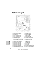
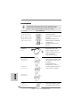
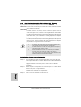
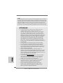
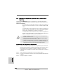
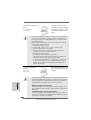
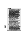
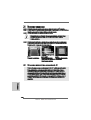
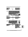
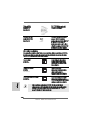
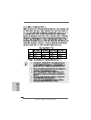
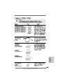
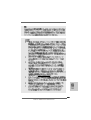
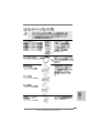
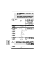
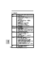
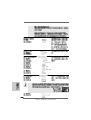
Motherboard LayoutMotherboard Layout
Motherboard LayoutMotherboard Layout
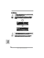
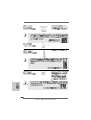
Motherboard Layout
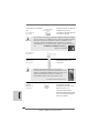
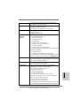
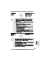
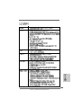
1 ATX 12V Power Connector (ATX12V1) 22 System Panel Header (PANEL1, White)
2 Power Fan Connector (PWR_FAN1) 23 Reset Switch (RSTBTN)
3 AM3+ CPU Socket 24 Power Switch (PWRBTN)
4 CPU Heatsink Retention Module 25 Front Panel IEEE 1394 Header
5 CPU Fan Connector (CPU_FAN2) (FRONT_1394, White)
6 CPU Fan Connector (CPU_FAN1) 26 SPI Flash Memory (32Mb)
7 Chassis Fan Connector (CHA_FAN2) 27 USB 2.0 Header (USB10_11, Blue)
8 2 x 240-pin DDR3 DIMM Slots 28 Clear CMOS Jumper (CLRCMOS1)
(Dual Channel A: DDR3_A1, DDR3_B1; Blue) 29 SB 2.0 Header (USB8_9, Blue)
9 2 x 240-pin DDR3 DIMM Slots 30 SB 2.0 Header (USB6_7, Blue)
(Dual Channel B: DDR3_A2, DDR3_B2; White) 31 Serial Port Connector (COM1)
10 ATX Power Connector (ATXPWR1) 32 Infrared Module Header (IR1)
11 Northbridge Controller 33 HDMI_SPDIF Header
12 Chassis Fan Connector (CHA_FAN3) (HDMI_SPDIF1, White)
13 Southbridge Controller 34 Front Panel Audio Header
14 SATA3 Connector (SATAIII_3, White) (HD_AUDIO1, White)
15 SATA3 Connector (SATAIII_4, White) 35 PCI Slots (PCI2-3)
16 SATA3 Connector (SATAIII_2, White) 36 PCI Express 2.0 x16 Slot (PCIE3; Blue)
17 SATA3 Connector (SATAIII_1, White) 37 PCI Slot (PCI1)
18 SATA3 Connector (SATA3_5, White) 38 PCI Express 2.0 x16 Slot (PCIE2; Blue)
19 Dr. Debug (LED) 39 PCI Express 2.0 x1 Slot (PCIE1; White)
20 Chassis Speaker Header (SPEAKER 1, White) 40 Chassis Fan Connector (CHA_FAN1)
21 Power LED Header (PLED1)

33
33
3
ASRock 880G Pro3 Motherboard
EnglishEnglish
EnglishEnglish
English
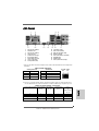
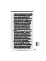
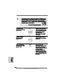
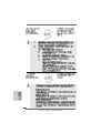
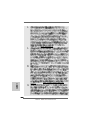
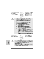
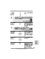
I/O PI/O P
I/O PI/O P
I/O P
anelanel
anelanel
anel
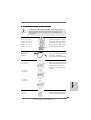
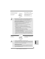
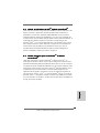
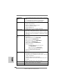
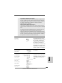
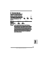
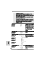
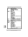
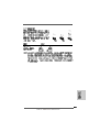
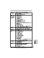
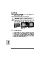
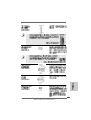
LAN Port
ACT/LINK
LED
SPEED
LED
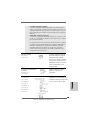
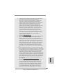
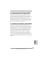
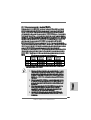
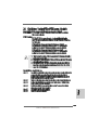
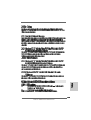
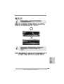
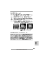
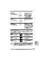
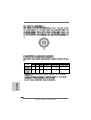
* There are two LED next to the LAN port. Please refer to the table below for the LAN port LED
indications.
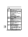
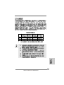
LAN Port LED Indications
Activity/Link LED SPEED LED
Status Description Status Description
Off No Link Off 10Mbps connection
Blinking Data Activity Orange 100Mbps connection
On Link Green 1Gbps connection
1 USB 2.0 Ports (USB45) 10 Microphone (Pink)
2 VGA/D-Sub Port 11 USB 3.0 Port (USB01)
3 USB 2.0 Ports (USB23) 12 IEEE 1394 Port (IEEE 1394)
* 4 LAN RJ-45 Port *** 13 eSATA3 Connector
5 Central / Bass (Orange) 14 Clear CMOS Switch (CLRCBTN)
6 Rear Speaker (Black) 15 VGA/HDMI Port
7 Optical SPDIF Out Port 16 VGA/DVI-D Port
8 Line In (Light Blue) 17 PS/2 Keyboard Port (Purple)
** 9 Front Speaker (Lime)
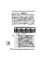
** If you use 2-channel speaker, please connect the speaker’s plug into “Front Speaker Jack”.
See the table below for connection details in accordance with the type of speaker you use.
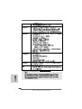
TABLE for Audio Output Connection
Audio Output Channels Front Speaker Rear Speaker Central / Bass Line In
(No. 9) (No. 6) (No. 5) or
Side Speaker
(No. 8)
2 V -- -- --
4VV----
6 VVV--
8 VVVV

44
44
4
ASRock 880G Pro3 Motherboard
To enable Multi-Streaming function, you need to connect a front panel audio cable to the front
panel audio header. After restarting your computer, you will find “Mixer” tool on your system.
Please select “Mixer ToolBox” , click “Enable playback multi-streaming”, and click
“ok”. Choose “2CH”, “4CH”, “6CH”, or “8CH” and then you are allowed to select “Realtek HDA
Primary output” to use Rear Speaker, Central/Bass, and Front Speaker, or select “Realtek
HDA Audio 2nd output” to use front panel audio.
*** eSATA3 connector supports SATA Gen3 in cable 1M.
EnglishEnglish
EnglishEnglish
English

55
55
5
ASRock 880G Pro3 Motherboard
EnglishEnglish
EnglishEnglish
English
1.1.
1.1.
1.
IntroductionIntroduction
IntroductionIntroduction
Introduction
Thank you for purchasing ASRock 880G Pro3 motherboard, a reliable motherboard
produced under ASRock’s consistently stringent quality control. It delivers excellent
performance with robust design conforming to ASRock’s commitment to quality and
endurance.
In this manual, chapter 1 and 2 contain introduction of the motherboard and step-by-step
guide to the hardware installation. Chapter 3 and 4 contain the configuration guide to
BIOS setup and information of the Support CD.
Because the motherboard specifications and the BIOS software might
be updated, the content of this manual will be subject to change without
notice. In case any modifications of this manual occur, the updated
version will be available on ASRock website without further notice. You
may find the latest VGA cards and CPU support lists on ASRock website
as well. ASRock website http://www.asrock.com
If you require technical support related to this motherboard, please visit
our website for specific information about the model you are using.
www.asrock.com/support/index.asp
1.11.1
1.11.1
1.1
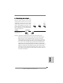
Package ContentsPackage Contents
Package ContentsPackage Contents
Package Contents
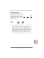
ASRock 880G Pro3 Motherboard
(ATX Form Factor: 12.0-in x 9.6-in, 30.5 cm x 24.4 cm)
ASRock 880G Pro3 Quick Installation Guide
ASRock 880G Pro3 Support CD
2 x Serial ATA (SATA) Data Cables (Optional)
1 x I/O Panel Shield

66
66
6
ASRock 880G Pro3 Motherboard
EnglishEnglish
EnglishEnglish
English
1.21.2
1.21.2
1.2
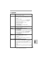
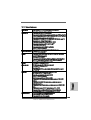
SpecificationsSpecifications
SpecificationsSpecifications
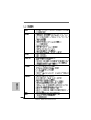
Specifications
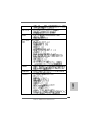
Platform - ATX Form Factor: 12.0-in x 9.6-in, 30.5 cm x 24.4 cm
- All Solid Capacitor design
CPU - Support for Socket AM3+ processors
- Support for Socket AM3 processors: AMD Phenom
TM
II X6 /
X4 / X3 / X2 (except 920 / 940) / Athlon II X4 / X3 / X2 /
Sempron processors
- Supports 8-Core CPU
- Supports UCC feature (Unlock CPU Core) (see CAUTION 1)
- 4 + 1 Power Phase Design
- Supports CPU up to 140W
- Supports AMD’s Cool ‘n’ Quiet
TM
Technology
- FSB 2600 MHz (5.2 GT/s)
- Supports Untied Overclocking Technology (see CAUTION 2)
- Supports Hyper-Transport 3.0 (HT 3.0) Technology
Chipset - Northbridge: AMD 880G
- Southbridge: AMD SB850
Memory - Dual Channel DDR3 Memory Technology (see CAUTION 3)
- 4 x DDR3 DIMM slots
- Support DDR3 1866(OC)/1800(OC)/1600(OC)/1333/1066/800
non-ECC, un-buffered memory (see CAUTION 4)
- Max. capacity of system memory: 32GB (see CAUTION 5)
Expansion Slot - 2 x PCI Express 2.0 x16 slot
(PCIE2 @ x16 mode; PCIE3 @ x4 mode)
- 1 x PCI Express 2.0 x1 slot
- 3 x PCI slots
- Supports ATI
TM
Quad CrossFireX
TM
, CrossFireX
TM
and Hybrid
CrossFireX
TM
Graphics - Integrated AMD Radeon HD 4250 graphics
- DX10.1 class iGPU, Shader Model 4.1
- Max. shared memory 512MB (see CAUTION 6)
- Three VGA Output options: D-Sub, DVI-D and HDMI
- Supports HDMI Technology with max. resolution up to
1920x1200 (1080P)
- Supports Dual-link DVI with max. resolution up to 2560x1600
@ 75Hz
- Supports D-Sub with max. resolution up to 2048x1536
@ 85Hz
- Supports HDCP function with DVI and HDMI ports

77
77
7
ASRock 880G Pro3 Motherboard
EnglishEnglish
EnglishEnglish
English
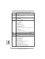
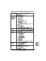
- Supports Full HD 1080p Blu-ray (BD) / HD-DVD playback
with DVI and HDMI ports
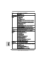
Audio - 7.1 CH HD Audio with Content Protection
(Realtek ALC892 Audio Codec)
- Premium Blu-ray audio support
LAN - PCIE x1 Gigabit LAN 10/100/1000 Mb/s
- Atheros
®
AR8151
- Supports Wake-On-LAN
Rear Panel I/O I/O Panel
- 1 x PS/2 Keyboard Port
- 1 x VGA/D-Sub Port
- 1 x VGA/DVI-D Port
- 1 x HDMI Port
- 1 x Optical SPDIF Out Port
- 4 x Ready-to-Use USB 2.0 Ports
- 1 x eSATA3 Connector
- 2 x Ready-to-Use USB 3.0 Ports
- 1 x RJ-45 LAN Port with LED (ACT/LINK LED and SPEED LED)
- 1 x IEEE 1394 Port
- 1 x Clear CMOS Switch with LED
- HD Audio Jack: Rear Speaker/Central/Bass/Line in/
Front Speaker/Microphone (see CAUTION 7)
SATA3 - 5 x SATA3 6.0 Gb/s connectors, support RAID (RAID 0,
RAID 1, RAID 0+1 and RAID 5), NCQ, AHCI and "Hot Plug"
functions
USB 3.0 - 2 x USB 3.0 ports by Etron EJ168A, support USB 1.0/2.0/3.0
up to 5Gb/s
Connector - 5 x SATA3 6.0Gb/s connectors
- 1 x IR header
- 1 x COM port header
- 1 x IEEE 1394 header
- 1 x HDMI_SPDIF header
- 1 x Power LED header
- CPU/Chassis/Power FAN connector
- 24 pin ATX power connector
- 8 pin 12V power connector
- Front panel audio connector
- 3 x USB 2.0 headers (support 6 USB 2.0 ports)
- 1 x Dr. Debug (7-Segment Debug LED)
Smart Switch - 1 x Clear CMOS Switch with LED
- 1 x Power Switch with LED
- 1 x Reset Switch with LED

88
88
8
ASRock 880G Pro3 Motherboard
EnglishEnglish
EnglishEnglish
English
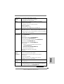
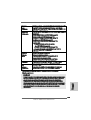
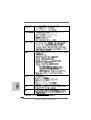
BIOS Feature - 32Mb AMI UEFI Legal BIOS with GUI support
- Supports “Plug and Play”
- ACPI 1.1 Compliance Wake Up Events
- Supports jumperfree
- SMBIOS 2.3.1 Support
- CPU, VCCM, NB, SB Voltage Multi-adjustment
Support CD - Drivers, Utilities, AntiVirus Software (Trial Version), AMD
OverDrive
TM
Utility, AMD Live! Explorer, AMD Fusion, ASRock
Software Suite (CyberLink DVD Suite - OEM and Trial;
Creative Sound Blaster X-Fi MB - Trial)
Unique Feature - ASRock Extreme Tuning Utility (AXTU) (see CAUTION 8)
- Instant Boot
- ASRock Instant Flash (see CAUTION 9)
- ASRock AIWI (see CAUTION 10)
- ASRock APP Charger (see CAUTION 11)
- SmartView (see CAUTION 12)
- ASRock XFast USB (see CAUTION 13)
- Hybrid Booster:
- CPU Frequency Stepless Control (see CAUTION 14)
- ASRock U-COP (see CAUTION 15)
- Boot Failure Guard (B.F.G.)
- Turbo 40 / Turbo 50 GPU Overclocking
- Turbo UCC
Hardware - CPU Temperature Sensing
Monitor - Chassis Temperature Sensing
- CPU/Chassis/Power Fan Tachometer
- CPU Quiet Fan
- CPU/Chassis Fan Multi-Speed Control
- Voltage Monitoring: +12V, +5V, +3.3V, Vcore
OS - Microsoft
®
Windows
®
7 / 7 64-bit / Vista
TM
/ Vista
TM
64-bit
/ XP / XP 64-bit compliant
Certifications - FCC, CE, WHQL
- ErP/EuP Ready (ErP/EuP ready power supply is required)
(see CAUTION 16)
* For detailed product information, please visit our website: http://www.asrock.com
WARNING
Please realize that there is a certain risk involved with overclocking, including adjusting
the setting in the BIOS, applying Untied Overclocking Technology, or using the third-
party overclocking tools. Overclocking may affect your system stability, or even
cause damage to the components and devices of your system. It should be done at
your own risk and expense. We are not responsible for possible damage caused by
overclocking.

99
99
9
ASRock 880G Pro3 Motherboard
EnglishEnglish
EnglishEnglish
English
CAUTION!
1. ASRock UCC (Unlock CPU Core) feature simplifies AMD CPU activation. As
long as a simple switch of the UEFI option “ASRock UCC”, you can unlock the
extra CPU core to enjoy an instant performance boost. When UCC feature is
enabled, the dual-core or triple-core CPU will boost to the quad-core CPU, and
some CPU, including quad-core CPU, can also increase L3 cache size up to
6MB, which means you can enjoy the upgrade CPU performance with a better
price. Please be noted that UCC feature is supported with AM3/AM3+ CPU
only, and in addition, not every AM3/AM3+ CPU can support this function
because some CPU’s hidden core may be malfunctioned.
2. This motherboard supports Untied Overclocking Technology. Please read “Un-
tied Overclocking Technology” on page 38 for details.
3. This motherboard supports Dual Channel Memory Technology. Before you
implement Dual Channel Memory Technology, make sure to read the
installation guide of memory modules on page 14 for proper installation.
4. Whether 1866/1800/1600MHz memory speed is supported depends on the
AM3/AM3+ CPU you adopt. If you want to adopt DDR3 1866/1800/1600
memory module on this motherboard, please refer to the memory support
list on our website for the compatible memory modules.
ASRock website http://www.asrock.com
5. Due to the operating system limitation, the actual memory size may be
less than 4GB for the reservation for system usage under Windows
®
7 /
Vista
TM
/ XP. For Windows
®
OS with 64-bit CPU, there is no such limitation.
6. The maximum shared memory size is defined by the chipset vendor and
is subject to change. Please check AMD website for the latest information.
7. For microphone input, this motherboard supports both stereo and mono modes.
For audio output, this motherboard supports 2-channel, 4-channel, 6-channel,
and 8-channel modes. Please check the table on page 3 for proper connection.
8. ASRock Extreme Tuning Utility (AXTU) is an all-in-one tool to ne-tune
different system functions in a user-friendly interface, which is including
Hardware Monitor, Fan Control, Overclocking, OC DNA and IES. In Hard-
ware Monitor, it shows the major readings of your system. In Fan Control,
it shows the fan speed and temperature for you to adjust. In Overclocking,
you are allowed to overclock CPU frequency for optimal system
performance. In OC DNA, you can save your OC settings as a profile and
share with your friends. Your friends then can load the OC profile to their
own system to get the same OC settings. In IES (Intelligent Energy
Saver), the voltage regulator can reduce the number of output phases to
improve efficiency when the CPU cores are idle without sacrificing
computing performance. Please visit our website for the operation proce-
dures of ASRock Extreme Tuning Utility (AXTU).
ASRock website: http://www.asrock.com

1010
1010
10
ASRock 880G Pro3 Motherboard
EnglishEnglish
EnglishEnglish
English
9. ASRock Instant Flash is a BIOS flash utility embedded in Flash ROM.
This convenient BIOS update tool allows you to update system BIOS
without entering operating systems first like MS-DOS or Windows
®
. With
this utility, you can press <F6> key during the POST or press <F2> key to
BIOS setup menu to access ASRock Instant Flash. Just launch this tool
and save the new BIOS file to your USB flash drive, floppy disk or hard
drive, then you can update your BIOS only in a few clicks without prepar-
ing an additional floppy diskette or other complicated flash utility. Please
be noted that the USB flash drive or hard drive must use FAT32/16/12 file
system.
10. To experience intuitive motion controlled games is no longer only available
at Wii. ASRock AIWI utility introduces a new way of PC gaming operation.
ASRock AIWI is the world's first utility to turn your iPhone/iPod touch as
a game joystick to control your PC games. All you have to do is just to
install the ASRock AIWI utility either from ASRock official website or
ASRock software support CD to your motherboard, and also download the
free AIWI Lite from App store to your iPhone/iPod touch. Connecting your
PC and apple devices via Bluetooth or WiFi networks, then you can start
experiencing the exciting motion controlled games. Also, please do not
forget to pay attention to ASRock official website regularly, we will
continuously provide you the most up-do-date supported games!
ASRock website: http://www.asrock.com/Feature/Aiwi/index.asp
11. If you desire a faster, less restricted way of charging your Apple devices,
such as iPhone/iPod/iPad Touch, ASRock has prepared a wonderful
solution for you - ASRock APP Charger. Simply installing the APP Charger
driver, it makes your iPhone charged much quickly from your computer
and up to 40% faster than before. ASRock APP Charger allows you to
quickly charge many Apple devices simultaneously and even supports
continuous charging when your PC enters into Standby mode (S1), Sus-
pend to RAM (S3), hibernation mode (S4) or power off (S5). With APP
Charger driver installed, you can easily enjoy the marvelous charging
experience than ever.
ASRock website: http://www.asrock.com/Feature/AppCharger/index.asp
12. SmartView, a new function of internet browser, is the smart start page for
IE that combines your most visited web sites, your history, your Facebook
friends and your real-time newsfeed into an enhanced view for a more
personal Internet experience. ASRock motherboards are exclusively
equipped with the SmartView utility that helps you keep in touch with
friends on-the-go. To use SmartView feature, please make sure your OS
version is Windows
®
7 / 7 64 bit / Vista
TM
/ Vista
TM
64 bit, and your browser
version is IE8.
ASRock website: http://www.asrock.com/Feature/SmartView/index.asp
13. ASRock XFast USB can boost USB storage device performance. The
performance may depend on the property of the device.

1111
1111
11
ASRock 880G Pro3 Motherboard
EnglishEnglish
EnglishEnglish
English
14. Although this motherboard offers stepless control, it is not recommended
to perform over-clocking. Frequencies other than the recommended CPU
bus frequencies may cause the instability of the system or damage the
CPU.
15. While CPU overheat is detected, the system will automatically shutdown.
Before you resume the system, please check if the CPU fan on the
motherboard functions properly and unplug the power cord, then plug it
back again. To improve heat dissipation, remember to spray thermal
grease between the CPU and the heatsink when you install the PC system.
16. EuP, stands for Energy Using Product, was a provision regulated by
European Union to define the power consumption for the completed system.
According to EuP, the total AC power of the completed system shall be
under 1.00W in off mode condition. To meet EuP standard, an EuP ready
motherboard and an EuP ready power supply are required. According to
Intel’s suggestion, the EuP ready power supply must meet the standard of
5v standby power efficiency is higher than 50% under 100 mA current
consumption. For EuP ready power supply selection, we recommend you
checking with the power supply manufacturer for more details.

1212
1212
12
ASRock 880G Pro3 Motherboard
EnglishEnglish
EnglishEnglish
English
2.2.
2.2.
2.
InstallationInstallation
InstallationInstallation
Installation
This is an ATX form factor (12.0-in x 9.6-in, 30.5 cm x 24.4 cm) motherboard.
Before you install the motherboard, study the configuration of your chassis to en-
sure that the motherboard fits into it.
Pre-installation PrecautionsPre-installation Precautions
Pre-installation PrecautionsPre-installation Precautions
Pre-installation Precautions
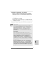
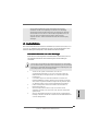
Take note of the following precautions before you install motherboard
components or change any motherboard settings.
Before you install or remove any component, ensure that the
power is switched off or the power cord is detached from the
power supply. Failure to do so may cause severe damage to the
motherboard, peripherals, and/or components.
1. Unplug the power cord from the wall socket before touching any
component.
2. To avoid damaging the motherboard components due to static
electricity, NEVER place your motherboard directly on the carpet or
the like. Also remember to use a grounded wrist strap or touch a
safety grounded object before you handle components.
3. Hold components by the edges and do not touch the ICs.
4. Whenever you uninstall any component, place it on a grounded anti-
static pad or in the bag that comes with the component.
5. When placing screws into the screw holes to secure the motherboard
to the chassis, please do not over-tighten the screws! Doing so may
damage the motherboard.

1313
1313
13
ASRock 880G Pro3 Motherboard
EnglishEnglish
EnglishEnglish
English
2.12.1
2.12.1
2.1
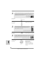
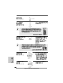
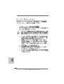
CPU InstallationCPU Installation
CPU InstallationCPU Installation
CPU Installation
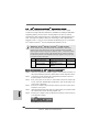
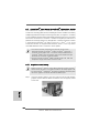
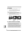
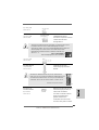
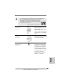
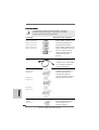
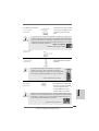
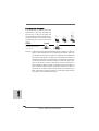
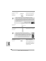
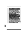
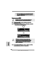
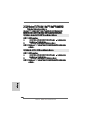
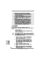
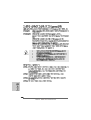
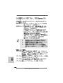
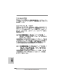
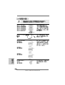
Step 1. Unlock the socket by lifting the lever up to a 90
o
angle.
Step 2. Position the CPU directly above the socket such that the CPU corner with
the golden triangle matches the socket corner with a small triangle.
Step 3. Carefully insert the CPU into the socket until it fits in place.
The CPU fits only in one correct orientation. DO NOT force the CPU
into the socket to avoid bending of the pins.
Step 4. When the CPU is in place, press it firmly on the socket while you push
down the socket lever to secure the CPU. The lever clicks on the side tab
to indicate that it is locked.
2.22.2
2.22.2
2.2
Installation of CPU Fan and HeatsinkInstallation of CPU Fan and Heatsink
Installation of CPU Fan and HeatsinkInstallation of CPU Fan and Heatsink
Installation of CPU Fan and Heatsink
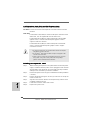
After you install the CPU into this motherboard, it is necessary to install a
larger heatsink and cooling fan to dissipate heat. You also need to spray
thermal grease between the CPU and the heatsink to improve heat
dissipation. Make sure that the CPU and the heatsink are securely fas-
tened and in good contact with each other. Then connect the CPU fan to
the CPU FAN connector (CPU_FAN1, see Page 2, No. 6 or CPU_FAN2, see
Page 2, No. 5). For proper installation, please kindly refer to the instruc-
tion manuals of the CPU fan and the heatsink.
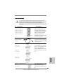
STEP 1:
Lift Up The Socket Lever
STEP 2 / STEP 3:
Match The CPU Golden Triangle
To The Socket Corner Small
Triangle
STEP 4:
Push Down And Lock
The Socket Lever
Lever 90° Up
CPU Golden Triangle
Socker Corner
Small Triangle

1414
1414
14
ASRock 880G Pro3 Motherboard
EnglishEnglish
EnglishEnglish
English
2.3 Installation of Memory Modules (DIMM)2.3 Installation of Memory Modules (DIMM)
2.3 Installation of Memory Modules (DIMM)2.3 Installation of Memory Modules (DIMM)
2.3 Installation of Memory Modules (DIMM)
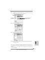
This motherboard provides four 240-pin DDR3 (Double Data Rate 3) DIMM slots,
and supports Dual Channel Memory Technology. For dual channel configuration,
you always need to install identical (the same brand, speed, size and chip-
type) DDR3 DIMM pair in the slots of the same color. In other words, you have to
install identical DDR3 DIMM pair in Dual Channel A (DDR3_A1 and DDR3_B1;
Blue slots; see p.2 No.8) or identical DDR3 DIMM pair in Dual Channel B
(DDR3_A2 and DDR3_B2; White slots; see p.2 No.9), so that Dual Channel
Memory Technology can be activated. This motherboard also allows you to
install four DDR3 DIMMs for dual channel configuration, and please install iden-
tical DDR3 DIMMs in all four slots. You may refer to the Dual Channel Memory
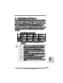
Configuration Table below.
Dual Channel Memory Configurations
DDR3_A1 DDR3_A2 DDR3_B1 DDR3_B2
(Blue Slot) (White Slot) (Blue Slot) (White Slot)
(1) Populated - Populated -
(2) - Populated - Populated
(3)* Populated Populated Populated Populated
*For the configuration (3), please install identical DDR3 DIMMs in all four
slots.
1. If you want to install two memory modules, for optimal compatibility
and reliability, it is recommended to install them in the slots of the
same color. In other words, install them either in the set of blue slots
(DDR3_A1 and DDR3_B1), or in the set of white slots (DDR3_A2
and DDR3_B2).
2. If only one memory module or three memory modules are installed
in the DDR3 DIMM slots on this motherboard, it is unable to activate
the Dual Channel Memory Technology.
3. If a pair of memory modules is NOT installed in the same Dual
Channel, for example, installing a pair of memory modules in
DDR3_A1 and DDR3_A2, it is unable to activate the Dual Channel
Memory Technology .
4. It is not allowed to install a DDR or DDR2 memory module into
DDR3 slot; otherwise, this motherboard and DIMM may be damaged.
5. If you adopt DDR3 1866/1800/1600 memory modules on this
motherboard, it is recommended to install them on DDR3_A2 and
DDR3_B2 slots.

1515
1515
15
ASRock 880G Pro3 Motherboard
EnglishEnglish
EnglishEnglish
English
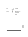
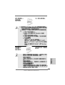
Installing a DIMMInstalling a DIMM
Installing a DIMMInstalling a DIMM
Installing a DIMM
Please make sure to disconnect power supply before adding or
removing DIMMs or the system components.
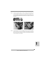
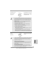
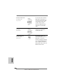
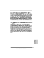
Step 1. Unlock a DIMM slot by pressing the retaining clips outward.
Step 2. Align a DIMM on the slot such that the notch on the DIMM matches the break
on the slot.
The DIMM only fits in one correct orientation. It will cause permanent
damage to the motherboard and the DIMM if you force the DIMM into the
slot at incorrect orientation.
Step 3. Firmly insert the DIMM into the slot until the retaining clips at both ends fully
snap back in place and the DIMM is properly seated.

1616
1616
16
ASRock 880G Pro3 Motherboard
EnglishEnglish
EnglishEnglish
English
2.4 Expansion Slots (PCI and PCI Express Slots)2.4 Expansion Slots (PCI and PCI Express Slots)
2.4 Expansion Slots (PCI and PCI Express Slots)2.4 Expansion Slots (PCI and PCI Express Slots)
2.4 Expansion Slots (PCI and PCI Express Slots)
There are 3 PCI slots and 3 PCI Express slots on this motherboard.
PCI Slots: PCI slots are used to install expansion cards that have the 32-bit PCI
interface.
PCIE Slots:
PCIE1 (PCIE x1 slot; White) is used for PCI Express cards with x1 lane
width cards, such as Gigabit LAN card and SATA2 card.
PCIE2 (PCIE x16 slot; Blue) is used for PCI Express x16 lane width
graphics cards, or used to install PCI Express graphics cards to
support CrossFireX
TM
function.
PCIE3 (PCIE x16 slot; Blue) is used for PCI Express x4 lane width
cards, or used to install PCI Express graphics cards to support
CrossFireX
TM
function.
1. In single VGA card mode, it is recommended to install a PCI Express
x16 graphics card on PCIE2 slot.
2. In CrossFireX
TM
mode, please install PCI Express x16 graphics cards
on PCIE2 and PCIE3 slots.
3. Please connect a chassis fan to motherboard chassis fan connector
(CHA_FAN1, CHA_FAN2 or CHA_FAN3) when using multiple
graphics cards for better thermal environment.
Installing an expansion cardInstalling an expansion card
Installing an expansion cardInstalling an expansion card
Installing an expansion card
Step 1. Before installing the expansion card, please make sure that the power
supply is switched off or the power cord is unplugged. Please read the
documentation of the expansion card and make necessary hardware
settings for the card before you start the installation.
Step 2. Remove the system unit cover (if your motherboard is already installed in
a chassis).
Step 3. Remove the bracket facing the slot that you intend to use. Keep the
screws for later use.
Step 4. Align the card connector with the slot and press firmly until the card is
completely seated on the slot.
Step 5. Fasten the card to the chassis with screws.
Step 6. Replace the system cover.

1717
1717
17
ASRock 880G Pro3 Motherboard
EnglishEnglish
EnglishEnglish
English
2. If you have installed onboard VGA driver from our support CD to your system
already, you can freely enjoy the benefits of dual monitor function after your
system boots. If you haven’t installed onboard VGA driver yet, please install
onboard VGA driver from our support CD to your system and restart your
computer. Then you can start to use dual monitor function on this motherboard.
1. DVI-D and HDMI ports cannot function at the same time. When one of
them is enabled, the other one will be disabled.
2. When you playback HDCP-protected video from Blu-ray (BD) or
HD-DVD disc, the content will be displayed only in one of the two
monitors instead of both monitors.
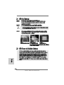
2.5 Dual Monitor and Surround Display Features2.5 Dual Monitor and Surround Display Features
2.5 Dual Monitor and Surround Display Features2.5 Dual Monitor and Surround Display Features
2.5 Dual Monitor and Surround Display Features
Dual Monitor Feature
This motherboard supports dual monitor feature. With the internal VGA output
support (DVI-D, D-Sub and HDMI), you can easily enjoy the benefits of dual monitor
feature without installing any add-on VGA card to this motherboard. This
motherboard also provides independent display controllers for DVI-D, D-Sub and
HDMI to support dual VGA output so that DVI-D, D-sub and HDMI can drive same or
different display contents.
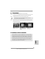
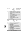
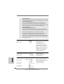
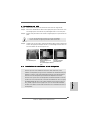
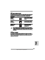
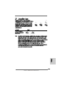
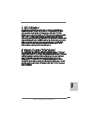
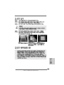
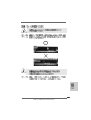
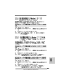
To enable dual monitor feature, please follow the below steps:
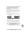
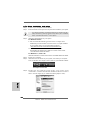
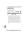
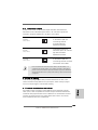
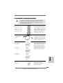
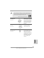
1. Connect DVI-D monitor cable to VGA/DVI-D port on the I/O panel, connect D-Sub
monitor cable to VGA/D-Sub port on the I/O panel, or connect HDMI monitor
cable to HDMI port on the I/O panel.
VGA/DVI-D port
HDMI port
VGA/D-Sub port

1818
1818
18
ASRock 880G Pro3 Motherboard
EnglishEnglish
EnglishEnglish
English
Surround Display Feature
This motherboard supports surround display upgrade. With the internal VGA
output support (DVI-D, D-Sub and HDMI) and external add-on PCI Express VGA
cards, you can easily enjoy the benefits of surround display feature.
Please refer to the following steps to set up a surround display environment:
1. Install the ATI
TM
PCI Express VGA cards on PCIE2 and PCIE3 slots. Please
refer to page 16 for proper expansion card installation procedures for details.
2. Connect DVI-D monitor cable to VGA/DVI-D port on the I/O panel, connect D-Sub
monitor cable to VGA/D-Sub port on the I/O panel, or connect HDMI monitor
cable to HDMI port on the I/O panel. Then connect other monitor cables to the
corresponding connectors of the add-on PCI Express VGA cards on PCIE2
and PCIE3 slots.
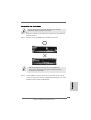
3. Boot your system. Press <F2> to enter UEFI setup. Enter “Share Memory”
option to adjust the memory capability to [32MB], [64MB], [128MB] [256MB] or
[512MB] to enable the function of VGA/D-sub. Please make sure that the value
you select is less than the total capability of the system memory. If you do not
adjust the UEFI setup, the default value of “Share Memory”, [Auto], will disable
VGA/D-Sub function when the add-on VGA card is inserted to this
motherboard.
4. Install the onboard VGA driver and the add-on PCI Express VGA card driver to
your system. If you have installed the drivers already, there is no need to install
them again.
5. Set up a multi-monitor display.
For Windows
®
XP / XP 64-bit OS:
Right click the desktop, choose “Properties”, and select the “Settings” tab
so that you can adjust the parameters of the multi-monitor according to the
steps below.
A. Click the “Identify” button to display a large number on each monitor.
B. Right-click the display icon in the Display Properties dialog that you wish
to be your primary monitor, and then select “Primary”. When you use
multiple monitors with your card, one monitor will always be Primary,
and all additional monitors will be designated as Secondary.
C. Select the display icon identified by the number 2.
D. Click “Extend my Windows desktop onto this monitor”.
E. Right-click the display icon and select “Attached”, if necessary.
F. Set the “Screen Resolution” and “Color Quality” as appropriate for the
second monitor. Click “Apply” or “OK” to apply these new values.
G. Repeat steps C through E for the diaplay icon identified by the number
one, two, three, four, five and six.

1919
1919
19
ASRock 880G Pro3 Motherboard
EnglishEnglish
EnglishEnglish
English
HDCP Function
HDCP function is supported on this motherboard. To use HDCP
function with this motherboard, you need to adopt the monitor that
supports HDCP function as well. Therefore, you can enjoy the
superior display quality with high-definition HDCP encryption
contents. Please refer to below instruction for more details about
HDCP function.
What is HDCP?
HDCP stands for High-Bandwidth Digital Content Protection, a
specification developed by Intel
®
for protecting digital entertainment
content that uses the DVI interface. HDCP is a copy protection
scheme to eliminate the possibility of intercepting digital data
midstream between the video source, or transmitter - such as a
computer, DVD player or set-top box - and the digital display, or
receiver - such as a monitor, television or projector. In other words,
HDCP specification is designed to protect the integrity of content as it
is being transmitted.
Products compatible with the HDCP scheme such as DVD players,
satellite and cable HDTV set-top-boxes, as well as few entertain-
ment PCs requires a secure connection to a compliant display. Due
to the increase in manufacturers employing HDCP in their equipment,
it is highly recommended that the HDTV or LCD monitor you purchase
is compatible.
For Windows
®
7 / 7 64-bit / Vista
TM
/ Vista
TM
64-bit OS:
Right click the desktop, choose “Personalize”, and select the “Display
Settings” tab so that you can adjust the parameters of the multi-monitor
according to the steps below.
A. Click the number ”2” icon.
B. Click the items “This is my main monitor” and “Extend the desktop onto
this monitor”.
C. Click “OK” to save your change.
D. Repeat steps A through C for the display icon identified by the number
three, four, five and six.
6. Use Surround Display. Click and drag the display icons to positions representing
the physical setup of your monitors that you would like to use. The placement
of display icons determines how you move items from one monitor to another.

2020
2020
20
ASRock 880G Pro3 Motherboard
EnglishEnglish
EnglishEnglish
English
2.62.6
2.62.6
2.6
AA
AA
A
TITI
TITI
TI
TMTM
TMTM
TM
Hybrid CrossF Hybrid CrossF
Hybrid CrossF Hybrid CrossF
Hybrid CrossF
ireXireX
ireXireX
ireX
TMTM
TMTM
TM
Operation Guide Operation Guide
Operation Guide Operation Guide
Operation Guide
This motherboard supports ATI
TM
Hybrid CrossFireX
TM
feature. ATI
TM
Hybrid
CrossFireX
TM
brings multi-GPU performance capabilities by enabling an AMD 880G
integrated graphics processor and a discrete graphics processor to operate
simultaneously with combined output to a single display for blisteringly-fast frame
rates. Currently, ATI
TM
Hybrid CrossFireX
TM
Technology is only supported with
Windows
®
Vista
TM
/ 7 OS, and is not available with Windows
®
XP OS. In the future,
ATI
TM
Hybrid CrossFireX
TM
may be supported with Windows
®
XP OS.
Enjoy the benefit of AEnjoy the benefit of A
Enjoy the benefit of AEnjoy the benefit of A
Enjoy the benefit of A
TITI
TITI
TI
TMTM
TMTM
TM
Hybrid CrossF Hybrid CrossF
Hybrid CrossF Hybrid CrossF
Hybrid CrossF
ireXireX
ireXireX
ireX
TMTM
TMTM
TM
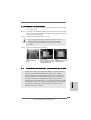
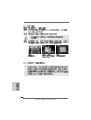
Step 1. Install one compatible PCI Express graphics card to PCIE2 slot (blue). For
the proper installation procedures, please refer to section “Expansion Slots”.
Step 2. Connect the monitor cable to the correspondent connector on the PCI
Express graphics card on PCIE2 slot.
Step 3. Boot your system. Press <F2> to enter UEFI setup. Enter “Advanced”
screen, and enter “North Bridge Configuration”. Then set the option “Sur-
round View” to [Enabled].
Step 4. Boot into OS. Please remove the ATI
TM
driver if you have any VGA driver
installed in your system.
Step 5. Install the onboard VGA driver from our support CD to your system for both
the onboard VGA and the discrete graphics card.
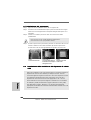
Step 6. Restart your computer. Then you will find “ATI Catalyst Control Center” on
your Windows
®
taskbar.
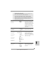
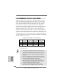
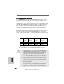
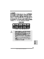
ATI Catalyst Control Center
Vendor Chipset Model Driver
ATI RADEON HD2400XT POWERCOLOR HD2400 XT Support CD 8.71
256MB DDR3
RADEON HD3450 POWERCOLOR AX3450 Support CD 8.71
256MD2-S
What does an ATI
TM
Hybrid CrossFireX
TM
system include?
An ATI
TM
Hybrid CrossFireX
TM
system includes an ATI
TM
Radeon
TM
2400 or ATI
TM
Radeon
TM
3450 series graphics processor and a motherboard based on an AMD
880G integrated chipset, all operating in a Windows
®
Vista
TM
/ 7 environment. Please
refer to below PCI Express graphics card support list for ATI
TM
Hybrid CrossFireX
TM
.
For the future update of more compatible PCI Express graphics cards, please visit
our website for further information.
Seite wird geladen ...
Seite wird geladen ...
Seite wird geladen ...
Seite wird geladen ...
Seite wird geladen ...
Seite wird geladen ...
Seite wird geladen ...
Seite wird geladen ...
Seite wird geladen ...
Seite wird geladen ...
Seite wird geladen ...
Seite wird geladen ...
Seite wird geladen ...
Seite wird geladen ...
Seite wird geladen ...
Seite wird geladen ...
Seite wird geladen ...
Seite wird geladen ...
Seite wird geladen ...
Seite wird geladen ...
Seite wird geladen ...
Seite wird geladen ...
Seite wird geladen ...
Seite wird geladen ...
Seite wird geladen ...
Seite wird geladen ...
Seite wird geladen ...
Seite wird geladen ...
Seite wird geladen ...
Seite wird geladen ...
Seite wird geladen ...
Seite wird geladen ...
Seite wird geladen ...
Seite wird geladen ...
Seite wird geladen ...
Seite wird geladen ...
Seite wird geladen ...
Seite wird geladen ...
Seite wird geladen ...
Seite wird geladen ...
Seite wird geladen ...
Seite wird geladen ...
Seite wird geladen ...
Seite wird geladen ...
Seite wird geladen ...
Seite wird geladen ...
Seite wird geladen ...
Seite wird geladen ...
Seite wird geladen ...
Seite wird geladen ...
Seite wird geladen ...
Seite wird geladen ...
Seite wird geladen ...
Seite wird geladen ...
Seite wird geladen ...
Seite wird geladen ...
Seite wird geladen ...
Seite wird geladen ...
Seite wird geladen ...
Seite wird geladen ...
Seite wird geladen ...
Seite wird geladen ...
Seite wird geladen ...
Seite wird geladen ...
Seite wird geladen ...
Seite wird geladen ...
Seite wird geladen ...
Seite wird geladen ...
Seite wird geladen ...
Seite wird geladen ...
Seite wird geladen ...
Seite wird geladen ...
Seite wird geladen ...
Seite wird geladen ...
Seite wird geladen ...
Seite wird geladen ...
Seite wird geladen ...
Seite wird geladen ...
Seite wird geladen ...
Seite wird geladen ...
Seite wird geladen ...
Seite wird geladen ...
Seite wird geladen ...
Seite wird geladen ...
Seite wird geladen ...
Seite wird geladen ...
Seite wird geladen ...
Seite wird geladen ...
Seite wird geladen ...
Seite wird geladen ...
Seite wird geladen ...
Seite wird geladen ...
Seite wird geladen ...
Seite wird geladen ...
Seite wird geladen ...
Seite wird geladen ...
Seite wird geladen ...
Seite wird geladen ...
Seite wird geladen ...
Seite wird geladen ...
Seite wird geladen ...
Seite wird geladen ...
Seite wird geladen ...
Seite wird geladen ...
Seite wird geladen ...
Seite wird geladen ...
Seite wird geladen ...
Seite wird geladen ...
Seite wird geladen ...
Seite wird geladen ...
Seite wird geladen ...
Seite wird geladen ...
Seite wird geladen ...
Seite wird geladen ...
Seite wird geladen ...
Seite wird geladen ...
Seite wird geladen ...
Seite wird geladen ...
Seite wird geladen ...
Seite wird geladen ...
Seite wird geladen ...
Seite wird geladen ...
Seite wird geladen ...
Seite wird geladen ...
Seite wird geladen ...
Seite wird geladen ...
Seite wird geladen ...
Seite wird geladen ...
Seite wird geladen ...
Seite wird geladen ...
Seite wird geladen ...
Seite wird geladen ...
Seite wird geladen ...
Seite wird geladen ...
Seite wird geladen ...
Seite wird geladen ...
Seite wird geladen ...
Seite wird geladen ...
Seite wird geladen ...
Seite wird geladen ...
Seite wird geladen ...
Seite wird geladen ...
Seite wird geladen ...
Seite wird geladen ...
Seite wird geladen ...
Seite wird geladen ...
Seite wird geladen ...
Seite wird geladen ...
Seite wird geladen ...
Seite wird geladen ...
Seite wird geladen ...
Seite wird geladen ...
Seite wird geladen ...
Seite wird geladen ...
Seite wird geladen ...
Seite wird geladen ...
Seite wird geladen ...
Seite wird geladen ...
Seite wird geladen ...
Seite wird geladen ...
Seite wird geladen ...
Seite wird geladen ...
Seite wird geladen ...
Seite wird geladen ...
Seite wird geladen ...
Seite wird geladen ...
Seite wird geladen ...
Seite wird geladen ...
Seite wird geladen ...
Seite wird geladen ...
Seite wird geladen ...
Seite wird geladen ...
Seite wird geladen ...
Seite wird geladen ...
Seite wird geladen ...
Seite wird geladen ...
Seite wird geladen ...
Seite wird geladen ...
Seite wird geladen ...
Seite wird geladen ...
Seite wird geladen ...
Seite wird geladen ...
Seite wird geladen ...
Seite wird geladen ...
Seite wird geladen ...
Seite wird geladen ...
Seite wird geladen ...
Seite wird geladen ...
Seite wird geladen ...
Seite wird geladen ...
Seite wird geladen ...
Seite wird geladen ...
Seite wird geladen ...
Seite wird geladen ...
Seite wird geladen ...
Seite wird geladen ...
Seite wird geladen ...
Seite wird geladen ...
Seite wird geladen ...
Seite wird geladen ...
Seite wird geladen ...
Seite wird geladen ...
Seite wird geladen ...
Seite wird geladen ...
Seite wird geladen ...
Seite wird geladen ...
Seite wird geladen ...
Seite wird geladen ...
Seite wird geladen ...
Seite wird geladen ...
Seite wird geladen ...
Seite wird geladen ...
Seite wird geladen ...
Seite wird geladen ...
Seite wird geladen ...
Seite wird geladen ...
Seite wird geladen ...
Seite wird geladen ...
Seite wird geladen ...
Seite wird geladen ...
Seite wird geladen ...
Seite wird geladen ...
Seite wird geladen ...
Seite wird geladen ...
Seite wird geladen ...
Seite wird geladen ...
Seite wird geladen ...
Seite wird geladen ...
Seite wird geladen ...
Seite wird geladen ...
Seite wird geladen ...
Seite wird geladen ...
Seite wird geladen ...
Seite wird geladen ...
Seite wird geladen ...
Seite wird geladen ...
Seite wird geladen ...
Seite wird geladen ...
Seite wird geladen ...
Seite wird geladen ...
Seite wird geladen ...
Seite wird geladen ...
-
 1
1
-
 2
2
-
 3
3
-
 4
4
-
 5
5
-
 6
6
-
 7
7
-
 8
8
-
 9
9
-
 10
10
-
 11
11
-
 12
12
-
 13
13
-
 14
14
-
 15
15
-
 16
16
-
 17
17
-
 18
18
-
 19
19
-
 20
20
-
 21
21
-
 22
22
-
 23
23
-
 24
24
-
 25
25
-
 26
26
-
 27
27
-
 28
28
-
 29
29
-
 30
30
-
 31
31
-
 32
32
-
 33
33
-
 34
34
-
 35
35
-
 36
36
-
 37
37
-
 38
38
-
 39
39
-
 40
40
-
 41
41
-
 42
42
-
 43
43
-
 44
44
-
 45
45
-
 46
46
-
 47
47
-
 48
48
-
 49
49
-
 50
50
-
 51
51
-
 52
52
-
 53
53
-
 54
54
-
 55
55
-
 56
56
-
 57
57
-
 58
58
-
 59
59
-
 60
60
-
 61
61
-
 62
62
-
 63
63
-
 64
64
-
 65
65
-
 66
66
-
 67
67
-
 68
68
-
 69
69
-
 70
70
-
 71
71
-
 72
72
-
 73
73
-
 74
74
-
 75
75
-
 76
76
-
 77
77
-
 78
78
-
 79
79
-
 80
80
-
 81
81
-
 82
82
-
 83
83
-
 84
84
-
 85
85
-
 86
86
-
 87
87
-
 88
88
-
 89
89
-
 90
90
-
 91
91
-
 92
92
-
 93
93
-
 94
94
-
 95
95
-
 96
96
-
 97
97
-
 98
98
-
 99
99
-
 100
100
-
 101
101
-
 102
102
-
 103
103
-
 104
104
-
 105
105
-
 106
106
-
 107
107
-
 108
108
-
 109
109
-
 110
110
-
 111
111
-
 112
112
-
 113
113
-
 114
114
-
 115
115
-
 116
116
-
 117
117
-
 118
118
-
 119
119
-
 120
120
-
 121
121
-
 122
122
-
 123
123
-
 124
124
-
 125
125
-
 126
126
-
 127
127
-
 128
128
-
 129
129
-
 130
130
-
 131
131
-
 132
132
-
 133
133
-
 134
134
-
 135
135
-
 136
136
-
 137
137
-
 138
138
-
 139
139
-
 140
140
-
 141
141
-
 142
142
-
 143
143
-
 144
144
-
 145
145
-
 146
146
-
 147
147
-
 148
148
-
 149
149
-
 150
150
-
 151
151
-
 152
152
-
 153
153
-
 154
154
-
 155
155
-
 156
156
-
 157
157
-
 158
158
-
 159
159
-
 160
160
-
 161
161
-
 162
162
-
 163
163
-
 164
164
-
 165
165
-
 166
166
-
 167
167
-
 168
168
-
 169
169
-
 170
170
-
 171
171
-
 172
172
-
 173
173
-
 174
174
-
 175
175
-
 176
176
-
 177
177
-
 178
178
-
 179
179
-
 180
180
-
 181
181
-
 182
182
-
 183
183
-
 184
184
-
 185
185
-
 186
186
-
 187
187
-
 188
188
-
 189
189
-
 190
190
-
 191
191
-
 192
192
-
 193
193
-
 194
194
-
 195
195
-
 196
196
-
 197
197
-
 198
198
-
 199
199
-
 200
200
-
 201
201
-
 202
202
-
 203
203
-
 204
204
-
 205
205
-
 206
206
-
 207
207
-
 208
208
-
 209
209
-
 210
210
-
 211
211
-
 212
212
-
 213
213
-
 214
214
-
 215
215
-
 216
216
-
 217
217
-
 218
218
-
 219
219
-
 220
220
-
 221
221
-
 222
222
-
 223
223
-
 224
224
-
 225
225
-
 226
226
-
 227
227
-
 228
228
-
 229
229
-
 230
230
-
 231
231
-
 232
232
-
 233
233
-
 234
234
-
 235
235
-
 236
236
-
 237
237
-
 238
238
-
 239
239
-
 240
240
-
 241
241
-
 242
242
-
 243
243
-
 244
244
-
 245
245
-
 246
246
-
 247
247
-
 248
248
-
 249
249
-
 250
250
-
 251
251
-
 252
252
-
 253
253
-
 254
254
-
 255
255
-
 256
256
-
 257
257
-
 258
258
-
 259
259
-
 260
260
-
 261
261
-
 262
262


ASROCK 880G Pro3 Bedienungsanleitung
- Kategorie
- Motherboards
- Typ
- Bedienungsanleitung
in anderen Sprachen
- English: ASROCK 880G Pro3 Owner's manual
- français: ASROCK 880G Pro3 Le manuel du propriétaire
- español: ASROCK 880G Pro3 El manual del propietario
- italiano: ASROCK 880G Pro3 Manuale del proprietario
Verwandte Artikel
-
ASROCK 890FX Deluxe3 Bedienungsanleitung
-
ASROCK 890GM Pro3 R2.0 Bedienungsanleitung
-
ASROCK Z87iCafe4 Schnellstartanleitung
-
ASROCK A55 Pro3 Schnellstartanleitung
-
ASROCK A55M-VS Benutzerhandbuch
-
ASROCK FM2A85X Pro Schnellstartanleitung
-
ASROCK P85 PRO3 Schnellstartanleitung
-
ASROCK M3A UCC Bedienungsanleitung
-
ASROCK 970DE3U3S3 Bedienungsanleitung
-
