
USB interface
VMB1USB
Allows interfacing of the VELBUS system to a PC
Galvanic separation between the computer and the VELBUS system
LED indication for:
power supply
USB communication status
VELBUS data transmission and reception
Required power supply: 12 … 18VDC
Consumption: 13mA
USB port consumption : 35mA
USB V2.0 compatible (full speed 12Mb/s)
Uses Microsoft Windows ‘usbser.sys’ driver
Driver (.inf) available for Microsoft Windows Vista, Windows XP™ and
Windows2000™
Dimensions : 43 x 40 x 18mm
* Windows XP and Windows2000 are registrated trademarks of MICROSOFT CORP.

H
L
-
+
BUS
12V
VMB1USB
LH
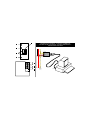
-12V+ BUS
TWISTED
PAIR
(0.5mm )
2
To USB-Port
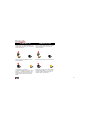
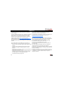
CONNECTION EXAMPLE - AANSLUITVOORBEELD -
EXAMPLES DE CONNEXION - ANSCHLUSSBEISPIELE -
EJEMPLO DE CONEXIÓN
1
2
3
4
6
7
8
5
-
+
L
H

3
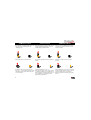
1. Velbus TX (transmit) LED
2. Velbus RX (receive) LED
3. USB status LEDs
4. Velbus power LED
5. Connection to the USB port of the computer
6. 12V power supply
7. Velbus
8. Termination
1. LED TX (transmission) du velbus
2. LED RX (réception) du velbus
3. LED état USB
4. LED d’alimentation du velbus
5. Connexion vers le port USB de l’ordinateur
6. Alimentation 12V
7. Velbus
8. Terminaison
1. LED de transmisión del velbus
2. LED de recepción del velbus
3. LED estado USB
4. LED de alimentación del velbus
5. Conexión al puerto USB del ordenador
6. Alimentación 12V
7. Velbus
8. Terminación
1. Velbus-Sende-LED
2. Velbus- Empfangs-LED
3. USB-Status-LEDs
4. Velbus Stromversorgungs-LED
5. Anschluss zum USB-Port des Computers
6. 12V-Stromversorgung
7. Velbus
8. Abschlusswiderstand
1. Velbus TX (zend) LED
2. Velbus RX (ontvang) LED
3. USB status-LED
4. Velbus voedings-LED
5. Verbinding naar de USB-poort van de computer
6. 12V voeding
7. Velbus
8. Afsluiting
UK
NL
FR
D
ES

4
TERMINATION AFSLUITING TERMINAISON
If the module is connected at the start or end
of a cable on the VELBUS, place the
‘TERM’ jumper.
Remove the jumper in all other cases.
If different cable wiring topologies (tree,
star, loop, ...) are used, place a jumper on the
end module of the longest cable only, NOT
on each end point.
Indien de module op het begin of het einde van
de VELBUS-kabel aangesloten is, moet de
‘TERM’ jumper geplaatst worden.
In alle andere gevallen moet deze verwijderd
worden.
Indien de bekabeling in ster- of
boomstructuur uitgevoerd is, wordt er enkel
een afsluiter geplaatst op de module die aan
het beginpunt van de kabel aangesloten is en
op de module die op het uiteinde van de
langste kabel aangesloten is.
Placez le cavalier TERM uniquement dans
un module connecté au début ou en fin de
connexion Velbus.
Effacez le cavalier dans tous les autres
modules.
Placez uniquement un cavalier sur le dernier
module du câble le PLUS LONG et non sur
tous les modules lorsque vous utilisez
différents modèles de câblage (arbre, étoile
boucle…).

5
Montieren Sie die TERM-Steckbrücke bei
einem Modul am Anfang oder am Ende des
Velbus-Anschlusses.
Entfernen Sie die Steckbrücke bei allen
anderen Modulen.
Verwenden Sie verschiedene
Verdrahtungsausführungen (Baum, Stern,
Schleife…), verbinden Sie dann nur eine
Steckbrücke mit dem letzten Modul des
längsten Kabels und NICHT mit jedem
Modul
VERSCHLUSS
Ponga el jumper TERM sólo en un módulo
conectada al principio o al extremo de
conexión Velbus.
Borre el jumper en todos los otros módulos.
Ponga sólo un jumper en el último módulo
del cable MÁS LARGO y no en todos los
módulos si utiliza diferentes modelos de
cableado (árbol, estrella, bucle…).
TERMINACIÓN

6
CONNECTION
For connection between the modules, use twisted pair cable (ex.
EIB 2x2x0.8mm2, UTP 8x0.51mm - CAT5 or other). Use mini-
mum 0.5mm² cable. For long wiring (>50m) or if a lot of modules
( > 10) are connected to one wire, use 1mm² cable. Connect the 12-
18Vdc (mind the polarity) and connect the bus wires (mind the
polarity).
Connect the module with a USB port on the computer. You can us
one of the following Velleman USB cable types: CW076, CW077,
CW078, CW090A, CW090B or CW090C.
Remark:
The USB computer connection is galvanically separated from the
VELBUS and the 12V power cable via an optical link.
If the module is connected as the final device on the VELBUS, place
the ‘TERM’ jumper. Remove the jumper in all other cases.
Om de modules met elkaar te verbinden gebruikt men best een
twisted-pair kabel (EIB 2x2x0.8mm2, UTP 8x0.51mm - CAT5 of
gelijkwaardig). Indien er veel modules (meer dan 10) op de kabel
aangesloten zijn of bij zeer lange leidingen (langer dan 50m) is het
belangrijk om de draaddoorsnede voldoende dik te voorzien
(0.5mm2 of meer). Verbind de 12V tot 18V gelijkspanning (let op
de polariteit) met de module. Sluit de bus aan (let op de polariteit)
op de module.
Verbind de module met een USB-poort van de computer. U kan
hiervoor één van de volgende USB kabeltypes van Velleman
gebruiken: CW076, CW077, CW078, CW090A, CW090B of
CW090C.
Opmerking:
De USB computerverbinding is galvanisch gescheiden van de
VELBUS en de 12V voedingskabel via een optische link.
Indien de module als laatste op de VELBUS aangesloten is, moet de
‘TERM’ jumper geplaatst worden. In alle andere gevallen moet deze
verwijderd worden.
AANSLUITING

7
CONNEXION
Utilisez un câble torsadé (UTP ou autre) pour interconnecter les
modules. Utilisez un câble avec un diamètre minimal de 0.5mm².
Utilisez un câble avec un diamètre de 1mm² pour les longues
connexions (> 50m) ou lorsque la connexion comporte une
multitude élevée de modules (> 10).
Connectez le 12-18VCC (respectez la polarité) et le câblage du bus
(respectez la polarité).
Connectez le module au port USB de votre ordinateur. Pour ceci,
utilisez un type de câble USB de la marque Velleman : CW076,
CW077, CW078, CW090A, CW090B ou CW090C.
Remarque:
La connexion USB est galvaniquement séparée du VELBUS et
l’alimentation 12V par un lien optique.
Si le module est connecté comme dernier appareil dans la série
VELBUS, il faut placer le pontage ‘TERM’. Retirez-le si ceci n’est
pas le cas.
Verbinden Sie die 12V bis 18V Gleichspannung (achten Sie auf die
Polarität) mit dem Modul. Bei sehr langen Leitungen ist es wichtig,
dass der Drahtdurchmesser ausreichend dick ist (1mm2). Schließen
Sie den Bus an das Modul an (achten Sie auf die Polarität).
Verwenden Sie dazu eine verdrillte Leitung mit einem
Durchmesser von 0.5mm2 oder mehr bei sehr langen Leitungen.
Verbinden Sie das Modul mit einem USB-Port des Computers. Sie
können dazu einen der folgenden USB-Kabeltypen von Velleman
verwenden: CW076, CW077, CW078, CW090A, CW090B oder
CW090C.
Bemerkung:
Die USB Computerverbindung ist galvanisch vom
VELBUS getrennt und dem 12V-Stromversorgungskabel getrennt
über einen optischen Link.
Wenn das Modul als letztes an das VELBUS-System
angeschlossen ist, muss der ‘TERM’ Jumper installiert werden. In
allen anderen Fällen soll er entfernt werden.
ANSCHLUSS

8
Utilice un cable trenzado (EIB 2x2x0.8mm2, UTP 8x0.51mm -
CAT5 u otro) para interconectar los módulos. Utilice un cable con
un diámetro mín. de 0.5mm². Utilice un cable con un diámetro de
1mm² para conexiones largas (> 50m) o si están conectados
muchos módulos (> 10) a un cable. Conecte 12-18VDC (respete la
polaridad) y el cableado del bus (respete la polaridad).
Conecte el módulo al puerto USB del ordenador. Utilice un cable
USB de la marca Velleman: CW076, CW077, CW078, CW090A,
CW090B o CW090C.
Nota:
La conexión USB está separada de manera galvánica del VELBUS
y el cable de alimentación 12V por una conexión óptica.
Si el módulo está conectado como último aparato en la serie
VELBUS, ponga el puente ‘TERM’. Quítelo si no es el caso.
CONEXIÓN

USE - GEBRUIK - EMPLOI - ANWENDUNG - USO

10
Connect the module to the VELBUS system and the computer
(see connection diagram).
At the first connection of the module with a computer without
the driver, the upper USB status LED will blink. The computer
operating system detects new hardware and will ask to localize
and to install the driver (.inf file).
This file can be downloaded from www.velleman.be/
download/files/
After the installation of the driver, both LEDs will alternately
blink as an indication that communication is established.
In case of a different LED status, the interface will be in one
of following situations:
Both LEDs are turned off when the USB cable is not con-
nected.
Both LEDs turn on when the USB cable is connected but
the interface module is not powered.
Only the upper LED turns on when the interface is powered
but not reset.
Only the lower LED turns on when the interface is powered
and reset but has no attributed address.
The LEDs blink very rapidly at too high USB power con-
sumption.
Software to use with this interface or information to develop
your own software can be downloaded from
www.velleman.be/download/files/
At power-on, the module will send a ‘Bus active’- and a
‘Reception ready’-message to the computer.
All messages appearing onto the VELBUS system will also be
forwarded to the computer.
Valid commands generated by the computer are forwarded to
the module via the USB port.
These commands are placed onto the VELBUS system by the
USB interface module.
When too many commands are sent simultaneously, the recep-
tion buffer will overflow. This will be reported to the com-
puter. The computer program must break off the communica-
tion and wait for the ‘reception ready’ message before sending
new commands.
If the commands are incorrectly placed onto the VELBUS, a
bus error will occur and will also be forwarded to the com-
puter. The USB interface module will auto-restart after 25
seconds and erase the reception buffer.
USE

11
Verbind de module met het VELBUS-systeem en de computer
(zie aansluiting). Wanneer de module voor de eerste maal met
een computer verbonden wordt waarop de driver nog niet
geïnstalleerd is, zal de bovenste USB status-LED knipperen.
Het besturingssysteem van de computer detecteert nieuwe
hardware en vraagt om de driver (.inf bestand) te lokalizeren
en te installeren. Dit bestand kan men downloaden van de
website www.velleman.be/download/files/
Eenmaal de driver correct geïnstalleerd is, zullen de beide
LEDs afwisselend knipperen ter indicatie dat er
gecommuniceerd kan worden.
Is de toestand van de status LEDs verschillend aan
bovenstaande gevallen dan bevindt de interface zich in één
van de volgende toestanden:
Beide LEDs zijn uit als de USB-kabel niet verbonden is.
Beide LEDs lichten op als de USB-kabel verbonden is maar
de interface module niet gevoed wordt.
Alleen de bovenste LED licht op indien de interface gevoed
maar niet gereset wordt.
Enkel de onderste LED licht op wanneer de interface wel
gevoed, gereset maar geen uniek adres toegekend werd.
De LEDs knipperen zeer snel bij een te hoog
stroomverbruik.
GEBRUIK
Op de computer moet men een programma draaien dat toelaat
met het VELBUS-systeem te communiceren.
Dit programma of informatie om zelf een programma te
ontwikkelen kan men downloaden van de website
www.velleman.be/download/files/
Bij het onder spanning komen van de module wordt een ‘Bus
actief’ en ‘Ontvangst klaar’ boodschap naar de computer
verstuurd.
Alle boodschappen die nu op het VELBUS-systeem
verschijnen, worden eveneens verstuurd naar de computer.
Geldige commando’s gegenereerd door de computer worden
via de USB-poort naar de module verstuurd.
Deze commando’s worden door de USB-interface module op
het VELBUS-systeem geplaatst.
Indien er teveel commando’s ineens verstuurd worden, zal de
ontvangstbuffer vol lopen en wordt dit gemeld aan de
computer. Het computerprogramma moet nu het verzenden
onderbreken en wachten op een ‘ontvangst klaar’ bericht om
terug nieuwe commando’s te kunnen aanbieden.
Als de commando’s niet correct op de VELBUS geplaatst
kunnen worden, zal er een busfout optreden en doorgegeven
worden naar de computer. Na 25 seconden zal de USB-
interface module zichzelf herstarten en de ontvangstbuffer
wissen.

12
Connectez le module au système VELBUS et l’ordinateur
(voir le câblage).
Lors de la première connexion avec un ordinateur sur lequel le
pilote n‘est pas encore installé, la LED d’état de l’USB du
haut clignotera. Le système d’exploitation de l’ordinateur
détecte un nouveau périphérique et demande à localiser et à
installer le pilote (le fichier .inf). Ce fichier peut être
téléchargé à partir du site www.velleman.be/download/files/
Une fois le pilote correctement installé, les deux LEDs
clignoteront alternativement pour indiquer une communication
possible.
Si l’état des LEDs ne correspondent pas au cas décrits ci-
dessus, l’interface se trouvera dans un des modes suivants :
Les deux LEDs sont éteintes lorsque le câble USB n’est pas
connecté.
Les deux LEDs sont allumées lorsque le câble USB est
connecté mais lorsque le module d’interface n’est pas
alimenté.
Uniquement la LED du haut s’allume lorsque l’interface est
alimentée mais pas remise à zéro.
Uniquement la LED du bas s’allume lorsque l’interface est
connectée, remise à zéro mais n’ap pas d’adresse unique.
Les LEDs clignotent très rapidement lors d’une
consommation USB trop importante.
Exécutez un programme sur l’ordinateur permettant la
communication avec le système VELBUS.
Ce programme ou l’information nécessaire pour développer le
programme peuvent être téléchargés à partir du site
www.velleman.be/download/files/.
Lors de la mise sous tension du module, des messages ‘Bus
actif’ et ‘Prêt pour la réception’ sont envoyés vers l’ordinateur.
Tous les messages apparaissant sur le système VELBUS
seront également envoyés vers l’ordinateur.
Les commandes valides générées par l’ordinateur seront
envoyées vers le module depuis le port USB.
Ces commandes sont placées sur la système VELBUS par
l’interface USB.
Lors d’un surplus de commandes envoyées, le tampon de
réception sera saturé. Cette saturation sera notifiée à
l’ordinateur. Le programme interrompt le transfert et attend un
message ‘Prêt pour la réception’ avant de pouvoir présenter de
nouvelles commandes.
Lorsque les commandes ne sont pas correctement placées sur
le VELBUS, une erreur bus apparaîtra et celle-ci sera envoyée
à l’ordinateur. L’interface USB se rétablira et effacera le
tampon de réception.
EMPLOI

13
Verbinden Sie das Modul mit dem VELBUS-System und dem
Computer (siehe Anschlüsse). Wenn das Modul zum ersten Mal mit
einem Computer verbunden wird, auf dem der Treiber noch nicht
installiert ist, wird die obere USB-Status-LED blinken. Das
Betriebssystem des Computers detektiert die neue Hardware und
bittet darum, den Treiber (inf. Datei) zu lokalisieren und
installieren. Sie können diese Datei von unserer Website
www.velleman.be/download/files/ herunterladen.
Wenn der Treiber korrekt installiert ist, werden die beiden LEDs
abwechselnd blinken, als Anzeige, dass kommuniziert werden
kann.
Wenn der Zustand der Status-LEDs gegenüber den oben erwähnten
Fällen unterschiedlich ist, dann befindet sich die Schnittstelle in
einer der folgenden Lagen:
Beide LEDs sind aus wenn das USB-Kabel nicht verbunden ist.
Beide LEDs leuchten auf wenn das USB-Kabel verbunden ist,
aber das Schnittstellenmodul nicht mit Strom versorgt wird.
Nur die obere LED leuchtet auf wenn die Schnittstelle mit Strom
versorgt, aber nicht rückgesetzt wird.
Nur die untere LED leuchtet auf wenn die Schnittstelle mit
Strom versorgt und zurückgesetzt wurde, aber keine einzigartige
Adresse zugewiesen wurde.
Die LEDs blinken sehr schnell bei einem zu hohen
Stromverbrauch.
Auf dem Computer sollte man ein Programm, das ermöglicht,
mit dem VELBUS-System zu kommunizieren, laufen lassen.
Dieses Programm oder Informationen um ein solches
Programm zu schreiben, können sie von der Website
www.velleman.be/download/files/ herunterladen.
Beim unter Spannung setzen des Moduls wird die ‘Bus aktiv’
und ‘Empfang fertig’ Meldung an den Computer geschickt.
Alle Mitteilungen die jetzt auf dem VELBUS-System
erscheinen werden auch an den Computer geschickt.
Gültige Befehle von dem Computer generiert werden über den
USB-Port an das Modul geschickt.
Diese Befehle werden von der USB-Schnittstelle auf das
VELBUS-System gesetzt.
Wenn zuviele Befehle auf einmal verschickt werden, wird der
Empfangspuffer voll geraten und wird das an den Computer
gemeldet. Das Computerprogramm muss jetzt das Versenden
unterbrechen und auf eine 'Empfang fertig'-Mitteilung warten
um erneut neue Befehle anbieten zu können.
Wenn die Befehle nicht korrekt auf VELBUS gesetzt werden
können, dann wird ein Busfehler auftreten und wird diesen an
den Computer gemeldet werden. Nach 25 Sekunden wird die
USB-Schnittstelle sich erneut starten und den Empfangspuffer
löschen.
ANWENDUNG

14
Conecte el módulo al sistema VELBUS y al ordenador (véase el
cableado).
Al conectar el módulo por primera vez a un ordenador que
todavía no está equipado con el driver, el LED de estado superior
USB parpadeará. El sistema operativo del ordenador detecta
nuevo hardware y pide que localice e instale el driver (el
fichero .inf). Es posible descargar este fichero de la página web
www.velleman.be/download/files/
Después de haber instalado el driver correctamente, los dos LEDs
parpadearán alternativamente para indicar una comunicación
posible.
Si el estado de los LEDs no coincide con los casos descritos
arriba, el interface estará en uno de los siguientes modos:
Los dos LEDs están apagados si el cable USB no está
conectado.
Los dos LEDs están encendidos si el cable USB está conectado
pero si el módulo interface no está alimentado.
Sólo el LED superior se ilumina si el interface está alimentado
pero no reinicializado.
Sólo el LED inferior se ilumina si el interface está conectado,
reinicializado pero no tiene una dirección única.
Los LEDs parpadean muy rápidamente si hay un consumo
demasiado alto.
Utilice un programa en el ordenador que permite comunicar
con el sistema VELBUS.
Es posible descargar este programa o la información necesaria
para desenrollar el programa de la página web
www.velleman.be/download/files/.
Al activar el módulo, los mensajes ‘Bus actif’ y ‘Listo para la
recepción’ se envían al ordenador.
Todos los mensajes que aparecen en el sistema VELBUS se
enviarán también al ordenador.
Los órdenes válidos generados por el ordenador se enviarán al
módulo desde el puerto USB.
Estos órdenes se ponen en el sistema VELBUS por el interface
USB.
Si se envían demasiados órdenes a la vez, la memoria tapón de
recepción se saturará y esto se comunicará al ordenador. El
programa interrumpe la transmisión y espera el mensaje ‘listo
para la recepción’ antes de poder ofrecer nuevos órdenes.
Si no se ponen los órdenes correctamente en el VELBUS, un
error bus aparecerá y se enviará al ordenador. La interface
USB se restablecerá y borrará la memoria tapón de recepción.
USO


VELLEMAN Components NV
Legen Heirweg 33
9890 Gavere
Belgium Europe
www.velleman.be
www.velleman-kit.com
www.velbus.be
Modifications and typographical errors reserved - © Velleman Components nv.
HVMB1USB - 2007 - ED1
5 410329 359867
-
 1
1
-
 2
2
-
 3
3
-
 4
4
-
 5
5
-
 6
6
-
 7
7
-
 8
8
-
 9
9
-
 10
10
-
 11
11
-
 12
12
-
 13
13
-
 14
14
-
 15
15
-
 16
16


in anderen Sprachen
- français: Velleman VMB1USB Guide d'installation
- español: Velleman VMB1USB Guía de instalación
- Nederlands: Velleman VMB1USB Installatie gids
Verwandte Artikel
Andere Dokumente
-
Nvidia nForce 570 SLI Benutzerhandbuch
-
ASROCK 880G Pro3 Bedienungsanleitung
-
MSI MEG Z590 ACE GOLD EDITION Bedienungsanleitung
-
MSI MEG Z590 UNIFY Bedienungsanleitung
-
-
MSI X370 XPOWER GAMING TITANIUM Bedienungsanleitung
-
ASROCK 4CORE1600TWINS-P35D Bedienungsanleitung
-
-
MSI 7C71 2.0 Bedienungsanleitung