WIKA WUC-10 tag:model:WUC-15 tag:model:WUC-16 Bedienungsanleitung
- Typ
- Bedienungsanleitung

Operating instructions
Betriebsanleitung
WIKA Alexander Wiegand SE & Co. KG
Alexander-Wiegand-Straße 30
63911 Klingenberg
/Germany
Phone +49 9372 132-0
Fax +49 9372 132-406
www.wika.de
11384850.09 EN/DE 02/2019
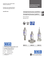
Ultra High Purity Transducer, model WUC-1x
Version Standard
Version Ex nA ic
WUC-15WUC-10
WUC-16
Current terms and conditions apply.
Details are available on ...
Es gelten unsere aktuellen Verkaufs-
und Lieferbedingungen siehe unter ...
www.wika.com
EN
Ultra High Purity Transducer, Typ WUC-1x DE

EN
DE
11384850.09 EN/DE 02/2019
2
WIKA Operating instructions / Betriebsanleitung, WUC-1x
Operating instructions model WUC-1x Page 3 - 22
Betriebsanleitung Typ WUC-1x Seite 23 - 44
© 2009 WIKA Alexander Wiegand SE & Co. KG
All rights reserved. / Alle Rechte vorbehalten.
WIKA
®
is a registered trademark in various countries.
WIKA
®
ist eine geschützte Marke in verschiedenen Ländern.
Prior to starting any work, read the operating instructions!
Keep for later use!
Vor Beginn aller Arbeiten Betriebsanleitung lesen!
Zum späteren Gebrauch aufbewahren!

11384850.09 EN/DE 02/2019
WIKA Operating instructions / Betriebsanleitung WUC-1x
3
Contents
1. Important details for your information 4
2. A quick overview for you 5
3. Signs, symbols and abbreviations 5
4. Function 6
5. For your safety 6
6. Packaging 7
7. Starting, operation 8
8. Adjustment of zero point 18
9. Maintenance, accessories 19
10. Trouble shooting 19
11. Storage, disposal 21
12. EU Declaration of conformity 42
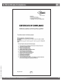
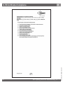
13. FM Certicate of compliance 43
14. Control drawing (FM) 47
Contents
EN

11384850.09 EN/DE 02/2019
4
WIKA Operating instructions / Betriebsanleitung, WUC-1x
1. Important details for your information EN
Read these operating instructions without fail before installing and starting the pressure transmitter.
1. Important details for your information
Read these operating instructions before installing and starting the pressure transmitter. Keep the operating instructions in a
place that is accessible to all users at any time.
The following installation and operating instructions have been compiled by us with great care but it is not feasible to take
all possible applications into consideration. These installation and operation instructions should meet the needs of most
pressure measurement applications. If questions remain regarding a specic application, you can obtain further information:
■
Via our Internet address www.wika.de / www.wika.com
■
The product data sheet is designated as PE 87.06
■
Contact WIKA for additional technical support +49 9372 132-0
If the serial number on the product label gets illegible (e.g. by mechanical damage or repainting), the retraceability of the
instrument is not possible any more.
WIKA transducers are carefully designed and manufactured using state-of-the-art technology. Every component under-
goes strict quality and environmental inspection before assembly and each instrument is fully tested prior to shipment. Our
environmental management system is certied to DIN EN ISO 14001.
Use of the product in accordance with the intended use WUC-10, WUC-15 and WUC-16:
Use the transducer to transform the pressure into an electrical signal.
For transducer with Ex-marking:
Use the nonincendive transducer of category 3G to transform the pressure into an electrical signal in hazardous areas of zone 2.
Certicate for transducer with Ex and IECEx marking:
Transducer for operation in hazardous areas.
ATEX marking: II 3 G Ex nA ic IIC T6/T5/T4 Gc X
IECEx marking: IECEx BVS 13.0070 X, Ex nA ic IIC T6/T5/T4 Gc
Certicate for transducer with FM marking:
Transducer for operation in hazardous areas in compliance with the respective certicate (see Control drawing No.
11374595, page 44).
FM Approval ratings: Non-incendive for Class I Division 2 Groups A, B, C and D

11384850.09 EN/DE 02/2019
WIKA Operating instructions / Betriebsanleitung WUC-1x
5
WARNING!
Potential danger of life or of severe injuries.
WARNING!
For transducer with Ex-marking: Instructions for
hazardous areas: Potential danger of life or of
severe injuries.
Information
Notice, important information, malfunction.
For transducer with FM (Factory Mutual)
marking
The product was tested and certied by FM
Approvals. It complies with the applicable
US-American standards on safety (including
explosion protection).
V DC Direct voltage
1. ... / 2. A quick overview for you / 3. Signs and symbols EN
Knowledge required: Install and start the transducer only if you are familiar with the relevant regulations and directives of
your country and if you have the qualication required. You have to be acquainted with the rules and regulations on hazard-
ous areas (if transducer with Ex-marking), measurement and control technology and electric circuits, since this transducer
is „electrical equipment“ as dened by EN 60079-14. Depending on the operating conditions of your application you have to
have the corresponding knowledge, e.g. of aggressive media.
2. A quick overview for you
If you want to get a quick overview, read Chapters 3, 5, 7 and 11. There you will get some short safety instructions and
important information on your product and its starting. Read these chapters in any case.
3. Signs, symbols and abbreviations
WARNING!
Potential danger of life or of severe injuries due
to catapulting parts.
CAUTION!
Potential danger of burns due to hot surfaces.
The product complies with the applicable
European directives.
For transducer with Ex-marking
ATEX European guideline for explosion protec-
tion. The product complies with the requirements
of the European directive 2014/34/EU (ATEX) on
explosion protection.

11384850.09 EN/DE 02/2019
6
WIKA Operating instructions / Betriebsanleitung, WUC-1x
3. Signs and symbols / 4. Function and accessories / 5. For your safety EN
2-wire Two connection lines are intended for the voltage supply.
The supply current is the measurement signal.
3-wire Two connection lines are intended for the voltage supply.
One connection line is intended for the measurement signal.
U+ Positive supply connection
U- Negative supply connection
S+ Positive measurement connection
4. Function
Ultra High Purity Transducer
WUC-10: Single End
WUC-15: Flow Through
WUC-16: Modular Surface Mount
Function: The pressure prevailing within the application is transformed into a standardised electrical signal through the
deection of the diaphragm, which acts on the sensor element with the power supply fed to the transmitter. This electric
signal changes in proportion to the pressure and can be evaluated correspondingly
5. For your safety
WARNING!
■
Select the appropriate transducer with regard to scale range, performance and specic measurement condi-
tions prior to installing and starting the instrument.
■
Consider the relevant national regulations (e.g.: EN/IEC 60079-14) and observe the applicable standards and
directives for special applications (e.g. with dangerous media such as acetylene, ammable gases or liquids
and toxic gases or liquids and with compressors). If you do not observe the appropriate regulations, serious
injuries and/or damage can occur!
■
Open pressure connections only after the system is without pressure!
■
Please make sure that the transducer is only used within the overload threshold limit all the time!
■
Observe the ambient and working conditions outlined in section 7 „Technical data”.
■
Ensure that the transducer is only operated in accordance with the provisions i.e. as described in the following
instructions.
■
Do not interfere with or change the transducer in any other way than described in these operating instructions.

11384850.09 EN/DE 02/2019
WIKA Operating instructions / Betriebsanleitung WUC-1x
7
5. For your safety / 6. Packaging EN
WARNING!
■
Remove the pressure transmitter from service and mark it to prevent it from being used again accidentally, if it
becomes damaged or unsafe for operation
■
Take precautions with regard to remaining media in removed pressure transmitter. Remaining media in the
pressure port may be hazardous or toxic!
■
Have repairs performed by the manufacturer only.
■
The operator is responsible for the material compatibility as well as correct handling, operation and mainte-
nance.
Information about material consistency against corrosion and diusion can be found in our WIKA-Handbook, 'Pressure and
Temperature Measurement'.
WARNING!
For transducer with Ex-/FM-marking: Consider the relevant safety instructions as well as the respective country
specic regulations for installation and operation in hazardous areas (e.g.: IEC 60079-14, NEC). If you do not
observe these stipulations, serious injuries and/or damage may occur.
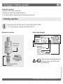
6. Packaging
Has everything been supplied?
Check the scope of supply:
■
Completely assembled transducer
■
Inspect the transducer for possible damage during transportation. Should there be any obvious damage, inform the trans-
port company and WIKA without delay.
■
The UHP transducers are puried, evacuated and double-packed in clean rooms in a protective atmosphere (clean room
class 5 according to ISO 14644). Special plastic protective caps are used to protect the high-quality threaded connections
(ttings). The gauges should remain in this special packaging until installation in order to prevent damage and contamina-
tion. Therefore remove the ESD (Electro-Static-Discharge) protective foil only at the place of installation.
■
Keep the packaging, as it oers optimal protection during transportation (e.g. changing installation location, shipment for
repair).
■
Ensure that the pressure connection thread and the connection contacts will not be damaged.
■
Remove this protection cap only just before installing the transducer.
■
Mount the protection cap when removing and transporting the instrument.

11384850.09 EN/DE 02/2019
8
WIKA Operating instructions / Betriebsanleitung, WUC-1x
6. Packaging / 7. Starting, operation EN
Unpack the transducer
1. Remove the transducer from the box.
2. Remove the outer protective bag and discard.
3. Carry the transducer (sealed in the inner bag), into the clean area.
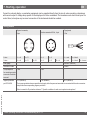
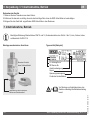
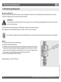
7. Starting, operation
Required tools: wrench (ats 19 and 16), screw driver (0.040" to 0.060" /
1 to 1.5 mm) and a pair of scissors, allen key for WUC-16
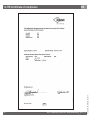
Mechanical connection Product label (example)
Product No.
Serial No.
PIN assignment
Signal
Power Supply
Coded manufacture date
S #
P #
Use this wrench at for
screwing in!
Don't use this
wrench at!
Before mounting and commissioning the
instrument, ensure you read the opera-
ting instructions!

11384850.09 EN/DE 02/2019
WIKA Operating instructions / Betriebsanleitung WUC-1x
9
7. Starting, operation EN
■
Remove the protection cap only just before installation.
■
When mounting the instrument, ensure that the sealing faces of the instrument and the measuring point are
clean and undamaged.
■
Do not scratch or nick the bead. Do not over tighten. Damage to the bead will aect the tting's performance
and may cause leakage in the system.
■
Screw in or unscrew the instrument only via the ats using a suitable tool and the prescribed torque. The
appropriate torque depends on the dimension of the pressure connection and on the sealing element used
(form/material). Do not use the case as working surface for screwing in or unscrewing the instrument.
■
When screwing the transmitter in, ensure that the threads are not jammed.
WARNING!
For transducer with Ex-/FM-marking:
■
Protect the inner diaphragm against any contact with abrasive substances and pressure peaks and do not
touch it with tools. Damage of the diaphragm may result in losing the explosion protection.
■
Observe the technical data for the use of the transducer in connection with aggressive / corrosive media and
for the avoidance of mechanical hazards.
Mechanical Connection
■
Prepare the gas line connections appropriately.
■
You should blow clean all tting components (such as sealing gaskets, for example) using a clean/ltered gas. Please
refer to the specic technical guides furnished by the gasket manufacturers for additional specications.
■
You can then remove the protective lm, as well as any plastic caps there may be for protecting high-quality ttings.
Face Seal Connections (only WUC-10, WUC-15)
For connections compatible with VCR
®
-ttings:
1. Hold the swivel female face seal / swivel male face seal, mounting part (valve etc.) or case hexagon. Tighten the swivel
female face seal hand-tight and adjust the instrument to the desired position. When tightening or untightening at mounting
parts (valves etc.) or ttings, ensure that the threads do not get jammed.
2. Hold the swivel female face seal with a suitable open-end wrench. Tighten the swivel female face seal / swivel male face
seal or mounting part (valve etc.) by a 1/8 or 1/4 turn (depending on the sealing elements used) beyond the hand-tight
position.
3. Please refer to the specic technical guides furnished by the tting manufacturers for additional specications.
4. With that the transducer is mechanically connected. Electrical connection possibilities are described in the following
section.

11384850.09 EN/DE 02/2019
10
WIKA Operating instructions / Betriebsanleitung, WUC-1x
7. Starting, operation EN
Welding Connections (only WUC-10, WUC-15)
The weld needs to be fully penetrating, but amperage and heat need to be minimised. We recommend owing Argon gas
through the transducer during welding. This will help to cool the transducer. Prior to welding tubing to the transducer, it is
recommended that a few test welds be made.
WARNING!
■
Make sure the transducer is not connected to any other device, prior to arc welding.
■
Disconnect the transducer from any electrical device.
■
The operator is responsible for the material compatibility as well as correct handling, operation and mainte-
nance.
Prepare the transducer for use
1. Adjust the zero point (please refer to chapter Zero Adjustment).
2. Verify integrity of the weld or seal by appropriate helium leak-testing procedures.
3. Turn the gas ow ON then OFF, 10 times to remove any particles generated during installation. (The ow rate used should
at least equal the process ow specications.)
MSM, Modular Surface Mount (only WUC-16)
Please observe the corresponding technical specications, such as torques and mounting position of the contact compo-
nents.

11384850.09 EN/DE 02/2019
WIKA Operating instructions / Betriebsanleitung WUC-1x
11
Electrical connection
WARNING!
Connect the enclosure to ground through the process connection, against electromagnetic elds and electro-
static discharge.
WARNING!
Specic conditions for safe use in explosive atmosphere
■
External earthing connection shall be established by end-user via pressure connection minimum 4 mm²
required. External earthing connection shall be corrosion resist and locked against rotation.
■
The connector provided by the end user in the end use application shall be in accordance with all applicable
clauses of IEC 60079-0 and IEC 60079-15. A minimum degree of protection IP54 according to IEC 60529 shall
be ensured.
■
Cable provided by end-user shall be suitable for the ambient temperature.
■
The Sub-D version has to be installed in a way that it is protected against an impact energy > 4 J. The connec-
tor as well as the corresponding sealing are provided by the end user in the end use application and shall be
in accordance with all applicable clauses of IEC 60079-0 and IEC 60079-15. A minimum degree of protection
IP54 according to IEC 60529 shall be ensured.
■
For use under NEPSI conditions:
- The connector provided by the end user in the end use application shall be in accordance with all applicable
clauses of GB3836.1-2010 and GB3836.8-2003. A minimum degree of protection IP 54 shall be ensured.
- Obey the warning “Do not separate when energized”.
7. Starting, operation EN

11384850.09 EN/DE 02/2019
12
WIKA Operating instructions / Betriebsanleitung, WUC-1x
7. Starting, operation EN
■
If long connecting cables (greater than 30m) or leads outside buildings are to be used, use screened leads.
Note that with plug connectors, no connection between cable screen and housing is possible. Take care, there-
fore, for installations in explosion hazard areas, that equipotential bonding is used.
For instruments with cable outputs, the cable is always shielded. Depending upon the design (ordered version)
the screen may or may not be connected with the enclosure. Also provide for equipotential bonding here, if
necessary.
■
Ensure that the cable diameter you select ts to the cable gland of the connector Ensure that the cable gland of
the mounted connector is positioned correctly and that the sealings are available and undamaged. Tighten the
threaded connection and check the correct position of the sealings in order to ensure the ingress protection
■
Cover ying leads with ne wires by an end splice (cable preparation).
■
Please make sure that the ends of cables with ying leads do not allow any ingress of moisture.
■
The transducer must be connected and operated in accordance with the approriate regulations. Take care to
ensure that the electrical connection (e.g. M12 connector) is correctly made (fully sealed).
WARNING!
■
For equipment with Ex nA ic certication, or if operated under nA ic conditions: Do not separate when
energized.
■
For products with FM Approval: The connection between cable and connector shall withstand a tensile force of
min. 15 N
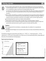
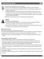
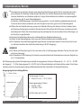
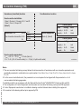
The transducer is designed to operate with an input voltage of 10 ... 30 VDC / 14 ... 30 with output signal 0 ... 10 V. The
voltage value Ui = 30 VDC shall not be exceeded in the current loop circuit. The interrelationship between voltage supply and
load resistor (R
A
) is illustrated by the following diagram.
Signal output and allowed load
4 ... 20 mA, 2-wire
permitted range
Current output (2-wire)
4 ... 20 mA:
R
A
≤ (U+ – 10 V) / 0,02 A
Voltage output (3-wire)
0 ... 5 V: R
A
> 5 kΩ
0 ... 10 V: R
A
> 10 kΩ
with R
A
in Ohm and U+ in Volt

11384850.09 EN/DE 02/2019
WIKA Operating instructions / Betriebsanleitung WUC-1x
13
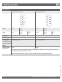
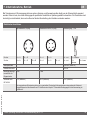
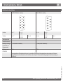
Wiring details
Bayonet connector,
4-pin
Circular connector M12x1, 4-pin
Flying leads,
1.5 m
2-wire U+ = A U- = D U+ = 1 U- = 3 U+ = red U- = black
3-wire U+ = A U- = D S+ = B U+ = 1 U- = 3 S+ = 4 U+ = red U- = black S+ = brown
Wire gauge - - 0.22 mm
2
(AWG 24)
Diameter of cable - - 4.8 mm
Torque required
for mounting counter-
connector should be
ensured:
1 Nm 1 Nm -
Ingress protection
per IEC 60529
IP 67 (NEMA 4) IP 67 (NEMA 4) IP 67 (NEMA 4)
The ingress protection classes specied only apply while the pressure transmitter is connected with female connectors
that provide the corresponding ingress protection.
Refer to remark for IP-protection at clause 7 “Specic conditions for safe use in explosive atmosphere”
7. Starting, operation EN
Current for external display- or evaluation equipment can be supplied directly from the circuit, when operating a transducer
with current output. A voltage drop specic to the display unit is to be considered. The transducers are short-circuit-proof for
a short time, but anyhow any incorrect connection of the instrument should be avoided.
4
3
1
2

11384850.09 EN/DE 02/2019
14
WIKA Operating instructions / Betriebsanleitung, WUC-1x
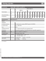
Wiring details
Sub-D HD connector, 15-pin Sub-D connector, 9-pin
2-wire U+ = 7 U- = 5
U-
= 12
U+ = 4 U- = 8
U- = 9
3-wire U+ = 7 U- = 5
U-
= 12
S+ = 2 U+ = 4 U- = 8
U- = 9
S+ = 1
Wire gauge - -
Diameter of cable - -
Torque required
for mounting counter-
connector should be
ensured:
0.3 Nm (both screws) 0.3 Nm (both screws)
Ingress protection
per IEC 60529
IP 54 IP 54
The ingress protection classes specied only apply while the pressure transmitter is connected with female connectors
that provide the corresponding ingress protection.
Refer to remark for IP-protection at clause 7 “Specic conditions for safe use in explosive atmosphere”
7. Starting, operation
EN

11384850.09 EN/DE 02/2019
WIKA Operating instructions / Betriebsanleitung WUC-1x
15
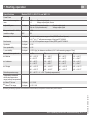
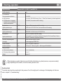
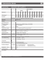
Specications Models WUC-10, WUC-15 and WUC-16
WUC-10 / WUC-15
WUC-16
Pressure ranges psi 30 60 100 160 250 350 500 1000 1500 2000 3000 5000
bar 2 4 7 11 17 25 36 70 100 145 225 360
Over pressure safety
1)
psi 120 120 210 320 500 750 1100 2100 3000 4200 6600 10000
Burst pressure
1)
psi 1800 1800 2200 2600 4800 6200 7400 8000 10500 10500 10500 10500
Other pressure ranges and pressure units (e.g. MPa, kg/cm
2
) on request
Measuring principle Metal thin-lm sensor
Materials
Wetted parts
■
Pressure connection 316L stainless steel, according to SEMI F20 (option: 316L VIM/VAR)
■
Pressure sensor 2.4711 / UNS R30003
Case 304 SS
Inboard helium leak test < 1 x 10
-9
mbar l/sec (atm STD cc/sec) according to Semi F1
Surface nish Electropolished, average Ra ≤ 0.13 µm (RA 5); max. Ra ≤ 0.18 µm (RA 7) per Semi F19
Dead volume cm
3
WUC-10 < 1.5, WUC-15 < 1, WUC-16 < 1
Permissible Medium Specialty gases, vapors, liquids
Power supply U+ U+ in VDC 10 ... 30 with output signal 4 ... 20 mA / 0 ... 5 V
14 ... 30 with output signal 0 ... 10 V
Signal output and maximum
ohmic load R
A
R
A
in Ohm 4 … 20 mA, 2-wire R
A
≤ (U+ – 10 V) / 0.02 A
0 ... 5 V, 3-wire R
A
> 5 k
0 ... 10 V, 3-wire R
A
> 10 k
1) 1 psi = 0.069 bar
7. Starting, operation
EN

11384850.09 EN/DE 02/2019
16
WIKA Operating instructions / Betriebsanleitung, WUC-1x
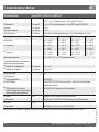
Specications Models WUC-10, WUC-15 and WUC-16
Power Pmax W 1
Max. current consumption
Imax
mA < 30 Current output signal
< 8 Voltage output signal; Source
Adjustability zero % of span -5 up to +3.5 (via potentiometer) Current output signal
-2 up to +5 (via potentiometer) Voltage output signal
Response time (10 ... 90 %) ms ≤ 300
Insulation voltage VDC 500
Accuracy % of span ≤ 0.2 (≤ 0.4 with pressure ranges ≤ 2 bar) RSS (Root Sum Squares)
≤ 0.5
2)
(≤ 1.0
2)
with pressure ranges ≤ 2 bar) per IEC 61298-2
Non-linearity % of span ≤ 0.1 (≤ 0.15 for pressure ranges ≤ 2 bar) (BFSL) per IEC 61298-2
Hysteresis % of span ≤ 0.14
Non-repeatability % of span ≤ 0.12
1-year stability % of span ≤ 0.25% (typ.) at reference conditions (≤ 0.4 % with measuring ranges ≤ 2 bar)
Permissible temperature of non-Ex T4 T5 T6
■
Medium -20 ... +100 °C
-4 ... +212 °F
-20 ... +85 °C
-4 ... +185 °F
-20 ... +60 °C
-4 ... +140 °F
-20 ... +40 °C
-4 ... +104 °F
■
Ambience -20 ... +85 °C
-4 ... +185 °F
-20 ... +85 °C
-4 ... +185 °F
-20 ... +60 °C
-4 ... +140 °F
-20 ... +40 °C
-4 ... +104 °F
■
Storage -40 ... +100 °C
-40 ... +212 °F
-40 ... +100 °C
-40 ... +212 °F
-40 ... +100 °C
-40 ... +212 °F
-40 ... +100 °C
-40 ... +212 °F
Rated temperature range -20 ... +80 °C / -4 ... +176 °F (actively compensated)
Temperature coecients
within rated temperature
range (actively compensated)
■
Mean TC of zero % of span ≤ 0.1 / 10 K
■
Mean TC of range % of span ≤ 0.15 / 10 K
2) Including non-linearity, hysteresis, zero oset and end value deviation (corresponds to measured error per IEC 61298-2)
7. Starting, operation
EN

11384850.09 EN/DE 02/2019
WIKA Operating instructions / Betriebsanleitung WUC-1x
17
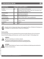
Specications Models WUC-10, WUC-15 and WUC-16
RoHS-conformity Yes
CE- conformitiy
Pressure equipment directive
2014/68/EU
■
EMC directive
2014/30/EU, EN 61326 Emission (Group 1, Class B) and Immunity (industrial application)
■
ATEX directive of equipment
intended for use in potentially
explosive atmospheres
2014/34/EU (for transducer with Ex-marking)
Ex-protection ATEX Category 3G (for transducer with Ex-marking)
Ignition protection type II 3G Ex nA ic IIC T6/T5/T4 Gc X (for transducer with Ex-marking)
Ex-protection IECEx
Ignition protection type IECEx BVS 13.0070x, Ex nA ic IIC T6/T5/T4 Gc
Ex-protection FM Class I (for transducer with FM-marking)
Ignition protection type
Nonincendive for use in Class I, Division 2, Groups A, B, C & D, and Class I, Zone 2,
Group IIC, Hazardous (Classied) Locations
Assembly and packing area Clean room class 5 per ISO 14644
Packaging Double bagging per SEMI E49.6
Shock resistance g 500 (1.5 ms) per IEC 60068-2-27
Vibration resistance mm 0.35 mm (10 ... 58 Hz) / 5 g (58.1... 2000 Hz) per IEC 60068-2-6
Wiring protection
■
Short-circuit resistance S+ vs. U- (short time)
■
Reverse polarity protection U+ vs. U-
Weight kg Approx. 0.1
When designing your plant, take into account that the stated values (e.g.burst pressure, over pressure safety)
apply depending on the material, thread and sealing element used.
Functional test
The output signal must be proportional to the pressure. If not, this might point to a damage of the diaphragm. In that case
refer to chapter 10 „Troubleshooting“.
7. Starting, operation EN

11384850.09 EN/DE 02/2019
18
WIKA Operating instructions / Betriebsanleitung, WUC-1x
7. Starting, operation / 8. Adjustment of zero point EN
WARNING!
■
Open pressure connections only after the system is without pressure!
■
Observe the ambient and working conditions outlined in section 7 „Technical data.
■
Please make sure that the transducer is only used within the over load threshold limit at all times!
CAUTION!
When touching the transducer, keep in mind that the surfaces of the instrument components might get hot during
operation.
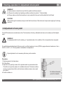
8. Adjustment of zero point
The UHP-Transducers are maintenance free. The transducer is factory calibrated and does not normally need eld adjust-
ment.
WARNING!
For equipment with Ex nA ic marking, or if operated under nA ic conditions: Do not separate when energised.
For verication and adjustment of the zero point, vent the transducer to zero (0)PSI for gage reference transducers. Use a
0.040" to 0.060" (1 to 1.5 mm) jeweler's screwdriver for adjustment.
Span adjustment is not necessary after zero point correction.
Procedure
1. Restore power to the transducer.
2. Lift the sticker.
3. Adjust the zero point by means of the potentiometer in pressureless state.
Check the zero point by means of a suitable instrument. Clockwise rotation
means an upward zero oset, anti-clockwise rotation means a down ward
zero oset.
4. Push the sticker on.
For further information
+49 9372 132-8976

11384850.09 EN/DE 02/2019
WIKA Operating instructions / Betriebsanleitung WUC-1x
19
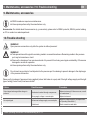
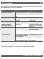
Failure Possible cause Procedure
Output signal unchanged after change in
pressure
Mechanical overload through overpressure
Replace instrument; if failure reoccurs, consult
the manufacturer *)
Wrong supply voltage or current spike Replace instrument
No output signal No/incorrect voltage supply or current spike
Adjust the voltage supply to correspond with
the Operating Instructions *)
Cable break Check connections and cable
9. Maintenance, accessories / 10. Trouble shooting EN
9. Maintenance, accessories
■
WIKA transducers require no maintenance.
■
Have repairs performed by the manufacturer only.
Accessories: For details about the accessories (e. g. connectors), please refer to WIKA‘s price list, WIKA‘s product catalog
on CD or contact our sales department.
10. Trouble shooting
WARNING!
Open pressure connections only after the system is without pressure!
WARNING!
■
Take precautions with regard to remaining media in removed transducers. Remaining media in the pressure
port may be hazardous or toxic!
■
Remove the transducer from service and mark it to prevent it from being used again accidentally, if it becomes
damaged or unsafe for operation.
■
Have repairs performed by the manufacturer only.
Do not insert any pointed or hard objects into the pressure port for cleaning to prevent damage to the diaphragm
of the pressure connection.
Please verify in advance if pressure is being applied (valves/ ball valve etc. open) and if the right voltage supply and the right
type of wiring (2-wire/3-wire) has been chosen?

11384850.09 EN/DE 02/2019
20
WIKA Operating instructions / Betriebsanleitung, WUC-1x
Failure Possible cause Procedure
No/False output signal Incorrectly wired (e.g. Connected as 2-wire
instead of 3-wire system)
Follow pin assignment (see Instrument Label /
Operating Instructions)
Abnormal output signal or
Abnormal zero point signal
Zero point set wrongly Adjust zero point correctly (see chapter 8); a
suciently accurate current/volt meter should
be used
Abnormal zero point signal Medium or ambient temperature too high/
too low
Control the internal temperature of the instru-
ment within the permissible range; observe the
allowable temperature error (see Operating
Instructions)
Diaphragm is damaged, e.g. through impact,
abrasive/agressive media; corrosion of
diaphragm/pressure connector.
Replace instrument
Signal span dropping o/too small Diaphragm is damaged, e.g. through impact,
abrasive/agressive media; corrosion of
diaphragm/pressure connector
Contact the manufacturer and replace the
instrument
Signal span too small Power supply too high/too low Correct the power supply in line with the
Operating Instructions
Mechanical overload through overpressure Re-calibrate the instrument *)
*) Make sure that after the setting the unit is working properly. In case the error continues to exist send in the instrument for reparation (or replace the unit).
10. Trouble shooting EN
In case of unjustied reclamation we charge the reclamation handling expenses.
If the problem persists, contact our sales department.
USA, Canada: If the problem continues, contact WIKA or an authorized agent for assistance. If the pressure transmit-
ter must be returned obtain an RMA (return material authorization) number and shipping instructions from the place of
purchase. Be sure to include detailed information about the problem. Pressure transmitters received by WIKA without a valid
RMA number will not be accepted.
Process material certicate (Contamination declaration for returned goods)
Purge / clean dismounted instruments before returning them in order to protect our employees and the environment from any
hazard caused by adherent remaining media.
Service of instruments can only take place safely when a Product Return Form has been submitted and fully lled-in. This
Return Form contains information on all materials with which the instrument has come into contact, either through installa-
tion, test purposes, or cleaning. You can nd the Product Return Form on our internet site (www.wika.com).
Seite wird geladen ...
Seite wird geladen ...
Seite wird geladen ...
Seite wird geladen ...
Seite wird geladen ...
Seite wird geladen ...
Seite wird geladen ...
Seite wird geladen ...
Seite wird geladen ...
Seite wird geladen ...
Seite wird geladen ...
Seite wird geladen ...
Seite wird geladen ...
Seite wird geladen ...
Seite wird geladen ...
Seite wird geladen ...
Seite wird geladen ...
Seite wird geladen ...
Seite wird geladen ...
Seite wird geladen ...
Seite wird geladen ...
Seite wird geladen ...
Seite wird geladen ...
Seite wird geladen ...
Seite wird geladen ...
Seite wird geladen ...
Seite wird geladen ...
Seite wird geladen ...
-
 1
1
-
 2
2
-
 3
3
-
 4
4
-
 5
5
-
 6
6
-
 7
7
-
 8
8
-
 9
9
-
 10
10
-
 11
11
-
 12
12
-
 13
13
-
 14
14
-
 15
15
-
 16
16
-
 17
17
-
 18
18
-
 19
19
-
 20
20
-
 21
21
-
 22
22
-
 23
23
-
 24
24
-
 25
25
-
 26
26
-
 27
27
-
 28
28
-
 29
29
-
 30
30
-
 31
31
-
 32
32
-
 33
33
-
 34
34
-
 35
35
-
 36
36
-
 37
37
-
 38
38
-
 39
39
-
 40
40
-
 41
41
-
 42
42
-
 43
43
-
 44
44
-
 45
45
-
 46
46
-
 47
47
-
 48
48


WIKA WUC-10 tag:model:WUC-15 tag:model:WUC-16 Bedienungsanleitung
- Typ
- Bedienungsanleitung
in anderen Sprachen
Verwandte Artikel
-
WIKA SL-1 Bedienungsanleitung
-
WIKA S-11 Bedienungsanleitung
-
-
-
-
-
-
-
-