
EN
DE
FR
ES
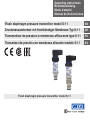
Operating instructions
Betriebsanleitung
Mode d'emploi
Manual de instrucciones
Druckmessumformer mit frontbündiger Membrane Typ S-11
Flush diaphragm pressure transmitter model S-11
Flush diaphragm pressure transmitter model S-11
Transmisor de presión con membrana aflorante modelo
S-11
Transmetteur de pression à membrane affleurante type S-11

2 WIKA operating instructions pressure transmitter, model S-11
EN
DE
FR
ES
14043046.02 08/2019 EN/DE/FR/ES
© 2012 WIKA Alexander Wiegand SE & Co. KG
All rights reserved. / Alle Rechte vorbehalten.
WIKA
®
is a registered trademark in various countries.
WIKA
®
ist eine geschützte Marke in verschiedenen Ländern.
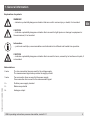
Prior to starting any work, read the operating instructions!
Keep for later use!
Vor Beginn aller Arbeiten Betriebsanleitung lesen!
Zum späteren Gebrauch aufbewahren!
Lire le mode d‘emploi avant de commencer toute opération !
A conserver pour une utilisation ultérieure !
¡Leer el manual de instrucciones antes de comenzar cualquier trabajo!
¡Guardar el manual para una eventual consulta posterior!
Operating instructions model S-11 Page 3 - 24
Betriebsanleitung Typ S-11 Seite 25 - 46
Mode d'emploi type S-11 Page 47 - 68
Manual de instrucciones modelo S-11 Página 69 - 91

3WIKA operating instructions pressure transmitter, model S-11
EN
14043046.02 08/2019 EN/DE/FR/ES
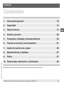
1. General information 4
2. Safety 6
3. Specications 8
4. Design and function 14
5. Transport, packaging and storage 14
6. Commissioning, operation 15
7. Adjustment of zero point and span 20
8. Maintenance and cleaning 21
9. Faults 21
10. Dismounting, return and disposal 22
Contents
Contents
Declarations of conformity can be found online at www.wika.com.

4 WIKA operating instructions pressure transmitter, model S-11
EN
14043046.02 08/2019 EN/DE/FR/ES
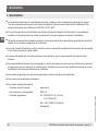
1. General information
■
The pressure transmitter described in the operating instructions has been designed and manufactured using state-
of-the-art technology. All components are subject to stringent quality and environmental criteria during production.
Our management systems are certied to ISO 9001 and ISO 14001.
■
These operating instructions contain important information on handling the instrument. Working safely requires that
all safety instructions and work instructions are observed.
■
Observe the relevant local accident prevention regulations and general safety regulations for the instrument's range
of use.
■
The operating instructions are part of the product and must be kept in the immediate vicinity of the instrument and
readily accessible to skilled personnel at any time.
■
Skilled personnel must have carefully read and understood the operating instructions, prior to beginning any work.
■
The manufacturer's liability is void in the case of any damage caused by using the product contrary to its intended
use, non-compliance with these operating instructions, assignment of insuciently qualied skilled personnel or
unauthorised modications to the instrument.
■
The general terms and conditions contained in the sales documentation shall apply.
■
Subject to technical modications.
■
Further information:
- Internet address: www.wika.de / www.wika.com
- Relevant data sheet: PE 81.02
- Application consultant:
Tel.: +49 9372 132-0
Fax: +49 9372 132-406
E-mail: [email protected]
1. General information

5WIKA operating instructions pressure transmitter, model S-11
EN
14043046.02 08/2019 EN/DE/FR/ES
1. General information
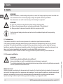
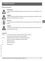
Explanation of symbols
WARNING!
... indicates a potentially dangerous situation that can result in serious injury or death, if not avoided.
CAUTION!
... indicates a potentially dangerous situation that can result in light injuries or damage to equipment or
the environment, if not avoided.
Information
… points out useful tips, recommendations and information for ecient and trouble-free operation.
CAUTION!
... indicates a potentially dangerous situation that can result in burns, caused by hot surfaces or liquids, if
not avoided.
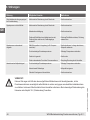
Abbreviations
2-wire The two connection lines are used for the voltage supply.
The measurement signal also provides the supply current.
3-wire Two connection lines are used for the power supply.
One connection line is used for the measurement signal.
U
+
Positive power supply terminal
U
-
Reference potential
S
+
Analogue output

6 WIKA operating instructions pressure transmitter, model S-11
EN
14043046.02 08/2019 EN/DE/FR/ES
2. Safety
2. Safety
WARNING!
Before installation, commissioning and operation, ensure that the appropriate pressure transmitter has
been selected in terms of measuring range, design and specic measuring conditions.
Non-observance can result in serious injury and/or damage to equipment.
WARNING!
■
Open the connections only after the system has been depressurised.
■
Observe the working conditions in accordance with chapter 3 “Specications”.
■
Always operate the pressure transmitter within the overpressure limit.
Further important safety instructions can be found in the individual chapters of these operating
instructions.
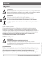
2.1 Intended use
The pressure transmitter is used to convert pressure into an electrical signal indoors and outdoors.
The instrument has been designed and built solely for the intended use described here, and may only be used
accordingly. The technical specications contained in these operating instructions must be observed. Improper
handling or operation of the pressure transmitter outside of its technical specications requires the instrument to be
taken out of service immediately and inspected by an authorised WIKA service engineer.
The manufacturer shall not be liable for claims of any type based on operation contrary to the intended use.
2.2 Personnel qualication
WARNING!
Risk of injury should qualication be insucient!
Improper handling can result in considerable injury and damage to equipment.
The activities described in these operating instructions may only be carried out by skilled personnel who
have the qualications described below.
Skilled personnel
Skilled personnel are understood to be personnel who, based on their technical training, knowledge of measurement
and control technology and on their experience and knowledge of country-specic regulations, current standards and
directives, are capable of carrying out the work described and independently recognising potential hazards.
Special operating conditions require further appropriate knowledge, e.g. of aggressive media.

7WIKA operating instructions pressure transmitter, model S-11
EN
14043046.02 08/2019 EN/DE/FR/ES
2. Safety
2.3 Special hazards
WARNING!
For hazardous media such as oxygen, acetylene, ammable or toxic gases or liquids, and refrigeration
plants, compressors, etc., in addition to all standard regulations, the appropriate existing codes or
regulations must also be followed.
WARNING!
Residual media in the dismounted pressure transmitter can result in a risk to persons, the environment
and equipment.
Take sucient precautionary measures.
Do not use this instrument in safety or emergency stop devices. Incorrect use of the instrument can result
in injury.
Should a failure occur, aggressive media with extremely high temperature and under high pressure or
vacuum may be present at the instrument.
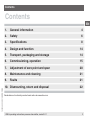
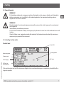
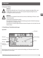
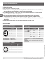
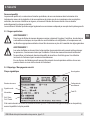
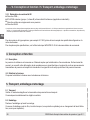
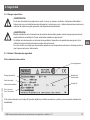
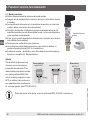
2.4 Labelling / safety marks
Product label
Output signal
Pin assignment
Power supply
S# Serial no.
P# Product no.
Measuring range
2D code
Approvals
If the serial number and the 2D code become illegible due to mechanical damage or overpainting, traceability will no
longer be possible.

8 WIKA operating instructions pressure transmitter, model S-11
EN
14043046.02 08/2019 EN/DE/FR/ES
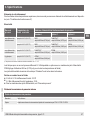
3. Specifications
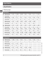
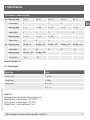
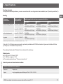
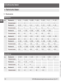
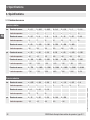
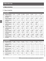
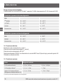
3.1 Measuring ranges
Gauge pressure
bar Measuring range 0 ... 0.1 0 ... 0.16 0 ... 0.25 0 ... 0.4 0 ... 0.6 0 ... 1 0 ... 1.6
Overload safety 1 1.5 2 2 4 5 10
Measuring range 0 ... 2.5 0 ... 4 0 ... 6 0 ... 10 0 ... 16 0 ... 25 0 ... 40
Overload safety 10 17 35 35 80 50 80
Measuring range 0 ... 60 0 ... 100 0 ... 160 0 ... 250 0 ... 400 0 ... 600
Overload safety 120 200 320 500 800 1,200
psi Measuring range 0 ... 15 0 ... 20 0 ... 30 0 ... 50 0 ... 60 0 ... 100 0 ... 150
Overload safety 145 145 145 240 240 500 500
Measuring range 0 ... 160 0 ... 200 0 ... 250 0 ... 300 0 ... 400 0 ... 500 0 ... 600
Overload safety 1,160 1,160 1,160 1,160 1,160 1,160 1,160
Measuring range 0 ... 750 0 ... 1,000 0 ... 1,500 0 ... 2,000 0 ... 3,000 0 ... 5,000 0 ... 6,000
Overload safety 1,740 1,740 2,900 4,600 7,200 11,600 11,600
Absolute pressure
bar Measuring range 0 ... 0.25 0 ... 0.4 0 ... 0.6 0 ... 1 0 ... 1.6 0 ... 2.5 0 ... 4
Overload safety 2 2 4 5 10 10 17
Measuring range 0 ... 6 0 ... 10 0 ... 16
Overload safety 35 35 80
psi Measuring range 0 ... 15 0 ... 25 0 ... 50 0 ... 100 0 ... 250
Overload safety 72.5 145 240 500 1,160
3. Specications

9WIKA operating instructions pressure transmitter, model S-11
EN
14043046.02 08/2019 EN/DE/FR/ES
3. Specications
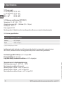
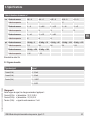
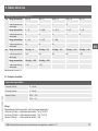
Vacuum and +/- measuring range
bar Measuring range -0.6 ... 0 -0.4 ... 0 -0.25 ... 0 -0.16 ... 0 -0.1 ... 0
Overload safety 4 2 2 1.5 1
Measuring range -1 ... 0 -1 ... +0.6 -1 ... +1.5 -1 ... +3 -1 ... +5
Overload safety 5 10 10 17 35
Measuring range -1 ... +9 -1 ... +15 -1 ... +24
Overload safety 35 80 50
psi Measuring range -30 inHg ... 0 -30 inHg ... +30 -30 inHg ... +60 -30 inHg ... +100 -30 inHg ... +160
Overload safety 72.5 240 240 500 1,160
Measuring range -30 inHg ... +200 -30 inHg ... +300
Overload safety 1,160 1,160
Vacuum tightness: Yes
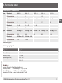
3.2 Output signals
Signal type Signal
Current (2-wire) 4 ... 20 mA
Current (3-wire) 0 ... 20 mA
Voltage (3-wire) DC 0 ... 10 V
DC 0 ... 5 V
Load in Ω
Depending on the signal type the following loads apply:
Current (2-wire): ≤ (power supply - 10 V) / 0.02 A
Current (3-wire): ≤ (power supply - 3 V) / 0.02 A
Voltage (3-wire): > max. output signal / 1 mA

10 WIKA operating instructions pressure transmitter, model S-11
EN
14043046.02 08/2019 EN/DE/FR/ES
3. Specications
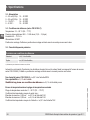
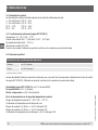
3.3 Power supply
4 ... 20 mA (2-wire): DC 10 ...30 V
0 ... 20 mA (3-wire): DC 10 ...30 V
DC 0 ... 10 V: DC 14 ... 30 V
DC 0 ... 5 V: DC 10 ...30 V
3.4 Reference conditions (per IEC 61298-1)
Temperature: 15 ... 25 °C (59 ... 77 °F)
Atmospheric pressure: 860 ... 1,060 mbar (12.5 ... 15.4 psi)
Humidity: 45 ... 75 % r. h.
Power supply: DC 24 V
Mounting position: Calibrated in vertical mounting position with process connection facing downwards.
3.5 Accuracy specications
Accuracy at reference conditions
Standard ≤ ±0.5 % of span
Option ≤ ±0.25 % of span
1)
1) Only for measuring ranges ≥ 0.25 bar
Including non-linearity, hysteresis, zero oset and end value deviation (corresponds to measured error per
IEC 61298-2). Calibrated in vertical mounting position with process connection facing downwards.
Non-linearity (per IEC 61298-2): ≤ ±0.2 % of span BFSL
Non-repeatability: ≤ 0.1 % of span
Long-term stabilty at reference conditions: ≤ ±0.2 % of span/year
Temperature error in rated temperature range
Rated temperature range: 0 ... 80 °C (32 ... 176 °F)
Mean temperature coecient of zero point:
Measuring range > 0.25 bar: ≤ ±0.2 % of span/10 K
Measuring range ≤ 0.25 bar: < ±0.4 % of span/10 K
Mean temperature coecient of span: ≤ ±0.2 % of span/10 K

11WIKA operating instructions pressure transmitter, model S-11
EN
14043046.02 08/2019 EN/DE/FR/ES
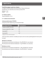
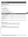
Adjustability of zero point and span
Adjustment is made using potentiometers inside the instrument.
Not possible for IP68 cable outlet.
Zero point: ± 5 %
Span: ± 5 %
3.6 Time response
Settling time: ≤ 2 ms
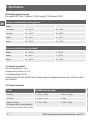
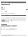
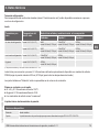
3.7 Operating conditions
Ingress protection (per IEC 60529)
The ingress protection depends on the type of electrical connection.
Electrical connection Ingress protection
Angular connector DIN 175301-803 A IP65
Circular connector M12 x 1 (4-pin) IP67
Cable outlet IP67 IP67
Cable outlet IP68 IP68
1)
1) Adjustability of zero point and span not possible.
The stated ingress protection only applies when plugged in using mating connectors that have the appropriate ingress
protection.
Vibration resistance
Process connections without cooling element: 20 g (IEC 60068-2-6, under resonance)
Process connections with cooling element: 10 g (IEC 60068-2-6, under resonance)
Shock resistance
Process connections without cooling element: 1,000 g (IEC 60068-2-27, mechanical)
Process connections with cooling element:
400 g (IEC 60068-2-27, mechanical)
3. Specications

12 WIKA operating instructions pressure transmitter, model S-11
EN
14043046.02 08/2019 EN/DE/FR/ES
3. Specications
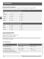
Permissible temperature ranges
Also meets EN 50178, tab. 7, operation (C) 4K4H, storage (D) 1K4, transport (E) 2K3.
Process connections without cooling element
Medium
■
Standard -30 ... +100 °C -22 ... +212 °F
■
Option -30 ... +125 °C -22 ... +257 °F
Ambient -20 ... +80 °C -4 ... +176 °F
Storage -40 ... +100 °C -40 ... +212 °F
Process connections with cooling element
Medium -20 ... +150 °C -4 ... +302 °F
Ambient -20 ... +80 °C -4 ... +176 °F
Storage -40 ... +100 °C -40 ... +212 °F
3.8 Electrical connections
Short-circuit resistance: S+ vs. U-
Reverse polarity protection: U+ vs. U-
Overvoltage protection: DC 36 V
Insulation voltage: DC 500 V with NEC class 02 voltage supply (low voltage and low current max. 100 VA even under
fault conditions)
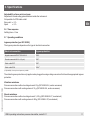
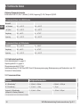
3.9 Process connections
Thread Available measuring ranges
G ½ B ush
1)
0 ... 2.5 to 0 ... 600 bar 0... 50 to 0 ... 6,000 psi
G 1 B ush
1)
0 ... 0.1 to 0 ... 1.6 bar 0 ... 15 psi
Hygienic G 1 B ush
(in accordance with 3-A Sanitary Standards)
0 ... 0.1 to 0 ... 25 bar 0 ... 15 to 0 ... 300 psi
1) Process connection also available with cooling element.

13WIKA operating instructions pressure transmitter, model S-11
EN
14043046.02 08/2019 EN/DE/FR/ES
3. Specications
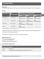
Cooling elements
For higher medium temperatures, process connections with a cooling element are available (see “Operating conditions”).
Sealing
Process
connection
Max. medium
temperature
Sealing material and max. pressure limitation
Standard Option 1 Option 2
without cooling element up to 100 °C (212 °F) NBR
up to 600 bar (8,700 psi)
FKM/FPM
1)
up to 600 bar (8,700 psi)
EPDM
up to 200 bar (2,900 psi)
up to 125 °C (257 °F) NBR
up to 600 bar (8,700 psi)
FKM/FPM
1)
up to 400 bar (5,800 psi)
EPDM
up to 200 bar (2,900 psi)
with cooling element up to 150 °C (302 °F) FKM/FPM
1)
up to 300 bar (4,350 psi)
EPDM
up to 200 bar (2,900 psi)
-
Hygienic up to 150 °C (302 °F) EPDM
up to 200 bar (2,900 psi)
- -
1) Minimum permissible medium and ambient temperature -20 °C / -4 °F
O-ring for G ½ B ush process connection optionally available with FFKM seal material (pressure limitation 600 bar
(8,700 psi) for all medium temperatures)
The sealings listed under “Standard” are included in the delivery.
Wetted parts
■
G ½ B and G 1 B ush: 316TI
■
G 1 B ush, hygienic: 316L
■
For sealing materials see “Process connections”
Internal pressure transmission medium
Pressure transmission medium
Standard Synthetic oil
Option Food-compatible system ll uid per FDA 21 CFR 178.3750

14 WIKA operating instructions pressure transmitter, model S-11
EN
14043046.02 08/2019 EN/DE/FR/ES
3. ... / 4. Design and function / 5. Transport, packaging and storage
3.10 EU declaration of conformity
■
EMC directive
1)
■
EN 61326 emission (group 1, class B) and interference immunity (industrial application)
■
Pressure equipment directive
■
RoHS directive
1) The existence of strong electromagnetic elds in a frequency range of < 2.7 GHz can result in increased measuring errors up to 1 %. Do not install the instruments in
the vicinity of strong electromagnetic sources of interference (e.g. transmitting devices, radio equipment), or use sheath current lters where applicable.
For special model numbers, e.g. S-11000, please note the specications stated on the delivery note.
For further specications see WIKA data sheet PE 81.02 and the order documentation.
4. Design and function
4.1 Description
The prevailing pressure is measured at the sensor element through the deformation of a diaphragm. By supplying
power, this deformation of the diaphragm is converted into an electrical signal. The output signal from the pressure
transmitter is amplied and standardised. The output signal is proportional to the measured pressure.
4.2 Scope of delivery
Cross-check the scope of delivery with the delivery note.
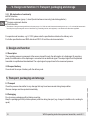
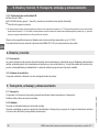
5. Transport, packaging and storage
5.1 Transport
Check the pressure transmitter for any damage that may have been caused during transportation.
Obvious damage must be reported immediately.
5.2 Packaging
Do not remove packaging until just before mounting.
Keep the packaging as it will provide optimum protection during transport (e.g. change in installation site, sending for
repair).

15WIKA operating instructions pressure transmitter, model S-11
EN
14043046.02 08/2019 EN/DE/FR/ES
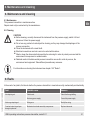
5.3 Storage
Permissible conditions at the place of storage:
■
Storage temperature: see chapter 3 “Specications”
■
Humidity: 45 ... 75 % relative humidity
Avoid exposure to the following factors:
■
Mechanical vibration, mechanical shock (putting it down hard)
■
Soot, vapour, dust and corrosive gases
■
Potentially explosive environments, ammable atmospheres
Store the pressure transmitter in its original packaging in a location that fulls the conditions listed above. If the original
packaging is not available, pack and store the instrument as described below:
1. Place the protection cap on the process connection
2. Place the instrument, along with shock-absorbent material, in the packaging.
WARNING!
Before storing the instrument (following operation), remove any residual media. This is of particular
importance if the medium is hazardous to health, e.g. caustic, toxic, carcinogenic, radioactive, etc..
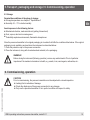
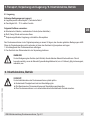
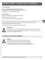
6. Commissioning, operation
CAUTION!
Prior to commissioning, the pressure transmitter must be subjected to a visual inspection.
■
Leaking uid is indicative of damage.
■
Check the diaphragm of the process connection for any damage.
■
Only use the pressure transmitter if it is in perfect condition with respect to safety.
5. Transport, packaging and storage / 6. Commissioning, operation

16 WIKA operating instructions pressure transmitter, model S-11
EN
14043046.02 08/2019 EN/DE/FR/ES
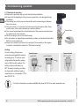
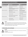
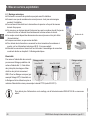
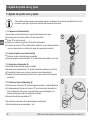
6.1 Mechanical mounting
■
Remove the protection cap not until shortly before installation.
■
Ensure that the diaphragm of the process connection is not damaged during
installation.
■
The sealing faces at the pressure transmitter and the measuring point always
have to be clean.
■
Only ever screw in, or unscrew, the instrument using the spanner ats. Never
use the case or the cooling element as a working surface.
■
The correct torque depends on the dimensions of the process connection and
the gasket used (form/material).
■
When screwing in, do not cross the threads.
■
For information on tapped holes and welding sockets, see Technical information
IN 00.14 at www.wika.com.
■
Attach the connector and screw it in hand-tight. The assembly of the angular
connector is described in chapter 6.2 “Electrical mounting”.
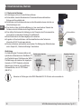
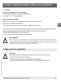
Sealing
Correct sealing of the process
connections with parallel threads at
the sealing face
must be made
using suitable at gaskets, sealing
rings or WIKA prole sealings. The
sealing of tapered threads (e.g.
NPT threads) is made by providing
the thread with additional sealing
material such as, for example, PTFE
tape (EN 837-2).
For further information on seals see WIKA data sheet AC 09.08 or under www.wika.com.
Spanner ats
Parallel thread Tapered thread
per EN 837 per DIN 3852-E
NPT, R and PT
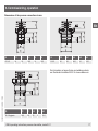
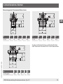
6. Commissioning, operation

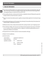
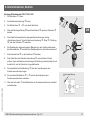
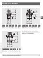
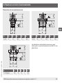
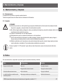
G D1 L1 L2 L3 L4
G ½ B 18 23 20.5 10 15.5
G D1 L1 L2 L3 L4
G 1 B 30 23 20.5 10 15.5
G D1 L1 L2 L3 L4
G 1 B hygienic 29.5 28 25 9 15.5
17WIKA operating instructions pressure transmitter, model S-11
EN
14043046.02 08/2019 EN/DE/FR/ES
For information on tapped holes and welding sockets,
see Technical information IN 00.14 at www.wika.com.
6. Commissioning, operation
Dimensions of the process connections in mm

18 WIKA operating instructions pressure transmitter, model S-11
EN
14043046.02 08/2019 EN/DE/FR/ES
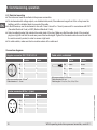
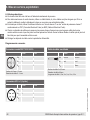
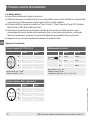
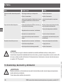
Circular connector M12 x 1 (4-pin)
2-wire 3-wire
U
+
1 1
U
-
3 3
S
+
- 4
Cable outlet, unshielded
2-wire 3-wire
U
+
brown brown
U
-
green green
S
+
- white
Wire cross-section 3 x 0.5 mm
2
Cable diameter 6.8 mm
Cable lengths 1.5 m, 3 m, 5 m, 10 m, 15 m
Angular connector DIN 175301-803 A
2-wire 3-wire
U
+
1 1
U
-
2 2
S
+
- 3
Wire cross-section max. 1.5 mm
2
Cable diameter 6 ... 8 mm
6. Commissioning, operation
6.2 Electrical mounting
■
The instrument must be earthed via the process connection.
■
For instruments with voltage output, use shielded cable, and, if the cables are longer than 30 m or they leave the
building, earth the shield at least at one end of the cable.
■
In North America, use the instrument in line with "class 2 circuits" or "class 2 power units" in accordance with CEC
(Canadian Electrical Code) or NEC (National Electrical Code).
■
Select a cable diameter that matches the cable gland of the plug. Make sure that the cable gland of the mounted
plug has a tight t and that the seals are present and undamaged. Tighten the threaded connection and check that
the seal is correctly seated, in order to ensure a tight seal.
■
For cable outlets, make sure that no moisture enters at the cable end.
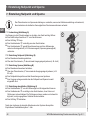
Connection diagrams

19WIKA operating instructions pressure transmitter, model S-11
EN
14043046.02 08/2019 EN/DE/FR/ES
6. Commissioning, operation
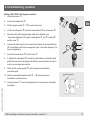
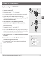
Fitting a DIN 175301-803 angular connector
1. Loosen the screw
.
2. Loosen the cable gland
.
3. Pull the angled socket
+ from the instrument.
4. Via the mounting hole
, lever the terminal block out of the case .
5. Pass the cable with the appropriate cable outer diameter (see
"Connection diagrams") through the cable gland
, ring , sealing
and the case
.
6. Connect the cable ends to the connection terminals on the terminal block
in accordance with the pin assignment (see "Connection diagrams" for
the pin assignment).
7. Press the terminal block
into the case .
8. 8. Tighten the cable gland
around the cable. Make sure that the cable
gland and seal are not damaged and that they are assembled correctly in
order to ensure ingress protection.
9. Place the at, square gasket
over the pressure transmitter's
connection pins.
10. Slide the assembled angled socket
+ onto the pressure
transmitter's connection pins.
11. Using the screw
, screw the angled socket to the pressure transmitter,
hand-tight.
Mounting hole

20 WIKA operating instructions pressure transmitter, model S-11
EN
14043046.02 08/2019 EN/DE/FR/ES
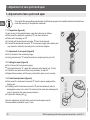
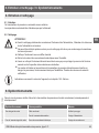
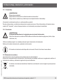
7. Adjustment of zero point and span
7. Adjustment of zero point and span
Only adjust the span-setting potentiometer if calibration equipment is available which has at least three
times the accuracy of the pressure transmitter.
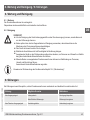
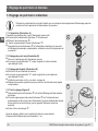
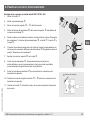
7.1 Preparation (gure A)
To gain access to the potentiometers, open the instrument as follows:
■
Disconnect the electrical connection from the instrument.
■
Remove the clamping nut .
■
Carefully pull the instrument connector from the instrument.
■
Connect the instrument connector to the power supply and a display unit
(e.g. ammeter, voltmeter) according to the connection diagram.
7.2 Adjustment of zero point (gure B)
■
Go to the start of the measuring range.
■
Using potentiometer "Z", adjust the minimum output signal (e.g. 4 mA)
7.3 Setting the span (gure B)
■
Go to the end of the measuring range.
■
Using potentiometer "S", adjust the maximum output signal (e.g. 20 mA)
■
Check the zero point and if there is any deviation, re-adjust it.
■
Repeat the procedure until the zero point and the span are set correctly.
7.4 Finish the adjustment (gure A)
■
Disconnect the instrument connector from the power supply and the
display unit.
■
Carefully push the instrument connector onto the instrument, without
damaging the wires or the seals. The seals must be clean and undamaged in
order to guarantee the given ingress protection.
■
Tighten the clamping nut
.
After the adjustment, check that the system is functioning correctly.
Recommended recalibration cycle: 1 year
A
B
Seite laden ...
Seite laden ...
Seite laden ...
Seite laden ...
Seite laden ...
Seite laden ...
Seite laden ...
Seite laden ...
Seite laden ...
Seite laden ...
Seite laden ...
Seite laden ...
Seite laden ...
Seite laden ...
Seite laden ...
Seite laden ...
Seite laden ...
Seite laden ...
Seite laden ...
Seite laden ...
Seite laden ...
Seite laden ...
Seite laden ...
Seite laden ...
Seite laden ...
Seite laden ...
Seite laden ...
Seite laden ...
Seite laden ...
Seite laden ...
Seite laden ...
Seite laden ...
Seite laden ...
Seite laden ...
Seite laden ...
Seite laden ...
Seite laden ...
Seite laden ...
Seite laden ...
Seite laden ...
Seite laden ...
Seite laden ...
Seite laden ...
Seite laden ...
Seite laden ...
Seite laden ...
Seite laden ...
Seite laden ...
Seite laden ...
Seite laden ...
Seite laden ...
Seite laden ...
Seite laden ...
Seite laden ...
Seite laden ...
Seite laden ...
Seite laden ...
Seite laden ...
Seite laden ...
Seite laden ...
Seite laden ...
Seite laden ...
Seite laden ...
Seite laden ...
Seite laden ...
Seite laden ...
Seite laden ...
Seite laden ...
Seite laden ...
Seite laden ...
Seite laden ...
Seite laden ...
-
 1
1
-
 2
2
-
 3
3
-
 4
4
-
 5
5
-
 6
6
-
 7
7
-
 8
8
-
 9
9
-
 10
10
-
 11
11
-
 12
12
-
 13
13
-
 14
14
-
 15
15
-
 16
16
-
 17
17
-
 18
18
-
 19
19
-
 20
20
-
 21
21
-
 22
22
-
 23
23
-
 24
24
-
 25
25
-
 26
26
-
 27
27
-
 28
28
-
 29
29
-
 30
30
-
 31
31
-
 32
32
-
 33
33
-
 34
34
-
 35
35
-
 36
36
-
 37
37
-
 38
38
-
 39
39
-
 40
40
-
 41
41
-
 42
42
-
 43
43
-
 44
44
-
 45
45
-
 46
46
-
 47
47
-
 48
48
-
 49
49
-
 50
50
-
 51
51
-
 52
52
-
 53
53
-
 54
54
-
 55
55
-
 56
56
-
 57
57
-
 58
58
-
 59
59
-
 60
60
-
 61
61
-
 62
62
-
 63
63
-
 64
64
-
 65
65
-
 66
66
-
 67
67
-
 68
68
-
 69
69
-
 70
70
-
 71
71
-
 72
72
-
 73
73
-
 74
74
-
 75
75
-
 76
76
-
 77
77
-
 78
78
-
 79
79
-
 80
80
-
 81
81
-
 82
82
-
 83
83
-
 84
84
-
 85
85
-
 86
86
-
 87
87
-
 88
88
-
 89
89
-
 90
90
-
 91
91
-
 92
92


in anderen Sprachen
- français: WIKA S-11 Mode d'emploi
- español: WIKA S-11 Instrucciones de operación
Verwandte Papiere
-
WIKA OT-1 Bedienungsanleitung
-
-
-
-
-
-
-
-
-
Sonstige Unterlagen
-
Baumer Motor supply cable 10 m, 8-pin mating connector (Z 165.M03) Datenblatt
-
SICK PET Pressure transmitter Bedienungsanleitung
-
 Tecsis P3322 Benutzerhandbuch
-
Sames One flat seal ram plates Ø 280-285 Benutzerhandbuch
-
Ashcroft KX1 Bedienungsanleitung
-
 Norma NORMACONNECT PLAST GRIP Fitting Instructions Manual

