Operating instructions
Betriebsanleitung
Mode d'emploi
Manual de instrucciones
EN
DE
FR
ES
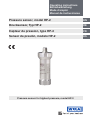
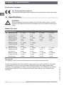
Drucksensor, Typ HP-2
Pressure sensor for highest pressure, model HP-2
Pressure sensor, model HP-2
Capteur de pression, type HP-2
Sensor de presión, modelo HP-2

2
11379180.04 05/2018 EN/DE/FR/ES
WIKA operating instructions pressure sensor, model HP-2
EN
DE
FR
ES
© 2012 WIKA Alexander Wiegand SE & Co. KG
All rights reserved. / Alle Rechte vorbehalten.
WIKA
®
is a registered trademark in various countries.
WIKA
®
ist eine geschützte Marke in verschiedenen Ländern.
Prior to starting any work, read the operating instructions!
Keep for later use!
Vor Beginn aller Arbeiten Betriebsanleitung lesen!
Zum späteren Gebrauch aufbewahren!
Lire le mode d'emploi avant de commencer toute opération !
A conserver pour une utilisation ultérieure !
¡Leer el manual de instrucciones antes de comenzar cualquier trabajo!
¡Guardar el manual para una eventual consulta!
Operating instructions model HP-2 Page
3 - 22
Betriebsanleitung Typ HP-2 Seite
23 - 42
Mode d'emploi type HP-2 Page
43 - 62
Manual de instrucciones modelo HP-2 Página
63 - 82

3
WIKA operating instructions pressure sensor, model HP-2
11379180.04 05/2018 EN/DE/FR/ES
EN
Contents
Contents
1. General information 4
2. Safety 5
3. Specications 8
4. Design and function 10
5. Transport, packaging and storage 10
6. Commissioning, operation 11
7. Adjustment of zero point and span 14
8. Spare part kit 15
9. Maintenance and cleaning 18
10. Faults 19
11. Dismounting, return and disposal 20
12. Accessories 21
Declarations of conformity can be found online at www.wika.com.

4
WIKA operating instructions pressure sensor, model HP-2
11379180.04 05/2018 EN/DE/FR/ES
EN
1. General information
1. General information
■
The pressure sensor described in the operating instructions has been designed and
manufactured using state-of-the-art technology. All components are subject to strin-
gent quality and environmental criteria during production. Our management systems
are certied to ISO 9001 and ISO 14001.
■
These operating instructions contain important information on handling the instru-
ment. Working safely requires that all safety instructions and work instructions are
observed.
■
Observe the relevant local accident prevention regulations and general safety regula-
tions for the instrument's range of use.
■
The operating instructions are part of the product and must be kept in the immediate
vicinity of the instrument and readily accessible to skilled personnel at any time.
■
Skilled personnel must have carefully read and understood the operating instructions
prior to beginning any work.
■
The manufacturer's liability is void in the case of any damage caused by using the
product contrary to its intended use, non-compliance with these operating instruc-
tions, assignment of insuciently qualied skilled personnel or unauthorised modi-
cations to the instrument.
■
The general terms and conditions contained in the sales documentation shall apply.
■
Subject to technical modications.
■
Further information:
- Internet address: www.wika.de / www.wika.com
- Relevant data sheet: PE 81.53
- Application consultant:
Tel.: +49 9372 132-8976
Fax: +49 9372 132-8008976

5
WIKA operating instructions pressure sensor, model HP-2
11379180.04 05/2018 EN/DE/FR/ES
EN
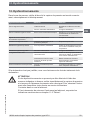
1. General information / 2. Safety
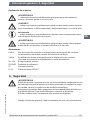
Explanation of symbols
WARNING!
... indicates a potentially dangerous situation that can result in serious injury
or death, if not avoided.
CAUTION!
... indicates a potentially dangerous situation that can result in light injuries
or damage to equipment or the environment, if not avoided.
Information
... points out useful tips, recommendations and information for ecient and
trouble-free operation.
WARNING!
... indicates a potentially dangerous situation that can result in burns, caused
by hot surfaces or liquids, if not avoided.
Abbreviations
2-wire The two connection lines are used for the voltage supply.
The measurement signal also provides the supply current.
3-wire Two connection lines are used for the voltage supply.
One connection line is used for the measurement signal.
U
B
, +5V Positive power supply
0V, GND Reference potential
S+ Positive output terminal
D+ ,D- Data link USB 2.0
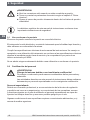
2. Safety
WARNING!
Before installation, commissioning and operation, ensure that the appropri-
ate pressure sensor has been selected in terms of measuring range, design
and specic measuring conditions.
The operator must ensure the compatibility of the uid with the material
used. Where the medium is hydrogen, contact the manufacturer.
The uid must not be contaminated with abrasive substances.
Non-observance can result in serious injury and/or damage to the equipment.

6
WIKA operating instructions pressure sensor, model HP-2
11379180.04 05/2018 EN/DE/FR/ES
EN
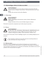
2. Safety
WARNING!
■
Open the connections only after the system has been depressurised.
■
Observe the working conditions in accordance with chapter 3 “Specica-
tions”.
■
Always operate the pressure sensor within the overpressure limit.
Further important safety instructions can be found in the individual chapters
of these operating instructions.
2.1 Intended use
The pressure sensor is used to convert pressure into an electrical signal.
The instrument has been designed and built solely for the intended use described here,
and may only be used accordingly.
The technical specications contained in these operating instructions must be
observed. Improper handling or operation of the instrument outside of its techni-
cal specications requires the instrument to be taken out of service immediately and
inspected by an authorised WIKA service engineer.
The manufacturer shall not be liable for claims of any type based on operation contrary
to the intended use.
2.2 Personnelqualication
WARNING!
Riskofinjuryshouldqualicationbeinsucient!
Improper handling can result in considerable injury and damage to equipment.
The activities described in these operating instructions may only be carried
out by skilled personnel who have the qualications described below.
Skilled personnel
Skilled personnel are understood to be personnel who, based on their technical training,
knowledge of measurement and control technology and on their experience and knowl-
edge of country-specic regulations, current standards and directives, are capable of
carrying out the work described and independently recognising potential hazards.
Special operating conditions require further appropriate knowledge, e.g. of aggressive
media.

7
WIKA operating instructions pressure sensor, model HP-2
11379180.04 05/2018 EN/DE/FR/ES
EN
2. Safety
2.3 Special hazards
WARNING!
For hazardous media such as oxygen, acetylene, ammable or toxic gases
or liquids, and refrigeration plants, compressors, etc., in addition to all stand-
ard regulations, the appropriate existing codes or regulations must also be
followed.
WARNING!
No plant conditions are permitted that could lead to the formation of atomic
hydrogen in the connection channel of the pressure sensor.
WARNING!
Residual media in the dismounted pressure sensor can result in a risk to
persons, the environment and equipment.
Take sucient precautionary measures.
Do not use this instrument in safety or emergency stop devices. Incorrect use
of the instrument can result in injury.
Should a failure occur, aggressive media with extremely high temperature and
under high pressure or vacuum may be present at the instrument.
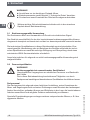
2.4 Labelling, safety marking
Product label
If the serial number becomes illegible due to mechanical damage or overpainting, trace-
ability will no longer be possible.
P# Product no.
S# Serial no.
Measuring range
Power supply
Output signal
Pin assignment
Accuracy

8
WIKA operating instructions pressure sensor, model HP-2
11379180.04 05/2018 EN/DE/FR/ES
EN
2.Safety/3.Specications
Explanation of symbols
CE, Communauté Européenne
Instruments bearing this mark comply with the relevant European directives.
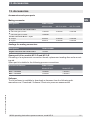
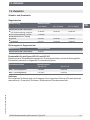
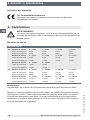
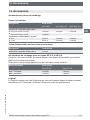
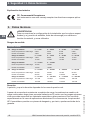
3. Specications
WARNING!
When designing the system, please note that the values given (e.g. burst
pressure, overpressure limit) are dependent upon the material and thread
used.
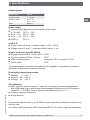
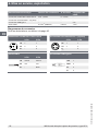
Measuring ranges
Relative pressure
bar Measuring range 0 ... 1,600 0 ... 2,500 0 ... 4,000 0 ... 5,000
Overpressure limit 2,300 3,500 5,000 6,000
Burst pressure 4,000 6,000 8,000 10,000
Measuring range 0 ... 6,000 0 ... 7,000 0 ... 8,000 0 ... 10,000
Overpressure limit 7,000 8,000 10,000 11,000
Burst pressure 11,000 11,000 12,000 12,000
Measuring range 0 ... 12,000 0 ... 15,000
Overpressure limit 12,500 15,500
Burst pressure 14,000 16,000
psi Measuring range 0 ... 23,000 0 ... 36,000 0 ... 58,000 0 ... 72,000
Overpressure limit 33,300 50,500 72,500 87,000
Burst pressure 58,000 87,000 116,000 145,000
Measuring range 0 ... 87,000 0 ... 100,000 0 ... 115,000 0 ... 145,000
Overpressure limit 101,500 116,000 145,000 159,000
Burst pressure 159,500 159,500 174,000 174,000
Service life
On request, since the service life depends on the actual pressure prole.
Despite its excellent load cycle stability a permanent load cycle stability is only given
conditionally. This is due to the extreme loadings faced by the highly pressurised
materials. This applies particularly to dynamic applications. Accordingly, the pressure-
loaded parts of the HP-2 are considered as wear parts that are not covered by the
warranty.

9
WIKA operating instructions pressure sensor, model HP-2
11379180.04 05/2018 EN/DE/FR/ES
EN
3.Specications
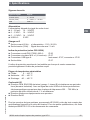
Output signals
Signal type Signal
Current (2-wire) 4 ... 20 mA
Voltage (3-wire) DC 0 ... 5 V
DC 0 ... 10 V
USB USB 2.0
Power supply
The power supply depends on the selected output signal
■
4 ... 20 mA: DC 10 ... 30 V
■
DC 0 ... 5 V: DC 10 ... 30 V
■
DC 0 ... 10 V: DC 14 ... 30 V
■
USB 2.0: DC 5 V
LoadinΩ
■
Current output (2-wire): ≤ (power supply - 10 V) / 0.02 A
■
Voltage output (3-wire): > maximum output signal / 1 mA
Ingress protection (per IEC 60529)
■
Angular connector DIN 175301-803 A: IP 65
■
Circular connector M12 x 1 (4-pin): IP 67
■
USB connector type A: Instrument: IP 67, connector: IP 20
■
Cable outlet: IP 67
The stated ingress protection only applies when plugged in using mating connectors
that have the appropriate ingress protection.
Permissible temperature ranges
■
Medium: 0 ... +80 °C
■
Ambient: -20 ... +80 °C
■
Storage: -40 ... +85 °C
CE conformity
■
EMC directive, emission (group 1, class B) and immunity (industrial application)
With USB signal output and strong electromagnetic disturbances in the frequency
range 650 … 750 MHz, the accuracy can be inuenced by up to 1 %.
■
Pressure equipment directive
■
RoHS directive
For special model numbers, e.g. HP-20000, please note the specications stated on the
delivery note.
For further specications see WIKA data sheet PE 81.53 and the order documentation.

10
WIKA operating instructions pressure sensor, model HP-2
11379180.04 05/2018 EN/DE/FR/ES
EN
4. Design and function / 5. Transport, packaging and ...
4. Design and function
4.1 Short description
The prevailing pressure is measured at the sensor element through the deformation of a
diaphragm. By supplying power, this deformation of the diaphragm is converted into an
electrical signal. The output signal from the pressure sensor is amplied and standard-
ised.
4.2 Scope of delivery
Cross-check scope of delivery with delivery note.
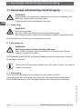
5. Transport, packaging and storage
5.1 Transport
Check the pressure sensor for any damage that may have been caused during transpor-
tation.
Obvious damage must be reported immediately.
5.2 Packaging
Do not remove packaging until just before mounting.
Keep the packaging as it will provide optimum protection during transport (e.g. change
in installation site, sending for repair).
5.3 Storage
Permissible conditions at the place of storage:
see chapter 3 “Specications”
Store the pressure sensor in its original packaging in a location that fulls the conditions
listed above.
WARNING!
Before storing the instrument (following operation), remove any residual
media. This is of particular importance if the medium is hazardous to health,
e.g. caustic, toxic, carcinogenic, radioactive, etc.

11
WIKA operating instructions pressure sensor, model HP-2
11379180.04 05/2018 EN/DE/FR/ES
EN
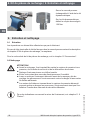
6. Commissioning, operation
6. Commissioning, operation
CAUTION!
Prior to commissioning, the pressure sensor must be subjected to a visual
inspection.
Only use the pressure sensor if it is in perfect condition with respect to
safety.
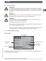
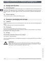
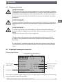
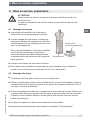
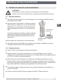
6.1 Mechanical mounting
■
The sealing faces at the instrument have to be
undamaged and clean.
■
When screwing the instrument in, the force
required to do this must not be applied through
the case, but only through the spanner ats
provided for this purpose and using a suitable
tool.
For the installation point, the valid values for
tightening torque and maximum pressure
should be taken from the high-pressure pipe
supplier's documentation.
■
When screwing in, do not cross the threads.
■
For information on tapped holes and welding sockets, see Technical information
IN 00.14 at www.wika.com.
6.2 Electrical mounting
■
The instrument must be grounded via the process connection.
■
Use the pressure sensor with shielded cable, and ground the shield on at least one
end of the lead, if the lines are longer than 30 m (3- or 4-wire) or leave the building.
■
Select a cable diameter that matches the cable gland of the plug. Make sure that
the cable gland of the mounted plug has a tight t and that the seals are present and
undamaged. Tighten the threaded connection and check that the seal is correctly
seated, in order to ensure the ingress protection.
■
For cable outlets, make sure that no moisture enters at the cable end.
■
Observe the specications in accordance with chapter 3 “Specications”.
Spanner ats
Open-ended spanner
(spanner width 27)

12
WIKA operating instructions pressure sensor, model HP-2
11379180.04 05/2018 EN/DE/FR/ES
EN
6. Commissioning, operation
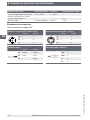
Circular connector M12 x 1 (4-pin)
2-wire 3-wire
U
B
1 1
0V 3 3
S
+
- 4
Cable outlet
2-wire 3-wire
U
B
brown brown
0V green green
S+ - white
Angular connector DIN 175301-803 A
2-wire 3-wire
U
B
1 1
0V 2 2
S+ - 3
USB connector type A
+5V 1
GND 4
D+ 3
D- 2
Electrical connection Wire cross-section Cable∅ Cable
lengths
Angular connector DIN 175301-803 A max. 1.5 mm
2
6 ... 8 mm -
Circular connector M12 x 1 (4-pin) - - -
USB connector type A - - 2 m
Cable outlet 0.5 mm
2
(AWG 20) 6.8 mm 1.5 m
Connection diagrams
For abbreviations see page 5

13
WIKA operating instructions pressure sensor, model HP-2
11379180.04 05/2018 EN/DE/FR/ES
EN
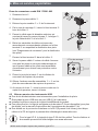
6. Commissioning, operation
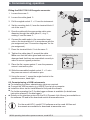
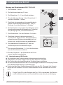
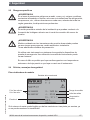
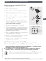
Fitting the DIN 175301-803 angular connector
1.
Loosen the screw .
2.
Loosen the cable gland .
3.
Pull the angled socket + from the instrument.
4.
Via the mounting hole , lever the terminal block
out of the case .
5. Pass the cable with the appropriate cable outer
diameter through the cable gland , ring ,
sealing and the case .
6. Connect the cable ends to the connection termi-
nals on the terminal block in accordance with the
pin assignment (see “Connection diagrams” for the
pin assignment).
7.
Press the terminal block into the case .
8.
Tighten the cable gland around the cable.
Make sure that the cable gland and seal are not
damaged and that they are assembled correctly in
order to ensure ingress protection.
9.
Place the at, square gasket over the pressure
sensor's connection pins.
10.
Slide the assembled angled socket + onto
the pressure sensor's connection pins.
11.
Using the screw , screw the angled socket to the
pressure sensor, hand-tight.
6.3 Commissioning of USB instruments
■
For installing the driver, administrator rights are required.
■
Connect the USB connector to a USB 2.0 port at your computer.
■
Install the driver via the InstallWizard of the product software.
■
For further operation the P-3x data logger software is available (for details see
instruction manual P-3x data logger).
■
Details on the interface protocol or the DLL (Dynamic Link Library) are available on
the software CD and in the download section at www.wika.com.
For the model HP-2, model P-30 software must be used. All les and
documents are available for download at www.wika.com.
Mounting hole

14
WIKA operating instructions pressure sensor, model HP-2
11379180.04 05/2018 EN/DE/FR/ES
EN
7. Adjustment of zero point and span
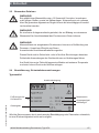
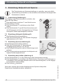
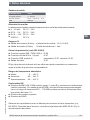
7. Adjustment of zero point and span
Only adjust the span-setting potentiometer if calibration equipment is avail-
able which has at least three times the accuracy of the pressure sensor.
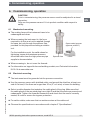
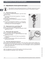
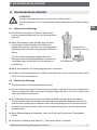
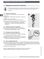
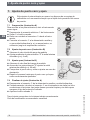
7.1 Preparation(gureA)
To gain access to the potentiometers, open the instru-
ment as follows:
■
Disconnect the electrical connection from the
instrument.
■
Remove the clamping nut .
■
Carefully pull the instrument connector from the
instrument.
■
Connect the instrument connector to the power
supply and a display unit (e.g. ammeter, voltmeter)
according to the connection diagram.
7.2 Adjustmentofzeropoint(gureB)
■
Go to the start of the measuring range.
■
Using potentiometer “Z”, adjust the minimum output
signal (e.g. 4 mA).
7.3 Settingthespan(gureB)
■
Go to the end of the measuring range.
■
Using potentiometer “S”, adjust the maximum output
signal (e.g. 20 mA).
■
Check the zero point and if there is any deviation,
re-adjust it.
■
Repeat the procedure until the zero point and the
span are set correctly.
7.4 Finishtheadjustment(gureA)
■
Disconnect the instrument connector from the power supply and the display unit.
■
Carefully push the instrument connector onto the instrument, without damaging the
wires or the seals. The seals must be clean and undamaged in order to guarantee the
given ingress protection.
■
Tighten the clamping nut .
After the adjustment, check that the system is functioning correctly.
Recommended recalibration cycle: Half-yearly
A
B

15
WIKA operating instructions pressure sensor, model HP-2
11379180.04 05/2018 EN/DE/FR/ES
EN
8. Spare part kit
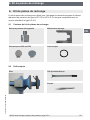
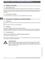
8. Spare part kit
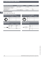
The spare part kit is used for the exchange of process connections and the bae
plate of the models HP-2-D and HP-2-E. It is not compatible with the standard version,
model HP-2-S.
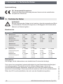
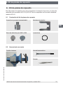
8.1 Contents of the spare part kit
8.2 Tools required
Tweezers
Torque spanner
Vice
BaeplateforDIPSorEPC O-ring
Clamping jawExchangeable process connection
DIPS EPC

16
WIKA operating instructions pressure sensor, model HP-2
11379180.04 05/2018 EN/DE/FR/ES
EN
8. Spare part kit
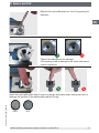
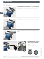
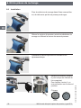
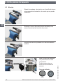
8.3 Mounting
Secure the clamping jaw in the vice as shown, so that
this cannot come loose.
Slide the pressure sensor between the clamping jaw,
using the groove milled into the process connection.
Loosen the process connection using the torque
spanner.
Dry the bae plate incl. the
O-ring using compressed air.
For access, there is a bore
on the process connection.
Bae plate
DIPS EPC

17
WIKA operating instructions pressure sensor, model HP-2
11379180.04 05/2018 EN/DE/FR/ES
EN
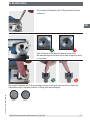
8. Spare part kit
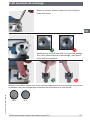
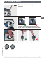
Remove the dry bae plate incl. the O-ring using the
tweezers.
Check the sealing cone for damage.
If the sealing cone is damaged, the entire instrument
must be replaced.
DIPS EPC
Insert the new bae plate with O-ring at an angle, and press down, taking care not to
damage the surface of the bae plate and the O-ring.

18
WIKA operating instructions pressure sensor, model HP-2
11379180.04 05/2018 EN/DE/FR/ES
EN
8. Spare part kit / 9. Maintenance and cleaning
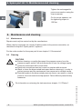
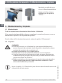
Tighten the exchangeable
process connection using the
torque spanner.
On the torque spanner, set
the tightening torque to
130 Nm.
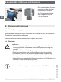
9. Maintenance and cleaning
9.1 Maintenance
Repairs must only be carried out by the manufacturer.
When a leak is suspected, as a result of hairline cracks in the process connection, as
described in chapter 8 “Spare part kit”, replace it.
For the order number for the spare part kit see chapter 12 “Accessories”
9.2 Cleaning
CAUTION!
■
Before cleaning, correctly disconnect the pressure sensor from the
pressure supply, switch it o and disconnect it from the voltage supply.
■
Clean the instrument with a moist cloth.
■
Electrical connections must not come into contact with moisture.
■
Wash or clean the dismounted instrument before returning it, in order to
protect persons and the environment from exposure to residual media.
■
Residual media in the dismounted pressure sensor can result in a risk to
persons, the environment and equipment. Take sucient precautionary
measures.
For information on returning the instrument see chapter 11.2 “Return”.

19
WIKA operating instructions pressure sensor, model HP-2
11379180.04 05/2018 EN/DE/FR/ES
EN
10. Faults
10. Faults
In the event of any faults, rst check whether the pressure sensor is mounted correctly,
mechanically and electrically.
Faults Causes Measures
No output signal Cable break Replace connecting cable
No/wrong power supply Correct the power supply
No/wrong output signal Wiring error Rectify the wiring in accordance
with the connection diagram
Constant output signal upon
change in pressure
Wrong power supply Replace instrument
Deviating output signal Zero point change through
dynamic pressure
Re-adjust zero point
Signal span too high Pressure spikes, cavitations Use instrument with cavitation and
pressure-spike protection
Signal span too small Wrong power supply Rectify the power supply
Signal span varies EMC interference sources in the
environment
Shield the instrument and cables,
remove source of interference
Instrument not grounded Ground the instrument
Strongly varying pressure of the
medium
Damping (consulting by the
manufacturer)
Leakage at the process connection Hairline crack in the pressure port Consult with manufacturer, if
required, replace instrument.
If complaint is unjustied, the handling costs will be charged.
CAUTION!
If faults cannot be eliminated by means of the measures listed above, shut
down the pressure sensor immediately, and ensure that pressure and/or
signal are no longer present, and secure the instrument from being put back
into operation inadvertently.
In this case, contact the manufacturer.
If a return is needed, please follow the instructions given in chapter
11.2 “Return”.

20
WIKA operating instructions pressure sensor, model HP-2
11379180.04 05/2018 EN/DE/FR/ES
EN
11. Dismounting, return and disposal
11. Dismounting, return and disposal
WARNING!
Residual media in the dismounted pressure sensor can result in a risk to
persons, the environment and equipment.
Take sucient precautionary measures.
11.1 Dismounting
WARNING!
Risk of burns!
Let the instrument cool down suciently before dismounting it!
During dismounting there is a risk of dangerously hot pressure media
escaping.
Only disconnect the pressure gauge once the system has been depressurised!
11.2 Return
WARNING!
Strictly observe the following when shipping the instrument:
All instruments delivered to WIKA must be free from any kind of hazardous
substances (acids, bases, solutions, etc.).
When returning the instrument, use the original packaging or a suitable transport
package.
Information on returns can be found under the heading “Service” on our local
website.
11.3 Disposal
Incorrect disposal can put the environment at risk.
Dispose of instrument components and packaging materials in an environmentally
compatible way and in accordance with the country-specic waste disposal regulations.
Seite laden ...
Seite laden ...
Seite laden ...
Seite laden ...
Seite laden ...
Seite laden ...
Seite laden ...
Seite laden ...
Seite laden ...
Seite laden ...
Seite laden ...
Seite laden ...
Seite laden ...
Seite laden ...
Seite laden ...
Seite laden ...
Seite laden ...
Seite laden ...
Seite laden ...
Seite laden ...
Seite laden ...
Seite laden ...
Seite laden ...
Seite laden ...
Seite laden ...
Seite laden ...
Seite laden ...
Seite laden ...
Seite laden ...
Seite laden ...
Seite laden ...
Seite laden ...
Seite laden ...
Seite laden ...
Seite laden ...
Seite laden ...
Seite laden ...
Seite laden ...
Seite laden ...
Seite laden ...
Seite laden ...
Seite laden ...
Seite laden ...
Seite laden ...
Seite laden ...
Seite laden ...
Seite laden ...
Seite laden ...
Seite laden ...
Seite laden ...
Seite laden ...
Seite laden ...
Seite laden ...
Seite laden ...
Seite laden ...
Seite laden ...
Seite laden ...
Seite laden ...
Seite laden ...
Seite laden ...
Seite laden ...
Seite laden ...
Seite laden ...
Seite laden ...
-
 1
1
-
 2
2
-
 3
3
-
 4
4
-
 5
5
-
 6
6
-
 7
7
-
 8
8
-
 9
9
-
 10
10
-
 11
11
-
 12
12
-
 13
13
-
 14
14
-
 15
15
-
 16
16
-
 17
17
-
 18
18
-
 19
19
-
 20
20
-
 21
21
-
 22
22
-
 23
23
-
 24
24
-
 25
25
-
 26
26
-
 27
27
-
 28
28
-
 29
29
-
 30
30
-
 31
31
-
 32
32
-
 33
33
-
 34
34
-
 35
35
-
 36
36
-
 37
37
-
 38
38
-
 39
39
-
 40
40
-
 41
41
-
 42
42
-
 43
43
-
 44
44
-
 45
45
-
 46
46
-
 47
47
-
 48
48
-
 49
49
-
 50
50
-
 51
51
-
 52
52
-
 53
53
-
 54
54
-
 55
55
-
 56
56
-
 57
57
-
 58
58
-
 59
59
-
 60
60
-
 61
61
-
 62
62
-
 63
63
-
 64
64
-
 65
65
-
 66
66
-
 67
67
-
 68
68
-
 69
69
-
 70
70
-
 71
71
-
 72
72
-
 73
73
-
 74
74
-
 75
75
-
 76
76
-
 77
77
-
 78
78
-
 79
79
-
 80
80
-
 81
81
-
 82
82
-
 83
83
-
 84
84


in anderen Sprachen
- français: WIKA HP-2 Mode d'emploi
- español: WIKA HP-2 Instrucciones de operación
Verwandte Papiere
-
WIKA IS-3 Bedienungsanleitung
-
-
-
-
-
-
-
-
WIKA S-11 Bedienungsanleitung
-
WIKA UPT-20 tag:model:UPT-21 Bedienungsanleitung