Operating instructions
Betriebsanleitung
EN
DE
Strain transducer, model F9302
Dehnungsaufnehmer, Typ F9302
Strain transducer, model F9302

2
ADPR1X914022.01 03/2019 EN/DE
Operation instructions, model F9302
EN
DE
Operating instructions model F9302 Page 3 - 22
Betriebsanleitung Typ F9302 Seite 23 - 43
© 03/2019 WIKA Alexander Wiegand SE & Co. KG
All rights reserved. / Alle Rechte vorbehalten.
WIKA
®
and tecsis
®
are registered trademarks in various countries.
WIKA
®
and tecsis
®
sind geschützte Marken in verschiedenen Ländern.
Prior to starting any work, read the operating instructions!
Keep for later use!
Vor Beginn aller Arbeiten Betriebsanleitung lesen!
Zum späteren Gebrauch aufbewahren!

3Operating instructions, model F9302
ADPR1X914022.01 03/2019 EN/DE
EN
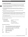
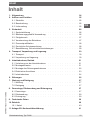
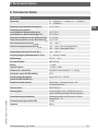
Contents
Contents
1. General information 4
2. Design and function 5
2.1 Overview. . . . . . . . . . . . . . . . . . . . . . . .5
2.2 Description . . . . . . . . . . . . . . . . . . . . . . .5
2.3 Scope of delivery . . . . . . . . . . . . . . . . . . . . .5
3. Safety 6
3.1 Explanation of symbols . . . . . . . . . . . . . . . . . . .6
3.2 Intended use . . . . . . . . . . . . . . . . . . . . . .6
3.3 Improper use . . . . . . . . . . . . . . . . . . . . . .7
3.4 Responsibility of the operator . . . . . . . . . . . . . . . . .7
3.5 Personnel qualification . . . . . . . . . . . . . . . . . . .8
3.6 Personal protective equipment . . . . . . . . . . . . . . . .8
3.7 Labelling, safety marks . . . . . . . . . . . . . . . . . . .9
4. Transport, packaging and storage 10
4.1 Transport. . . . . . . . . . . . . . . . . . . . . . . 10
4.2 Packaging and storage . . . . . . . . . . . . . . . . . . 10
5. Commissioning, operation 11
5.1 Precautions before commissioning . . . . . . . . . . . . . . 11
5.2 Mounting instructions . . . . . . . . . . . . . . . . . . 11
5.3 Installing the strain transducer . . . . . . . . . . . . . . . 12
5.4 Electrical connection . . . . . . . . . . . . . . . . . . . 13
5.5 Commissioning . . . . . . . . . . . . . . . . . . . . 14
6. Faults 16
7. Maintenance and cleaning 17
7.1 Maintenance . . . . . . . . . . . . . . . . . . . . . 17
7.2 Cleaning . . . . . . . . . . . . . . . . . . . . . . . 17
8. Dismounting, return and disposal 17
8.1 Dismounting . . . . . . . . . . . . . . . . . . . . . 17
8.2 Return. . . . . . . . . . . . . . . . . . . . . . . . 18
8.3 Disposal . . . . . . . . . . . . . . . . . . . . . . . 18
9. Specifications 19
10. Accessories 20
10.1 Cable . . . . . . . . . . . . . . . . . . . . . . . 20
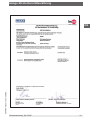
11. Appendix: EU declaration of conformity 21

4
Operating instructions, model F9302
ADPR1X914022.01 03/2019 EN/DE
EN
1. General information
1. General information
■
The strain transducer described in the operating instructions has been designed
and manufactured using state-of-the-art technology. All components are subject
to stringent quality and environmental criteria during production. Our management
systems are certified to ISO 9001.
■
These operating instructions contain important information on handling the
instrument. Working safely requires that all safety instructions and work instructions
are observed.
■
Observe the relevant local accident prevention regulations and general safety
regulations for the instrument's range of use.
■
The operating instructions are part of the product and must be kept in the immediate
vicinity of the instrument and readily accessible to skilled personnel at any time. Pass
the operating instructions on to the next operator or owner of the instrument.
■
Skilled personnel must have carefully read and understood the operating instructions
prior to beginning any work.
■
The general terms and conditions contained in the sales documentation shall apply.
■
Subject to technical modifications.
■
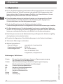
Further information:
- Internet address: www.wika.de / www.tecsis.de
- Relevant data sheet: FO 54.10
- Application consultant:
Tel.: +49 69 5806-0
Fax: +49 69 5806-7788
info@wika.de, inf[email protected]
Abbreviations, definitions
2-wire The two connection lines are used for the voltage supply.
The measuring signal also provides the supply current.
3-wire Two connection lines are used for the voltage supply.
One connection line is used for the measuring signal.
UB+ Positive power supply terminal
UB- Negative power supply terminal
S+ Positive output terminal
S- Negative output terminal
Shield Case
x-pin Pin assignment

5Operating instructions, model F9302
ADPR1X914022.01 03/2019 EN/DE
EN
2. Design and function
2. Design and function
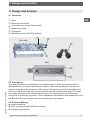
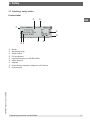
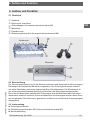
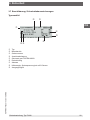
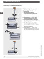
2.1 Overview
Case
Electrical connection
Protective caps for M6 Allen screws
Measuring spring
Flat gasket
Mounting screws (M6 Allen screws)
2.2 Description
The strain transducer is intended for the measurement of static and dynamic defor-
mations/strains on certain measurement objects. The strain transducer consists of a
measuring spring and a welded thin-film sensor. The measuring body is manufactured
from non-rusting stainless steel and is screwed onto the measurement object. Through
the strains occurring in the measurement object, the measuring spring of the strain
transducer is elastically deformed. These mechanical deformations are measured by the
installed thin-film sensor and output as an electrical output signal.
2.3 Scope of delivery
■
Strain transducer
■
2 M6 mounting screws (M6 Allen screws)
■
Operating instructions
Front side
Rear

6
Operating instructions, model F9302
ADPR1X914022.01 03/2019 EN/DE
EN
3. Safety
3. Safety
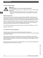
3.1 Explanation of symbols
WARNING!
... indicates a potentially dangerous situation that can result in serious
injury or death, if not avoided.
CAUTION!
... indicates a potentially dangerous situation that can result in light injuries
or damage to property or the environment, if not avoided.
Information
... points out useful tips, recommendations and information for efficient
and trouble-free operation.
3.2 Intended use
The strain transducers of the F9302 series are intended for the measurement of static
and dynamic deformations/strains on certain measurement objects.
These instruments have been designed and tested in accordance with the relevant
safety regulations for electronic measuring instruments. Any usage outside of this is
deemed to be improper. The perfect functioning and operational safety of the strain
transducers can only be guaranteed when complying with the instructions given in the
operating instructions. During its use, the legal and safety regulations (e.g. VDE 0100)
required for the particular application must additionally be observed.
This also applies accordingly when using accessories. Strain transducers are RoHS-
compliant in accordance with Directive 2011/65/EU Art. 2 (2) and (4) d), e) and g).
Faultless and safe operation of this transducer requires proper transport, professional
storage, installation and mounting as well as careful operation and corrective mainte-
nance.
The instrument has been designed and built solely for the intended use described here,
and may only be used accordingly.
The technical specifications contained in these operating instructions must be obser-
ved. Improper handling or operation of the instrument outside of its technical specifica-
tions requires the instrument to be taken out of service immediately and inspected by an
authorised service engineer.
Handle electronic precision measuring instruments with the required care (protect from

7Operating instructions, model F9302
ADPR1X914022.01 03/2019 EN/DE
EN
3. Safety
humidity, impacts, strong magnetic fields, static electricity and extreme temperatures,
do not insert any objects into the instrument or its openings). Plugs and sockets must be
protected from contamination.
The manufacturer shall not be liable for claims of any type based on operation contrary
to the intended use.
3.3 Improper use
WARNING!
Injuries through improper use
Improper use of the instrument can lead to hazardous situations and
injuries.
▶
Refrain from unauthorised modifications to the instrument.
Any use beyond or different to the intended use is considered as improper use.
3.4 Responsibility of the operator
The instrument is used in the industrial sector. The operator is therefore responsible for
legal obligations regarding safety at work.
The safety instructions within these operating instructions, as well as the safety,
accident prevention and environmental protection regulations for the application area
must be maintained.
The operator is obliged to maintain the product label in a legible condition.
To ensure safe working on the instrument, the operating company must ensure
■
that suitable first-aid equipment is available and aid is provided whenever required.
■
that the skilled electrical personnel are regularly instructed in all topics regarding
work safety, first aid and environmental protection and know the operating instruc-
tions and in particular, the safety instructions contained therein.
■
that the instrument is suitable for the particular application in accordance with its
intended use.
■
that personal protective equipment is available.

8
Operating instructions, model F9302
ADPR1X914022.01 03/2019 EN/DE
EN
3. Safety
3.5 Personnel qualification
WARNING!
Risk of injury should qualification be insufficient
Improper handling can result in considerable injury and damage to equip-
ment.
▶
The activities described in these operating instructions may only be
carried out by skilled personnel who have the qualifications described
below.
Skilled electrical personnel
Skilled electrical personnel are understood to be personnel who, based on their techni-
cal training, know-how and experience as well as their knowledge of country-specific
regulations, current standards and directives, are capable of carrying out work on
electrical systems and independently recognising and avoiding potential hazards. The
skilled electrical personnel have been specifically trained for the work environment they
are working in and know the relevant standards and regulations. The skilled electrical
personnel must comply with current legal accident prevention regulations.
Special operating conditions require further appropriate knowledge, e.g. of aggressive
media.
3.6 Personal protective equipment
The requirements for the required protective equipment result from the ambient condi-
tions at the place of use, other products or the connection to other products.
The requisite personal protective equipment must be provided by the operating compa-
ny. The operator is in no way relieved of his obligations under labour law for the safety
and the protection of workers' health.
The design of the personal protective equipment must take into account all operating
parameters of the place of use.

9Operating instructions, model F9302
ADPR1X914022.01 03/2019 EN/DE
EN
3. Safety
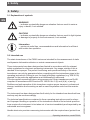
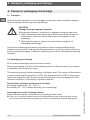
3.7 Labelling, safety marks
Product label
Model
Measuring range
Serial number
Pin assignment
Ingress protection per DIN EN 60259
Strain direction
Address
Power supply, excitation voltage for mV/V sensor
Output signal

10
Operating instructions, model F9302
ADPR1X914022.01 03/2019 EN/DE
EN
4. Transport, packaging and storage
4. Transport, packaging and storage
4.1 Transport
Check the strain transducer for any damage that may have been caused by transport.
Obvious damage must be reported immediately.
CAUTION!
Damage through improper transport
With improper transport, a high level of damage to property can occur.
▶
When unloading packed goods upon delivery as well as during inter-
nal transport, proceed carefully and observe the symbols on the
packaging.
▶
With internal transport, observe the instructions in chapter 4.2
“Packaging and storage”.
As precision measuring instruments, transducers require careful handling during
transport and mounting. Load impacts during transport (e.g. hitting a hard surface) can
lead to permanent damage, resulting in measuring errors in the subsequent measuring
operation.
4.2 Packaging and storage
Do not remove packaging until just before mounting.
Keep the packaging as it will provide optimum protection during transport (e.g. change
in installation site, sending for repair).
The measuring spring is made completely of stainless steel. The version of the accesso-
ry cables has an ingress protection of IP67. The ingress protection IP67 is only guaran-
teed in the plugged-in state. During storage the protection cap must always be on the
electrical connection to avoid entry of moisture and dirt.
Permissible conditions at the place of storage:
■
Storage temperature: -40 ... +85 °C
■
Humidity: 35 ... 85 % relative humidity (non-condensing)
Avoid exposure to the following factors:
■
Mechanical vibration, mechanical shock (putting it down hard)
■
Dust, dirt, and other objects may not be deposited in such a way that they form a
force shunt with the measuring spring, since this will falsify the measuring signal.

11Operating instructions, model F9302
ADPR1X914022.01 03/2019 EN/DE
EN
5. Commissioning, operation
5. Commissioning, operation
5.1 Precautions before commissioning
■
Strain transducers are sensitive measuring instruments and must be handled with
appropriate care.
■
The mounting surface must be even.
■
The mounting surface must be free from paint, undercoat or other coatings.
■
When making the tapped holes, care must be taken to ensure the correct hole
separation in accordance with the technical specifications.
■
Before installation, make sure that any drilling chips have been removed from the
tapped holes in the measurement object.
■
The mounting surface must be free from grease, oil and dust.
■
For an optimal measuring result, the specifications for surface roughness in the
specification documents must be followed.
5.2 Mounting instructions
CAUTION!
Damage to the instrument through improper installation
■
The installation is made on unloaded and tension-free components.
■
With the installation of the strain transducer, the installation position
and, with that, the load direction must be considered.
■
The transducer must be free from shear forces and torsion when instal-
ling. Torsional moments and shear forces cause measuring errors and
can permanently damage the transducer.
■
Do not twist the transducer.
■
During installation of the strain transducer, the output signal (strain
value) must always be monitored to avoid mechanical overload.
■
The M6 mounting screws must be tightened uniformly and with a torque
of 12 Nm.
■
After a few loadings, re-tighten
the M6 mounting screws
with 12 Nm.
■
The strain transducer may not be used as climbing aid.

12
Operating instructions, model F9302
ADPR1X914022.01 03/2019 EN/DE
EN
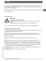
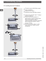
5. Commissioning, operation
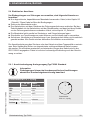
■
Loosen the protective caps using a
slotted screwdriver
■
Position the strain transducer
appropriately using the tapped holes
on the measurement object .
Tighten the strain transducer uniformly
with the M6 Allen screws with a
torque of 12 Nm.
■
Re-fit the protective caps to the
strain transducer using a slotted
screwdriver.
Protective caps for M6 Allen screws
Strain transducer
Measurement object
Mounting screws (M6 Allen screws)
5.3 Installing the strain transducer

13Operating instructions, model F9302
ADPR1X914022.01 03/2019 EN/DE
EN
5. Commissioning, operation
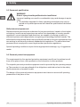
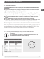
Circular connector M12 x 1, 4-pin
4 ... 20 mA
3-wire
Cable
assignment
UB+ 1 brown
UB- 3 blue
S+ 2 white
S- - -
Tare
(Com)
4 black
Shield Case
5.4 Electrical connection
To prevent interferences from coupling into the system, observe the following
information:
■
Use only shielded and low-capacitance measuring cables. For cables, see chapter
10 “Accessories”. These cables fulfil the conditions.
■
Ground the shield of the measuring cable.
■
Connect the cable shield to the case of the strain transducer. In the cables of the
accessories, the cable shield is connected by means of the knurled nut, thus connec-
ting it to the case of the strain transducer (for cables, see chapter 10 “Accessories”).
■
Do not install measuring cables in parallel to 3-phase-current cables and control
cables.
■
Stray fields from transformers, motors and contactors must be avoided.
■
Transducers, amplifiers and processing or display units must not be grounded sever-
al times. All instruments must be connected to the same protective conductor.
The pin assignment of the connector or of the cable can be found on the product label.
When using extensions, only shielded and low-capacitance cables should be used. The
permitted maximum and minimum lengths of cable are defined in ISO 11898-2. Care
should be taken also to ensure a high-quality connection of the shielding.
5.4.1 Pin assignment of analogue output, model F9302, standard
Information
Pin assignments may differ for customer-specific versions. Pay
attention to the customer release drawing!
Circular connector
M12 x 1, 4-pin

14
Operating instructions, model F9302
ADPR1X914022.01 03/2019 EN/DE
EN
5. Commissioning, operation
5.5 Commissioning
5.5.1 Commissioning the strain transducer with a factory-set span
■
The measurement object must be in an unloaded state.
■
Connect the strain transducer to the PLC controller. With this, make sure that the
control cable is connected to pin 4 (Com/Tare).
■
Set the zero point by sending the following bit signal via the PLC controller:
Bit signal Logic inputs All logic inputs
0 small input voltage (VINL) ≤ 0.4 V
1 high input voltage (VINH) ≥ 2.0 V
■
Load the measurement object up to the end of its measuring range.
■
Check whether the output signal matches with the nominal set point (end of
measuring range).
■
Unload the measurement object and check the zero signal.
■
Repeat this procedure several times in order to achieve the optimum measuring
results.
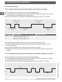
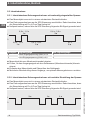
5.5.2 Commissioning the strain transducer with variable setting of the span
■
The measurement object must be in an unloaded state.
■
Connect the strain transducer to the PLC controller. With this, make sure that the
control cable is connected to pin 4 (Com/Tare).
■
Set the zero point by sending the following bit signal via the PLC controller:
0
1
0.8 s - 1.2 s
1 s
2.4 s - 3.6 s
3 s
2.4 s - 3.6 s
3 s
≥1 s
2 s
0.8 s - 1.2 s
1 s
0
1
1 s 1 s 1 s
1 s 1 s
2 s
3 s

15Operating instructions, model F9302
ADPR1X914022.01 03/2019 EN/DE
EN
5. Commissioning, operation
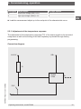
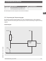
Connection diagram
■
Load the measurement object up to the end point of the characteristic curve.
5.5.3 Adjustment of the temperature response
The adjustment of the temperature response (TC) of the output signal on the mounted
component as well as the setting of the limit frequency is possible through factory
programming.
R
U=24 V
PLC
UB+
S+
F9302
COM
GND
Bit signal Logic inputs All logic inputs
0 small input voltage (VINL) ≤ 0.4 V
1 high input voltage (VINH) ≥ 2.0 V

16
Operating instructions, model F9302
ADPR1X914022.01 03/2019 EN/DE
EN
5. Commissioning, operation / 6. Faults
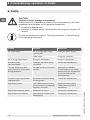
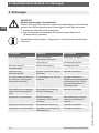
6. Faults
CAUTION!
Physical injuries, damage to equipment
If faults cannot be eliminated by means of the listed measures, the strain
transducer must be taken out of operation immediately.
▶
Contact the manufacturer.
▶
If a return is needed, please follow the instructions given in chapter 8.2
“Return”.
For contact details see chapter 1 “General information” or the back page
of the operating instructions.
Faults Causes Measures
No output signal No or wrong power supply,
current pulse
Rectify the power supply
Cable break Check the continuity
No or wrong output signal Wrong pin assignment Check pin assignment
Deviation of the
zero point signal
Overload, last offset, wrong
connection
Contact the manufacturer
Too high offset of the zero
point (over 60 % of the span)
during installation
Too high bending or torsional
moment
Interrupt the installation.
Check surface of the measu-
rement object for smoothness.
Check the setting of the
torque spanner.
Constant output signal when
changing strain
Mechanical overload, wrong
pin assignment
Contact the manufacturer
Signal span varies EMC interference sources in
the environment; for example,
frequency converter
Shield instrument; cable
shield; remove source of
interference
Signal span drops/too small Mechanical overload Contact the manufacturer
Signal span cannot be set Signal span is outside of the
setting range
Contact the manufacturer

17Operating instructions, model F9302
ADPR1X914022.01 03/2019 EN/DE
EN
7. Maintenance and cleaning / 8. Dismounting
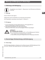
7. Maintenance and cleaning
For contact details see chapter 1 “General information” or the back page
of the operating instructions.
7.1 Maintenance
This instrument is maintenance-free.
Repairs must only be carried out by the manufacturer.
Only use original parts (see chapter 10 “Accessories”).
7.2 Cleaning
1. Prior to cleaning, disconnect the strain transducer from the voltage supply and
dismount it.
2. Clean the strain transducer with a cloth.
Electrical connections must not come into contact with moisture!
CAUTION!
Damage to the instrument
Improper cleaning may lead to damage to the instrument!
▶
Do not use any aggressive cleaning agents.
▶
Do not use any hard or pointed objects for cleaning.
8. Dismounting, return and disposal
8.1 Dismounting
Relieve the strain transducer and disconnect it from power. Loosen the mounting screws
and remove the strain transducer from the measurement object.

18
Operating instructions, model F9302
ADPR1X914022.01 03/2019 EN/DE
EN
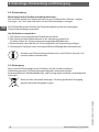
8. Dismounting, return and disposal
8.2 Return
Strictly observe the following when shipping the instrument:
All instruments delivered to WIKA must be free from any kind of hazardous substances
(acids, bases, solutions, etc.) and must therefore be cleaned before being returned.
When returning the instrument, use the original packaging or a suitable transport
packaging.
To avoid damage:
1. Wrap the instrument in an antistatic plastic film.
2. Place the instrument, along with the shock-absorbent material, in the packaging.
Place shock-absorbent material evenly on all sides of the transport packaging.
3. If possible, place a bag containing a desiccant inside the packaging.
4. Label the shipment as carriage of a highly sensitive measuring instrument.
Information on returns can be found under the heading “Service” on our
local website.
8.3 Disposal
Incorrect disposal can put the environment at risk.
Dispose of instrument components and packaging materials in an environmentally
compatible way and in accordance with the country-specific waste disposal regulations.
Do not dispose of with household waste. Ensure a proper disposal in
accordance with national regulations.

19Operating instructions, model F9302
ADPR1X914022.01 03/2019 EN/DE
EN
9. Specifications
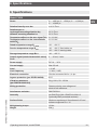
9. Specifications
Model F9302
Strain 0 … ±200 µε, 0 … ±500 µε, 0 … ±1,000 µε,
0 … ±2,000 µε
Relative linearity error d
lin
≤ ±2 % F
nom
Relative span in
unchanged mounting situation b
rg
different mounting situation b
rv
0.5 % F
nom
0.5 % F
nom
Temperature effect on the zero signal TK
0
0.1 %/10 K
Temperature effect on the characteristic
value TK
C
0.3 %/10 K
Rated temperature range B
T, nom
-20 … +80 °C
Service temperature range B
T, G
-40 … +80 °C fixed cable run
-25 … +80 °C moving cable
Storage temperature range B
T, S
-40 … +85 °C
Output signal (rated characteristic value)
C
nom
4 … 20 mA, 3-wire
Power supply DC 10 … 36 V
Current supply Max. 25 mA
Load > 10 kΩ
Limit frequency < 2 kHz (-3 dB)
Electrical connection Circular connector M12 x 1, 4-pin
Ingress protection (per IEC/EN 60529) IP67
Vibration resistance
(per DIN EN 60068-2-6)
20 g, 100 h, 50...150 Hz
Wiring protection Reverse polarity, overvoltage and
short-circuit resistance
Interference emission DIN EN 55011
Immunity per DIN EN 61326-1/DIN EN 61326-2-3
(optionally EMC-protected versions)
Surface finish Minimum requirement: Smoothness 0.05 mm/
surface roughness Rz = 16
M6 tightening torque 12 Nm
Weight 200 g

20
Operating instructions, model F9302
ADPR1X914022.01 03/2019 EN/DE
EN
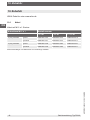
10. Accessories
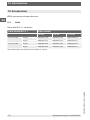
10. Accessories
WIKA accessories at www.wika.com.
10.1 Cable
Cable with M12 x 1 connector
Cable socket M12 x 1 Order number
l = 2 m l = 5 m l = 10 m
4-pin with cable straight EZE53X011010 EZE53X011012 EZE53X011016
angled EZE53X011011 EZE53X011013 EZE53X011017
5-pin with cable straight EZE53X011043 EZE53X011044 EZE53X011047
angled EZE53X011045 EZE53X011046 EZE53X011071
Other cable lengths and cable types are available on request.
Seite wird geladen ...
Seite wird geladen ...
Seite wird geladen ...
Seite wird geladen ...
Seite wird geladen ...
Seite wird geladen ...
Seite wird geladen ...
Seite wird geladen ...
Seite wird geladen ...
Seite wird geladen ...
Seite wird geladen ...
Seite wird geladen ...
Seite wird geladen ...
Seite wird geladen ...
Seite wird geladen ...
Seite wird geladen ...
Seite wird geladen ...
Seite wird geladen ...
Seite wird geladen ...
Seite wird geladen ...
Seite wird geladen ...
Seite wird geladen ...
Seite wird geladen ...
Seite wird geladen ...
-
 1
1
-
 2
2
-
 3
3
-
 4
4
-
 5
5
-
 6
6
-
 7
7
-
 8
8
-
 9
9
-
 10
10
-
 11
11
-
 12
12
-
 13
13
-
 14
14
-
 15
15
-
 16
16
-
 17
17
-
 18
18
-
 19
19
-
 20
20
-
 21
21
-
 22
22
-
 23
23
-
 24
24
-
 25
25
-
 26
26
-
 27
27
-
 28
28
-
 29
29
-
 30
30
-
 31
31
-
 32
32
-
 33
33
-
 34
34
-
 35
35
-
 36
36
-
 37
37
-
 38
38
-
 39
39
-
 40
40
-
 41
41
-
 42
42
-
 43
43
-
 44
44


in anderen Sprachen
- English: WIKA F9302 Operating instructions
Verwandte Artikel
-
WIKA F9204 Bedienungsanleitung
-
-
-
-
-
-
-
-
-