
EN
DE
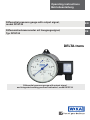
Operating instructions
Betriebsanleitung
DELTA-trans
Dierential pressure gauge with output signal
and integrated working pressure indication, model DPGT40
Dierential pressure gauge with output signal,
model DPGT40
Dierenzdruckmanometer mit Ausgangssignal,
Typ DPGT40

EN
DE
2
14093267.04 07/2017 EN/DE
WIKA operating instructions dierential pressure gauge, model DPGT40
© 2014 WIKA Alexander Wiegand SE & Co. KG
All rights reserved. / Alle Rechte vorbehalten.
WIKA
®
is a registered trademark in various countries.
WIKA
®
ist eine geschützte Marke in verschiedenen Ländern.
Prior to starting any work, read the operating instructions!
Keep for later use!
Vor Beginn aller Arbeiten Betriebsanleitung lesen!
Zum späteren Gebrauch aufbewahren!
Operating instructions, model DPGT40 Page 3 - 20
Betriebsanleitung, Typ DPGT40 Seite 21 - 37

EN
WIKA operating instructions dierential pressure gauge, model DPGT40 3
14093267.04 07/2017 EN/DE
Contents
1. General information 4
2. Safety 5
3. Specications 8
4. Design and function 11
5. Transport, packaging and storage 12
6. Commissioning, operation 13
7. Options and accessories 17
8. Maintenance 18
9. Dismounting, return and disposal 19
Appendix: Declarations of conformity 38
Contents
Declarations of conformity can be found online at www.wika.com.

EN
WIKA operating instructions dierential pressure gauge, model DPGT404
14093267.04 07/2017 EN/DE
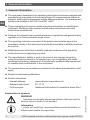
1. General information
■
The instrument described in the operating instructions have been designed and
manufactured using state-of-the-art technology. All components are subject to
stringent quality and environmental criteria during production. Our management
systems are certied to ISO 9001 and ISO 14001.
■
These operating instructions contain important information on handling the
instrument. Working safely requires that all safety instructions and work
instructions are observed.
■
Observe the relevant local accident prevention regulations and general safety
regulations for the instrument's range of use.
■
The operating instructions are part of the product and must be kept in the
immediate vicinity of the instrument and readily accessible to skilled personnel
at any time.
■
Skilled personnel must have carefully read and understood the operating
instructions prior to beginning any work.
■
The manufacturer's liability is void in the case of any damage caused by
using the product contrary to its intended use, non-compliance with these
operating instructions, assignment of insuciently qualied skilled personnel
or unauthorised modications to the instrument.
■
The general terms and conditions contained in the sales documentation shall
apply.
■
Subject to technical modications.
■
Further information:
- Internet address: www.wika.de / www.wika.com
- Relevant data sheet: PV 17.19
- For Ex version: Additional Information for hazardous areas (Ex i)
1. General information
Explanation of symbols
WARNING!
... indicates a potentially dangerous situation that can result in
serious injury or death, if not avoided.
Information
... points out useful tips, recommendations and information for
ecient and trouble-free operation.

EN
WIKA operating instructions dierential pressure gauge, model DPGT40 5
14093267.04 07/2017 EN/DE
2. Safety
2. Safety
WARNING!
Before installation, commissioning and operation, ensure that
the appropriate instrument has been selected in terms of design
and specic measuring conditions.
Check the compatibility with the medium of the materials
subjected to pressure!
In order to guarantee the measuring accuracy and long-term
stability specied, the corresponding load limits must be
observed.
Only work on the gauge with the voltage disconnected.
Non-observance can result in serious injury and/or damage to
the equipment.
Information
Further important safety instructions can be found in the
individual chapters of these operating instructions.
2.1 Intended use
The dierential pressure measuring instruments of the DELTA-line product family
are primarily used for the monitoring of low dierential pressures where there are
high requirements in terms of one-sided overpressure and static pressure.
Typical markets for these products are the shipbuilding industry, process heating
technology, the heating, ventilation and air-conditioning industries, the water/
wastewater industry, and machine building and plant construction. For these,
the main function of the measuring instruments is the monitoring of lters,
compressors and pumps.
The instrument has been designed and built solely for the intended use described
here, and may only be used accordingly.
The manufacturer shall not be liable for claims of any type based on operation
contrary to the intended use.

EN
WIKA operating instructions dierential pressure gauge, model DPGT406
14093267.04 07/2017 EN/DE
2.2 Personnel qualication
WARNING!
Risk of injury should qualication be insucient!
Improper handling can result in considerable injury and damage
to equipment.
■
The activities described in these operating instructions
may only be carried out by skilled personnel who have the
qualications described below.
Skilled personnel
Skilled personnel are understood to be personnel who, based on their technical
training, knowledge of measurement and control technology and on their
experience and knowledge of country-specic regulations, current standards
and directives, are capable of carrying out the work described and independently
recognising potential hazards.
2. Safety
2.3 Special hazards
WARNING!
For hazardous media such as oxygen, acetylene, ammable or
toxic gases or liquids, and refrigeration plants, compressors, etc.,
in addition to all standard regulations, the appropriate existing
codes or regulations must also be followed.
WARNING!
Residual media in dismounted measuring instruments can result
in a risk to persons, the environment and equipment.
Take sucient precautionary measures.

EN
WIKA operating instructions dierential pressure gauge, model DPGT40 7
14093267.04 07/2017 EN/DE
2. Safety
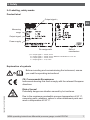
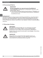
2.4 Labelling, safety marks
Product label
Explanation of symbols
Before mounting and commissioning the instrument, ensure
you read the operating instructions!
CE, Communauté Européenne
Instruments bearing this mark comply with the relevant European
directives.
Date of
manufacture
Pin assignment
Output signal
Measuring
range
Power supply
Output signal
1)
1) A = output signal 4 ... 20 mA, 2-wire
E = output signal 4 ... 20 mA, 2-wire, ATEX Ex II 2G Ex ib IIC T4 / T5 / T6
B = output signal 0 ... 20 mA, 3-wire
F = output signal 0 ... 10 V, 3-wire
Risk of burns!
Potentially dangerous situation caused by hot surfaces.
Due to the maximum permissible process temperature of 90 °C,
measuring cells, adapters, valves or other attachment parts can
reach a temperature of 90 °C.

EN
WIKA operating instructions dierential pressure gauge, model DPGT408
14093267.04 07/2017 EN/DE
3. Specications
3. Specications
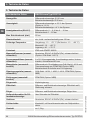
Mechanical data DELTA-trans model DPGT40
Nominal size Dierential pressure indication: Ø 100 mm
Working pressure indication: Ø 22 mm
Accuracy Dierential pressure indication: ≤ 2.5 % of span
(option ≤ 1.6 %)
Working pressure indication: ≤ 4 % of span
Scale ranges (EN 837) Dierential pressure: 0 ... 0.16 to 0 ... 10 bar
Working pressure: 0 ... 25 bar
Max. working pressure (stat.) 25 bar
Overpressure safety Either side max. 25 bar
Permissible temperature Ambient: -10 ... +70 °C (Ex version: -10 ... +60 °C)
Medium: -10 ... +90 °C
Storage: -40 ... +70 °C
Ingress protection IP65 per EN /IEC 60529
Media chamber (wetted) Aluminium, EN AC–Al Si9Cu3(Fe), black lacquered
(option: Stainless steel 1.4571)
Process connections (wetted) 2 x G 1/4 female, lower mount, in-line, centre dis-
tance 26 mm
Pressure elements (wetted) Dierential pressure: Compression springs from
stainless steel 1.4310 and separating diaphragm
from FPM/FKM (option: NBR)
Working pressure: Bourdon tube from Cu-alloy
Transmission parts (wetted) Stainless steel 1.4301, 1.4305, 1.4310, FPM/FKM
(option: NBR)
Sealings (wetted) FPM/FKM (option: NBR)
Movement Copper alloy
Dial Dierential and working pressure indication: White
dial, black lettering
Pointer Dierential and working pressure indication: Blue
pointer
Zero adjustment for dierential
pressure indication
Via screw in the dial
Case Aluminium, EN AC–Al Si9Cu3(Fe), black lacquered
Window Plastic, with plug screw for zero adjustment
Weight approx. 1.3 kg

EN
WIKA operating instructions dierential pressure gauge, model DPGT40 9
14093267.04 07/2017 EN/DE
3. Specications
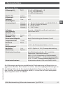
As a power supply, an unstabilised DC power supply is sucient in the range of
the specied limits. It is important to ensure that the applied power supply is at
least greater than the maximum required voltage drop from the external display
and evaluation units; i.e. the voltage at the instrument must not fall below 10 V.
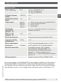
Electrical data
Power supply U
B
DC V 12 < U
B
≤ 30 (Variant 1 + 3)
14 < U
B
≤ 30 (Variant 2)
15 < U
B
≤ 30 (Variant 4)
Inuence of power
supply
% FS/10 V
≤ 0.1
Permissible residual
ripple
% ss ≤ 10
Output signal Variant 1
Variant 2
Variant 3
Variant 4
4 … 20 mA, 2-wire, passive, per NAMUR NE 43
4 … 20 mA, 2-wire, Ex version
0 ... 20 mA, 3-wire
0 ... 10 V, 3-wire
Permissible
max. load R
A
(variant 1 - 3)
R
A
≤ (U
B
- 12 V)/0.02 A with R
A
in Ω and U
B
in V,
however max. 600 Ω
Eect of load
(variant 1 - 3)
% FS ≤ 0.1
Electrical zero point Through a jumper across terminals 5 and 6
Long-term stability
of electronics
% FS/a < 0.3
Electr. output signal ≤ 2.5 % of measuring span (option ≤ 1.6 %)
Linear error % of span ≤ 2.5 % (option ≤ 1.6 %), terminal method
Electrical connection Via angular connector, 180° rotatable,
wire protection, cable gland M20 x 1.5,
incl. strain relief, connection cable: Outer
diameter 7 ... 13 mm, conductor cross-
section 0.14 ... 1.5 mm
2
, temperature resistance
up to 70 °C
Wiring protection Angular connector: IP65 per EN/IEC 60529

EN
WIKA operating instructions dierential pressure gauge, model DPGT4010
14093267.04 07/2017 EN/DE
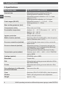
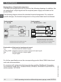
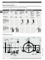
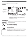
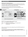
Designation of terminal connectors
The exact pin assignments can be found in the following drawings. In addition, the
pin assignment, output signal and the required power supply are stated on the
product label.
The following diagram shows the standard terminal assignment. For customer-
specic designs, the terminal assignment on the product label must be followed.
2-wire system
4 … 20 mA
3-wire system
0 … 20 mA and 0 ... 10 V
U
B
+/I+
0 V/GND
Evaluation
(display)
This connection must not be used for
equipotential bonding. The instrument
must be incorporated in the equipotential
bonding via the process connection.
Terminals 3 and 4: for internal use only
Terminals 5 and 6: reset zero point
Evaluation
(display)
Power supply
Power supply
Explanation of the terminal assignments used:
U
B
+ Positive terminal of power supply
0 V/Sig-/GND Negative terminal of power supply and output signal
Sig+ Positive terminal of output signal
I+ Output signal
0 V/Sig-/GND
U
B
+
Sig+
Do not use this
terminal
Do not use this
terminal
3. Specications
For further specications see the corresponding product label, WIKA data sheet
and order documentation.
For versions with optional explosion protection read the “Additional information
for hazardous areas (Ex i), models DPS40, DPGS40, DPGS40TA und DPGT40”,
article number 14110818.

EN
WIKA operating instructions dierential pressure gauge, model DPGT40 11
14093267.04 07/2017 EN/DE
4. Design and function
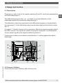
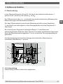
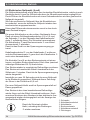
4.1 Description
4. Design and function
Pressures p
1
and p
2
act on the media chambers ⊕ and ⊖, which are separated by
an elastic diaphragm .
The dierential pressure (Δp = p
1
- p
2
) leads to an axial deection of the
diaphragm against the measuring range springs .
The deection, which is proportional to the dierential pressure, is transmitted to
the movement in the indicating case via a pressure-tight and low friction rocker
arm .
A magnet , xed to the rear of the movement, aects the electromagnetic eld of
the HALL sensor. The signal that results from this is converted to a standardised
current output signal by the signal conditioning board .
Overpressure safety is provided by metal bolsters resting against the elastic
diaphragm.
14077606.01
⊖ ⊕
4.2 Scope of delivery
Cross-check scope of delivery with delivery note.

EN
WIKA operating instructions dierential pressure gauge, model DPGT4012
14093267.04 07/2017 EN/DE
5. Transport, packaging and storage
5. Transport, packaging and storage
5.1 Transport
Check the instrument for any damage that may have been caused by transport.
Obvious damage must be reported immediately.
5.2 Packaging
Do not remove packaging until just before mounting.
Keep the packaging as it will provide optimum protection during transport (e.g.
change in installation site, sending for repair).
5.3 Storage
Permissible conditions at the place of storage
Storage temperature: -40 ... +70 °C
In order to prevent damage, the following points should be noted for the
storage of the instruments:
■
Leave the instruments in their original packaging
■
Following any possible removal of the measuring instruments, e.g. for testing,
the instrument should again be stored in its original packaging
Avoid exposure to the following factors:
■
Direct sunlight or proximity to hot objects
■
Mechanical vibration, mechanical shock (putting it down hard)
■
Soot, vapour, dust, humidity and corrosive gases
■
Potentially explosive environments, ammable atmosphere
WARNING!
Before storing the instrument, any residual media must be
removed. This is of particular importance if the medium
is hazardous to health, e.g. caustic, toxic, carcinogenic,
radioactive, etc.

EN
WIKA operating instructions dierential pressure gauge, model DPGT40 13
14093267.04 07/2017 EN/DE
6. Commissioning, operation
6. Commissioning, operation
6.1 Mechanical connection
■
In accordance with the general technical regulations for pressure gauges (e.g.
EN 837-2 “Selection and installation recommendations for pressure gauges”).
■
Mounting of the pressure connections according to axed symbols, ⊕ high
pressure, ⊖ low pressure
■
Mounting by means of:
- rigid measuring line or
- wall mounting with available mounting links
■
Process connections 2 x G 1/4 female, lower mount (LM), in-line, centre
distance 26 mm, operating position NL 90 (nominal position) per DIN 16257
(i.e. vertical dial), design the threads of the pressure connection in accordance
with EN 837-3 (section 7.3.2).
■
Prior to the installation of the instrument, clean the measuring lines thoroughly
by tapping and blowing or rinsing
■
Protect measuring instruments from contamination and high temperature
changes!
■
The instrument must be mounted free from vibration and should be aligned so
that it is easy to read. It is recommended that an isolation device is interposed
between the pressure tapping point and the pressure gauge, which will en-
able the replacement of the instrument and a zero point check while the plant
is running. The instruments should be protected against coarse dirt and wide
uctuations in ambient temperature.
■
Correct sealing of the connections must be made using suitable at gaskets,
sealing rings or WIKA prole sealings. In order to orientate the gauge so that
the on-site display can be read as well as possible, a clamp socket or union
nut should be used. When screwing on and unscrewing the instruments they
should not be gripped by the case, but rather only on the spanner ats of the
connection!
Wall mounting
Mounting using three integrally cast mounting lugs

EN
WIKA operating instructions dierential pressure gauge, model DPGT4014
14093267.04 07/2017 EN/DE
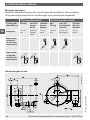
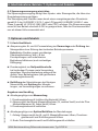
Measuring assemblies
Proven measuring assemblies for various types of media. The assemblies that are
particularly recommended for use are shown below.
6. Commissioning, operation
14078303.01
Dimensions in mm
Liquid media Gaseous media
Filling of the
measuring
line
liquid liquid
with
vapour
complete-
ly vapour-
ised
gase-
ous
partially
con-
densed
(damp)
com-
pletely
con-
densed
Examples
conden-
sate
boiling
liquids
“liquid
gases”
dry air moist air
ue gases
steam
Pressure
gauge above
the tapping
point
Pressure
gauge below
the tapping
point

EN
WIKA operating instructions dierential pressure gauge, model DPGT40 15
14093267.04 07/2017 EN/DE
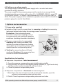
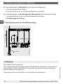
Measuring assemblies
The preferred measuring assemblies for various possible applications are
specied in DIN 19216.
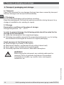
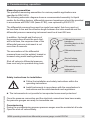
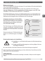
The following schematic diagram shows a recommended assembly for liquid
media. As throttling devices, dierential pressure transducers should be provided
in accordance with DIN 1952 (issue 07.82), now replaced by EN 5167/1.
The dierential pressure lines must be made from metal, their bore must not
be less than 4 mm and the eective length between the valve manifold and the
dierential pressure measuring instrument must be at least 500 mm.
Dierential pressure
transducer
(throttling device in the
process line)
Dierential pressure
instrument
(DELTA-trans)
Shut-o valves
(valve manifold)
Dierential pressure
line
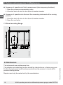
6. Commissioning, operation
In addition, the length and the bore of
the pressure lines should be such that,
with cold lines, the response time of the
dierential pressure instrument is not
more than 5 seconds.
The connections of the dierential
pressure lines must be welded, brazed or
screwed using metal sealing elements.
Shut-o valves in dierential pressure
lines must only be operated using tools.
Safety instructions for installation
■
Follow the installation and safety instructions within the
operating instructions.
■
Install instruments in accordance with the manufacturer's
instructions and the valid standards and regulations.
■
The instruments do not provide for incorporated overcurrent protectors!
Once the pressure connection and the electrical connections have been made,
the pressure gauges are ready for immediate use.
Commissioning
During the commissioning process pressure surges must be avoided at all costs.
Open the shut-o valves slowly.

EN
WIKA operating instructions dierential pressure gauge, model DPGT4016
14093267.04 07/2017 EN/DE
6. Commissioning, operation
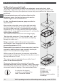
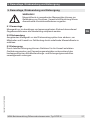
6.2 Electrical zero point (4 mA)
The zero point adjustment is made by an adjustment screw in the front, which,
depending on the instrument model, is accessible by loosening the window or the
locking screw. By turning the adjustment screw using a screwdriver the desired zero
point is set.
If the mechanical zero point has been altered via the
adjustment screw, the electrical zero point must be
matched again to the mechanical one.
For this, the dierential pressure gauge must rst be
depressurised.
Remove the entire cable cover on the right-hand side
of the instrument. To do this, undo the screw on the
top of the cable cover cap completely with a slotted
screwdriver (0.6 x 3.5 mm). Remove the screw. Pull the
cable cover , along with the socket insert , out from the
cable socket baseplate .
This isolates the instrument from the voltage supply.
Take the cable cover cap from the cable cap and
push the socket insert out, downwards, completely
through the cable cap .
Bridge contacts 5 and 6 on the socket insert with a
short length of wire, stripped at both ends (maximum
permissible resistance 30 Ω).
Reassemble the connector in the reverse order. Insert the
connector, with the piece of wire mounted, into the pin
insert . This remakes the voltage supply.
Within a max. of 30 seconds, the new zero point will be
saved within the electronics. During this time, the current in
the loop will rise to 9.5 mA.
The new zero point is maintained, even with a loss of
power, for an extended period.
Once more, disconnect the connector in the order
described above and remove the piece of wire. After again
assembling the connector, the electrical output signal will
once more match the display of the mechanical pointer.
Screw
Cable cover cap
Cable cover
Socket insert
Cable socket baseplate
Sealings
In order that the ingress
protection is maintained, the
seals must be retted.

EN
WIKA operating instructions dierential pressure gauge, model DPGT40 17
14093267.04 07/2017 EN/DE
6. Commissioning, operation / 7. Options and accessories
6.3 Setting up a voltage supply
The voltage supply is made via a power supply unit or a control unit which
provides the energy limitation.
The power supply for the pressure gauge must be made via an energy-limited
electrical circuit in accordance with section 9.3 of UL/EN/IEC 61010-1, or an LPS
to UL/EN/IEC 60950-1, or class 2 in accordance with UL1310/UL1585 (NEC or
CEC). The power supply must be suitable for operation above 2,000 m should the
pressure gauge be used at this altitude.
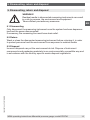
7. Options and accessories
7.1 4-way valve manifold
■
Isolation of the ⊕ and ⊖ process lines for removing or testing the measuring
instrument without interrupting the running process operation.
Protection of the instrument against
excessive overpressure loading, such as
in pressure tests and undened operating
conditions (including intermittent shutdown).
■
Pressure compensation for zero point
checking with running processes, and
avoiding one-sided overpressure loading
during start-up and operation phases (with
opened pressure compensating valve).
■
Venting the measuring lines with liquid
media and ushing of the measuring lines,
in order to remove contamination.
Vent valve
Shut-o valve
⊖ side
Shut-o valve
⊕ side
Pressure
compensating valve
Specications for handling
■
Sequence of operations to start measurement
1. Open the pressure compensating valve (middle valve spindle)
2. Open the shut-o valve for the negative media chamber (⊖, right-hand valve)
and the positive media chamber (⊕, left-hand valve)
3. Close the pressure compensating valve
■
Sequence of operations to ush/vent the measuring lines
1. Start: Open the shut-o valve for the ⊕ and ⊖ media chamber, open the
pressure compensating valve and vent valve
2. Finish: Close the pressure compensating valve and vent valve

EN
WIKA operating instructions dierential pressure gauge, model DPGT4018
14093267.04 07/2017 EN/DE
7. Options and accessories / 8. Maintenance
■
Sequence of operations to nish measurement (also temporary shutdown)
1. Open the pressure compensating valve
2. Close the shut-o valve for the ⊕ and ⊖ media chamber
■
Sequence of operations to dismount the measuring instrument with a running
process
1. Close the shut-o valve for the ⊕ and ⊖ media chamber
2. Open the vent valve
7.2 Panel mounting ange
14078276.01
Panel
Cutout
8. Maintenance
The instruments are maintenance-free.
The indicator and switching function should be checked once or twice every year.
For this the instrument must be disconnected from the process to check with a
pressure testing device.
Repairs must only be carried out by the manufacturer.

EN
WIKA operating instructions dierential pressure gauge, model DPGT40 19
14093267.04 07/2017 EN/DE
9. Dismounting, return and disposal
9. Dismounting, return and disposal
WARNING!
Residual media in dismounted measuring instruments can result
in a risk to persons, the environment and equipment.
Take sucient precautionary measures.
9.1 Dismounting
Only disconnect the measuring instrument once the system has been depressur-
ised and the power disconnected!
If necessary, the measuring line must have strain relief.
9.2 Return
Wash or clean the dismounted measuring instrument before returning it, in order
to protect personnel and the environment from exposure to residual media.
9.3 Disposal
Incorrect disposal can put the environment at risk. Dispose of instrument
components and packaging materials in an environmentally compatible way and
in accordance with the country-specic waste disposal regulations.

EN
WIKA operating instructions dierential pressure gauge, model DPGT4020
14093267.04 07/2017 EN/DE
Seite laden ...
Seite laden ...
Seite laden ...
Seite laden ...
Seite laden ...
Seite laden ...
Seite laden ...
Seite laden ...
Seite laden ...
Seite laden ...
Seite laden ...
Seite laden ...
Seite laden ...
Seite laden ...
Seite laden ...
Seite laden ...
Seite laden ...
Seite laden ...
Seite laden ...
Seite laden ...
-
 1
1
-
 2
2
-
 3
3
-
 4
4
-
 5
5
-
 6
6
-
 7
7
-
 8
8
-
 9
9
-
 10
10
-
 11
11
-
 12
12
-
 13
13
-
 14
14
-
 15
15
-
 16
16
-
 17
17
-
 18
18
-
 19
19
-
 20
20
-
 21
21
-
 22
22
-
 23
23
-
 24
24
-
 25
25
-
 26
26
-
 27
27
-
 28
28
-
 29
29
-
 30
30
-
 31
31
-
 32
32
-
 33
33
-
 34
34
-
 35
35
-
 36
36
-
 37
37
-
 38
38
-
 39
39
-
 40
40


in anderen Sprachen
- English: WIKA DPGT40 Operating instructions
Verwandte Papiere
-
WIKA DELTA-plus DPG40 Bedienungsanleitung
-
-
-
-
-
-
-
-
-
