
Operating instructions
Betriebsanleitung
EN
DE
Pressure gauges NS 63 with Reed contact
model 851-A, for hazardous areas
Manometer NG 63 mit Reed-Kontakt Typ 851-A,
für explosionsgefährdete Bereiche

2
11041781.04 01/2020 EN/DE
Pressure gauge with reed contact model 851-A, for Ex areas
EN
DE
© 04/2005 WIKA Alexander Wiegand SE & Co. KG
All rights reserved. / Alle Rechte vorbehalten.
WIKA
®
is a registered trademark in various countries.
WIKA
®
ist eine geschützte Marke in verschiedenen Ländern.
Prior to starting any work, read the operating instructions!
Keep for later use!
Vor Beginn aller Arbeiten Betriebsanleitung lesen!
Zum späteren Gebrauch aufbewahren!
Operating instructions for model 232.3x.063
with model 851-A for hazardous areas
Page 3 - 36
Betriebsanleitung für Typ 232.3x.063 mit
Typ 851-A für explosionsgefährdete Bereiche
Seite 37 - 70

3
11041781.04 01/2020 EN/DE
Pressure gauge with reed contact model 851-A, for Ex areas
EN
Content
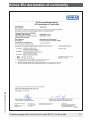
Declarations of conformity can be found online at www.wika.com
1. General information 4
2. Design and function 5
2.1 Overview . . . . . . . . . . . . . . . . . . . . . . . . . . 5
2.2 Description. . . . . . . . . . . . . . . . . . . . . . . . . 5
2.3 Scope of delivery . . . . . . . . . . . . . . . . . . . . . 6
3. Safety 7
3.1 Explanation of symbols . . . . . . . . . . . . . . . . . . 7
3.2 Intended use. . . . . . . . . . . . . . . . . . . . . . . . 8
3.3 Improper use. . . . . . . . . . . . . . . . . . . . . . . . 8
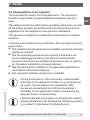
3.4 Responsibility of the operator . . . . . . . . . . . . . . 9
3.5 Personnel qualification . . . . . . . . . . . . . . . . . .10
3.6 Skilled personnel . . . . . . . . . . . . . . . . . . . . . 10
3.7 Labelling, safety marks . . . . . . . . . . . . . . . . . . 11
3.8 Ex marking . . . . . . . . . . . . . . . . . . . . . . . . .12
3.9 Specifications and temperature limits . . . . . . . . . . 12
3.10 Special conditions for safe use (X conditions) . . . . . 14
4. Transport, packaging and storage 15
4.1 Transport . . . . . . . . . . . . . . . . . . . . . . . . . .15
4.2 Packaging and storage . . . . . . . . . . . . . . . . . . 15
5. Commissioning, operation 16
5.1 Mechanical connection . . . . . . . . . . . . . . . . . . 17
5.2 Electrical connection . . . . . . . . . . . . . . . . . . . 23
5.3 Contact protection measures. . . . . . . . . . . . . . .25
5.4 Commissioning . . . . . . . . . . . . . . . . . . . . . . 26
6. Faults 26
7. Maintenance and cleaning 29
7.1 Maintenance. . . . . . . . . . . . . . . . . . . . . . . .29
7.2 Cleaning . . . . . . . . . . . . . . . . . . . . . . . . . . 30
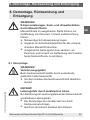
8. Dismounting, return and disposal 31
8.1 Dismounting . . . . . . . . . . . . . . . . . . . . . . . . 31
8.2 Return . . . . . . . . . . . . . . . . . . . . . . . . . . . 32
8.3 Disposal . . . . . . . . . . . . . . . . . . . . . . . . . . 33
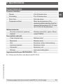
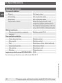
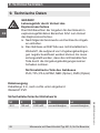
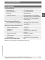
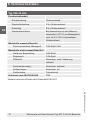
9. Specications 34
Annex: EU declaration of conformity 71

4
11041781.04 01/2020 EN/DE
Pressure gauge with reed contact model 851-A, for Ex areas
EN
1. General information
1. General information
■
The contact pressure gauge described in the operating
instructions has been designed and manufactured using
state-of-the-art technology. All components are subject to
stringent quality and environmental criteria during produc-
tion. Our management systems are certified to ISO 9001
and ISO 14001.
■
These operating instructions contain important information on
handling the instrument. Working safely requires that all safety
instructions and work instructions are observed.
■
Observe the relevant local accident prevention regulations and
general safety regulations for the instrument's range of use.
■
The operating instructions are part of the product and must
be kept in the immediate vicinity of the instrument and readily
accessible to skilled personnel at any time.
■
Skilled personnel must have carefully read and understood the
operating instructions prior to beginning any work.
■
The manufacturer's liability is void in the case of any damage
caused by using the product contrary to its intended use,
non-compliance with these operating instructions, assignment
of insufficiently qualified skilled personnel or unauthorised
modifications to the instrument.
■
The general terms and conditions contained in the sales
documentation shall apply.
■
Subject to technical modifications.
■
Further information:
- Internet address: www.wika.de / www.wika.com
- Relevant data sheet:
PV 22.03 (model PGS23.063)
PM 02.11 (model 232.35.063)

5
11041781.04 01/2020 EN/DE
Pressure gauge with reed contact model 851-A, for Ex areas
EN
2. Design and function
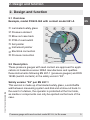
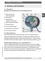
2.1 Overview
Example, model PGS23.063 with contact model 851-A
Laminated safety glass
Pressure element
Blow-out case back
PCB of reed switch
Set pointer
Instrument pointer
Electrical connection
Process connection
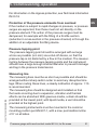
2.2 Description
These pressure gauges with reed contact are approved for appli-
cations in hazardous areas. WIKA manufactures and qualifies
these instruments following EN 837-1 (pressure gauges) and DIN
16085 (switch contacts) in the safety version “S3”.
Safety version “S3” per EN 837-1
This version is made up of laminated safety glass, a solid baffle
wall between measuring system and dial and a blow-out back. In
the event of a failure, the operator is protected at the front side,
as media or components can only be ejected via the back of the
case.
2. Design and function

6
11041781.04 01/2020 EN/DE
Pressure gauge with reed contact model 851-A, for Ex areas
EN
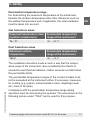
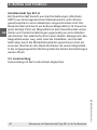
Switch contact model 851-A
A reed contact consists of three contact tongues (change-over
contact, SPDT), made of a ferromagnetic material, which are
fused in a glass body under an inert gas atmosphere. The reed
contact is actuated by an external magnetic field (e.g. permanent
magnet). If a magnetic field passes the reed contact, both contact
tongues attract each other and close the contact. The electrical
current can flow. If the magnetic field moves away, the field
strength drops, but the contact remains closed through the bista-
bility. Only a new traverse of the reed contact with a magnetic field
in the opposite direction opens the two contact tongues again.
2.3 Scope of delivery
Cross-check scope of delivery with delivery note.
2. Design and function

7
11041781.04 01/2020 EN/DE
Pressure gauge with reed contact model 851-A, for Ex areas
EN
3. Safety
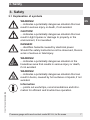
3.1 Explanation of symbols
WARNING!
... indicates a potentially dangerous situation that can
result in serious injury or death, if not avoided.
CAUTION!
... indicates a potentially dangerous situation that can
result in light injuries or damage to property or the
environment, if not avoided.
DANGER!
... identifies hazards caused by electrical power.
Should the safety instructions not be observed, there is
a risk of serious or fatal injury.
WARNING!
... indicates a potentially dangerous situation in the
hazardous area that results in serious injury or death,
if not avoided.
WARNING!
... indicates a potentially dangerous situation that can
result in burns, caused by hot surfaces or liquids, if not
avoided.
Information
... points out useful tips, recommendations and infor-
mation for efficient and trouble-free operation.
3. Safety

8
11041781.04 01/2020 EN/DE
Pressure gauge with reed contact model 851-A, for Ex areas
EN
3.2 Intended use
These instruments are used to control process values and to
monitor plants in industrial applications. The contact pressure
gauge with model 851-A reed contact(s) displays the process
pressure on site and opens/closes circuits at defined pressure
values.
The instrument offers many application possibilities for gaseous
and liquid aggressive media that are not highly viscous or
crystallising.
Only use the instrument in applications that lie within
its technical performance limits (e.g. temperature limits,
material compatibility, ...).
→ For performance limits see chapter 9 “Specifications”.
The instrument has been designed and built solely for the intend-
ed use described here, and may only be used accordingly.
The manufacturer shall not be liable for claims of any type based
on operation contrary to the intended use.
3.3 Improper use
WARNING!
Injuries through improper use
Improper use of the instrument can lead to hazardous
situations and injuries.
▶
Refrain from unauthorised modifications to the
instrument.
▶
Do not use the instrument with abrasive or viscous
media.
Any use beyond or different to the intended use is considered as
improper use.
3. Safety

9
11041781.04 01/2020 EN/DE
Pressure gauge with reed contact model 851-A, for Ex areas
EN
3.4 Responsibility of the operator
The instrument is used in the industrial sector. The operator is
therefore responsible for legal obligations regarding safety at
work.
The safety instructions within these operating instructions, as well
as the safety, accident prevention and environmental protection
regulations for the application area must be maintained.
The operator is obliged to maintain the product label in a legible
condition.
To ensure safe working on the instrument, the operating company
must ensure
■
that suitable first-aid equipment is available and aid is provided
whenever required.
■
that the operating personnel are regularly instructed in all
topics regarding work safety, first aid and environmental
protection and know the operating instructions and, in particu-
lar, the safety instructions contained therein.
■
that the instrument is suitable for the particular application in
accordance with its intended use.
■
that personal protective equipment is available.
On the wetted parts of the instrument, small residual
amounts of the adjustment medium (e.g. compressed
air, water, oil) can adhere from production. With
increased requirements for technical cleanliness,
suitability for the application must be checked by the
operator before commissioning.
Liquid media with the property of changing the volume
during solidification can damage the measuring system
(e.g. water if it falls below the freezing point).
3. Safety

10
11041781.04 01/2020 EN/DE
Pressure gauge with reed contact model 851-A, for Ex areas
EN
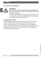
3.5 Personnel qualification
WARNING!
Risk of injury should qualification be insufficient!
Improper handling can result in considerable injury and
damage to property.
The activities described in these operating instructions
may only be carried out by skilled personnel who have
the qualifications described below.
3.6 Skilled personnel
Skilled personnel are understood to be personnel who, based
on their technical training, knowledge of measurement and
control technology and on their experience and knowledge of
country-specific regulations, current standards and directives, are
capable of carrying out the work described and independently
recognising potential hazards.
3. Safety

11
11041781.04 01/2020 EN/DE
Pressure gauge with reed contact model 851-A, for Ex areas
EN
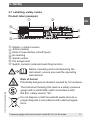
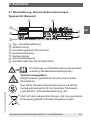
3.7 Labelling, safety marks
Product label (example)
Model + contact version
Article number
Date of manufacture (month/year)
Ex marking
Serial number
Pin assignment
Switch contact model and switching function
Before mounting and commissioning the
instrument, ensure you read the operating
instructions!
Risk of burns!
Potentially dangerous situation caused by hot surfaces.
The instrument bearing this mark is a safety pressure
gauge with a solid baffle wall in accordance with
EN 837, safety version “S3”.
Do not dispose of with household waste. Ensure a
proper disposal in accordance with national regula-
tions.
3. Safety

12
11041781.04 01/2020 EN/DE
Pressure gauge with reed contact model 851-A, for Ex areas
EN
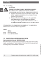
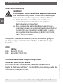
3.8 Ex marking
DANGER!
Danger to life due to loss of explosion protection
Non-observance of these instructions and their
contents may result in the loss of explosion protection.
▶
Observe the safety instructions in this chapter and
further explosion protection instructions in these
operating instructions.
▶
Observe the information given in the applicable
type examination certificate and the relevant
country-specific regulations for installation and use
in hazardous areas (e.g. IEC 60079-14, NEC, CEC).
Check whether the classification is suitable for the application.
Observe the relevant national regulations.
ATEX
IECEx
II 2G Ex ia IIC T6 Gb
II 2D Ex ia IIIB T85°C Db
3.9 Specifications and temperature limits
Ingress protection per IEC/EN 60529
For information on the ingress protection of the respective instru-
ment, see chapter 9 “Specifications”. For the IECEx assessment,
IP20 ingress protection was assumed.
3. Safety

13
11041781.04 01/2020 EN/DE
Pressure gauge with reed contact model 851-A, for Ex areas
EN
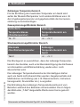
Permissible temperature range
For determining the maximum temperature at the instrument,
besides the medium temperature also other influences such as
the ambient temperature and, if applicable, the solar irradiation
must be taken into account.
Gas hazardous areas
Required temperature class
(ignition temperature)
Permissible temperature
range at the instrument
T6 ... T1 -20 ... +70 °C
Dust hazardous areas
Maximum surface
temperature
Permissible temperature
range at the instrument
T85°C -20 ... +70 °C
The installation should be made in such a way that the temper-
ature range of the instrument, also considering the effects of
convection and thermal radiation, neither exceeds nor falls below
the permissible limits.
The permissible temperature ranges of the contact models must
not be exceeded at the instrument either. If necessary, measures
for cooling (e.g. syphon, instrumentation valve, diaphragm seal
etc.) have to be taken.
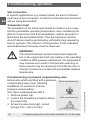
Compliance with the permissible temperature range during
operation must be ensured by the operator. The area shown in the
following picture under “T-Ref” can be used for this purpose.
3. Safety

14
11041781.04 01/2020 EN/DE
Pressure gauge with reed contact model 851-A, for Ex areas
EN
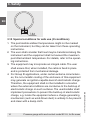
3.10 Special conditions for safe use (X conditions)
1. The permissible ambient temperatures might not be marked
on the instrument, but they can be taken from these operating
instructions.
2. The user shall consider that heat may be transferred along the
instrument and the equipment shall not exceed the maximum
permitted ambient temperature. For details, refer to the operat-
ing instructions.
3. The equipment may incorporate an integral cable. The user
shall ensure that, when installed, the cable is fixed in place
and is protected from mechanical damage.
4. For Group III applications, under certain extreme circumstanc-
es, the non-metallic coating of the enclosure of this equipment
may generate an ignition-capable level of electrostatic charge.
Therefore, the equipment shall not be installed in a location
where the external conditions are conducive to the build-up of
electrostatic charge on such surfaces. The user/installer shall
implement precautions to prevent the build-up of electrostatic
charge, e.g. locate the equipment where a charge-generating
mechanism (such as wind-blown dust) is unlikely to be present
and clean with a damp cloth.
3. Safety
T-Ref

15
11041781.04 01/2020 EN/DE
Pressure gauge with reed contact model 851-A, for Ex areas
EN
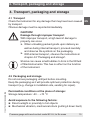
4. Transport, packaging and storage
4.1 Transport
Check the instrument for any damage that may have been caused
by transport.
Obvious damage must be reported immediately.
CAUTION!
Damage through improper transport
With improper transport, a high level of damage to
property can occur.
▶
When unloading packed goods upon delivery as
well as during internal transport, proceed carefully
and observe the symbols on the packaging.
▶
With internal transport, observe the instructions in
chapter 4.2 “Packaging and storage”.
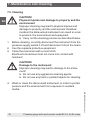
Shocks can cause small bubbles to form in the fill fluid
of filled instruments. This has no effect on the function
of the instrument.
4.2 Packaging and storage
Do not remove packaging until just before mounting.
Keep the packaging as it will provide optimum protection during
transport (e.g. change in installation site, sending for repair).
Permissible conditions at the place of storage:
Storage temperature: -20 ... +70 °C
Avoid exposure to the following factors:
■
Direct sunlight or proximity to hot objects
■
Mechanical vibration, mechanical shock (putting it down hard)
4. Transport, packaging and storage

16
11041781.04 01/2020 EN/DE
Pressure gauge with reed contact model 851-A, for Ex areas
EN
■
Soot, vapour, dust and corrosive gases
■
Hazardous environments, flammable atmospheres
Store the instrument in its original packaging in a location that
fulfils the conditions listed above.
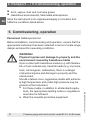
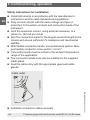
5. Commissioning, operation
Personnel: Skilled personnel
Before installation, commissioning and operation, ensure that the
appropriate instrument has been selected in terms of scale range,
design and specific measuring conditions.
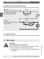
WARNING!
Physical injuries and damage to property and the
environment caused by hazardous media
Upon contact with hazardous media (e.g. with flamma-
ble or toxic substances), harmful media (e.g. corrosive,
toxic, carcinogenic, radioactive), there is a danger
of physical injuries and damage to property and the
environment.
Should a failure occur, aggressive media with extreme-
ly high temperature and under high pressure may be
present at the instrument.
▶
For these media, in addition to all standard regula-
tions, the appropriate existing codes or regulations
must also be followed.
▶
Wear the requisite protective equipment.
4. Transport ... / 5. Commissioning, operation

17
11041781.04 01/2020 EN/DE
Pressure gauge with reed contact model 851-A, for Ex areas
EN
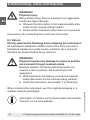
WARNING!
Physical injuries and damage to property and the
environment caused by media escaping under
high pressure
With the pressurisation of the instrument, as a result of
poor sealing of the process connection, media under
high pressure can escape.
Due to the high energy of the media that can escape in
the event of a failure, the possibility of physical injuries
and damage to property exists.
▶
The sealing of the process connection must be
carried out expertly and checked for leak tightness.
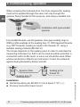
5.1 Mechanical connection
In accordance with the general technical regulations for pressure
gauges (e.g. EN 837-2 “Selection and installation recommenda-
tions for pressure gauges”).
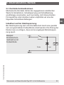
Instruments must be grounded via the process connection. This is
why electrically conductive sealing should be used at the process
connection. Alternatively, take other measures for grounding.
Measures for grounding applied ex works (e.g. welding spots or
fuse plates) must therefore be used to integrate the instruments
into the equipotential bonding system and must not be removed
under any circumstances. Ensure that the measures for grounding
are reinstalled after dismounting (e.g. replacing the instrument).
5. Commissioning, operation

18
11041781.04 01/2020 EN/DE
Pressure gauge with reed contact model 851-A, for Ex areas
EN
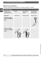
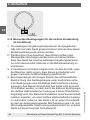
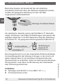
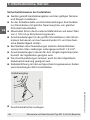
When screwing the instruments in, the force required for sealing
must not be applied through the case, but only through the
spanner flats provided for this purpose, and using a suitable tool.
For parallel threads, use flat gaskets, lens-type sealing rings or
WIKA profile sealings at the sealing face . With tapered threads
(e.g. NPT threads), sealing is made in the threads , using a
suitable sealing material (EN 837-2).
The torque depends on the sealing used. In order to orientate the
measuring instrument so that it can be read as well as possible, a
connection with LH-RH union or union nut should be used. When
a blow-out device is fitted to an instrument, it must be protected
against being blocked by debris and dirt.
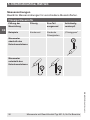
Installation
■
Nominal position per EN 837-3 / 9.6.6 figure 7: 90° ( ⊥ )
■
Process connection lower mount
Installation with open-ended
spanner
Sealing in the
thread
Spanner flats
Sealing face
5. Commissioning, operation

19
11041781.04 01/2020 EN/DE
Pressure gauge with reed contact model 851-A, for Ex areas
EN
■
With filled versions the vent valve at the top of the case must
be opened before commissioning!
■
For outdoor applications, the selected installation location has
to be suitable for the specified ingress protection, so that the
instrument is not exposed to impermissible weather conditions.
■
In order to avoid any additional heating, the instruments must
not be exposed to direct solar irradiation while in operation!
■
To ensure that the pressure can be safely vented in the case of
failure, instruments with blow-out device or blow-out back must
keep a minimum distance of 20 mm from each object.
Requirements for the installation point
If the line to the measuring instrument is not adequately stable, an
instrument mounting bracket should be used for fastening. If vibra-
tions cannot be avoided by means of suitable installation, filled
instruments should be used. The instruments should be protected
against coarse dirt and wide fluctuations in ambient temperature.
Permissible vibration load at the installation site
The instruments should always be installed in locations free from
vibration. If necessary, it is possible to isolate the instrument from
the mounting point, e.g. by installing a flexible connection line
between the measuring point and the instrument and mounting
the instrument on a suitable bracket.
If this is not possible, the following limit values must not be
exceeded:
Frequency range < 150 Hz
Acceleration < 0.5 g (5 m/s
2
)
5. Commissioning, operation

20
11041781.04 01/2020 EN/DE
Pressure gauge with reed contact model 851-A, for Ex areas
EN
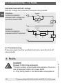
Test connection
In specific applications (e.g. steam boilers) the shut-off devices
must have a test connection, so that the instrument can be tested
without being dismounted.
Temperature load
The installation of the instrument should be made in such a way
that the permissible operating temperature, also considering the
effects of convection and thermal radiation, neither exceeds nor
falls below the permissible limits. Thus the instrument and the
shut-off device must be protected by sufficiently long measuring
lines or syphons. The influence of temperature on the indication
and measurement accuracy must be observed.
WARNING!
The actual maximum surface temperature depends
not on the equipment itself, but mainly on the operating
conditions. With gaseous substances, the temperature
may increase as a result of compression warming. In
these cases it may be necessary to throttle the rate of
change of pressure or reduce the permissible medium
temperature.
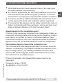
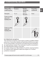
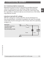
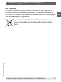
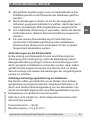
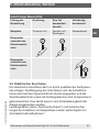
Commissioning of pressure compensating valve
Instruments which are fitted with a pressure
compensating valve must, following
installation, be vented for internal
pressure compensation.
Tool: Open-ended spanner SW 9
1. Remove plastic cap
2. Loosen the threaded connection above
the valve body
3. Screw the valve body tight, turned
through 180°, with ≤ 4.5 Nm
After commissioning
Before commissioning
5. Commissioning, operation
Seite wird geladen ...
Seite wird geladen ...
Seite wird geladen ...
Seite wird geladen ...
Seite wird geladen ...
Seite wird geladen ...
Seite wird geladen ...
Seite wird geladen ...
Seite wird geladen ...
Seite wird geladen ...
Seite wird geladen ...
Seite wird geladen ...
Seite wird geladen ...
Seite wird geladen ...
Seite wird geladen ...
Seite wird geladen ...
Seite wird geladen ...
Seite wird geladen ...
Seite wird geladen ...
Seite wird geladen ...
Seite wird geladen ...
Seite wird geladen ...
Seite wird geladen ...
Seite wird geladen ...
Seite wird geladen ...
Seite wird geladen ...
Seite wird geladen ...
Seite wird geladen ...
Seite wird geladen ...
Seite wird geladen ...
Seite wird geladen ...
Seite wird geladen ...
Seite wird geladen ...
Seite wird geladen ...
Seite wird geladen ...
Seite wird geladen ...
Seite wird geladen ...
Seite wird geladen ...
Seite wird geladen ...
Seite wird geladen ...
Seite wird geladen ...
Seite wird geladen ...
Seite wird geladen ...
Seite wird geladen ...
Seite wird geladen ...
Seite wird geladen ...
Seite wird geladen ...
Seite wird geladen ...
Seite wird geladen ...
Seite wird geladen ...
Seite wird geladen ...
Seite wird geladen ...
-
 1
1
-
 2
2
-
 3
3
-
 4
4
-
 5
5
-
 6
6
-
 7
7
-
 8
8
-
 9
9
-
 10
10
-
 11
11
-
 12
12
-
 13
13
-
 14
14
-
 15
15
-
 16
16
-
 17
17
-
 18
18
-
 19
19
-
 20
20
-
 21
21
-
 22
22
-
 23
23
-
 24
24
-
 25
25
-
 26
26
-
 27
27
-
 28
28
-
 29
29
-
 30
30
-
 31
31
-
 32
32
-
 33
33
-
 34
34
-
 35
35
-
 36
36
-
 37
37
-
 38
38
-
 39
39
-
 40
40
-
 41
41
-
 42
42
-
 43
43
-
 44
44
-
 45
45
-
 46
46
-
 47
47
-
 48
48
-
 49
49
-
 50
50
-
 51
51
-
 52
52
-
 53
53
-
 54
54
-
 55
55
-
 56
56
-
 57
57
-
 58
58
-
 59
59
-
 60
60
-
 61
61
-
 62
62
-
 63
63
-
 64
64
-
 65
65
-
 66
66
-
 67
67
-
 68
68
-
 69
69
-
 70
70
-
 71
71
-
 72
72


in anderen Sprachen
Verwandte Artikel
-
WIKA PG23HP-P tag:model:PG23HP-S Bedienungsanleitung
-
-
-
-
-
-
-
-
-