CombiSteel 7455.0999 Benutzerhandbuch
- Kategorie
- Friteusen
- Typ
- Benutzerhandbuch

Fryer
7455.0976 - 7455.0999
User Manual
Gebruikershandleiding
Gebrauchsanweisung
Le mode d’emploi

2
www.combisteel.com
CONTENT
ENGLISH
1. WARNINGS .................................................................................................................................................................. 4
2. INTRODUCTION ........................................................................................................................................................... 5
2.1 GENERAL ............................................................................................................................................................... 5
2.2 WARRANTY ............................................................................................................................................................ 5
3. GENERAL INFORMATION ............................................................................................................................................. 5
3.1 INSPECTION ........................................................................................................................................................... 5
3.2 OPERATOR MANUAL .............................................................................................................................................. 6
3.3 INSTALLATION ........................................................................................................................................................ 6
3.4 GAS CONNECTION ................................................................................................................................................. 6
3.5 GAS PRESSURE ....................................................................................................................................................... 6
3.6 COMMISSIONING .................................................................................................................................................. 6
4. SPECIFICATIONS ........................................................................................................................................................... 6
4.1 INSTALLATION ........................................................................................................................................................ 6
4.2 APPLIANCE SPECIFICATION .................................................................................................................................... 7
4.3 TEST POINT PRESSURE ........................................................................................................................................... 8
4.4 VENTILATION AND AIR SUPPLY .............................................................................................................................. 8
4.5 DIMENSIONS ......................................................................................................................................................... 8
4.6 ACCESSORIES ......................................................................................................................................................... 8
5. OPERATING INSTRUCTIONS ......................................................................................................................................... 9
5.1 LIGHTING INSTRUCTIONS ...................................................................................................................................... 9
5.2 IGNITION PROCEDURE........................................................................................................................................... 9
6. OPERATOR MAINTENANCE ........................................................................................................................................ 11
6.1 CLEANING STAINLESS STEEL ................................................................................................................................ 11
7. SERVICE ..................................................................................................................................................................... 12
7.1 RECOMMENDED SERVICE .................................................................................................................................... 12
7.2 BURNER ADJUSTMENTS ...................................................................................................................................... 12
7.3 SPARE PARTS ........................................................................................................................................................ 13
8. TROUBLE SHOOTING ................................................................................................................................................. 13
NEDERLANDS
1. WAARSCHUWINGEN .................................................................................................................................................. 14
2. INTRODUCTIE ........................................................................................................................................................ 15
3. ALGEMENE INFORMATIE ........................................................................................................................................... 15
3.1 INSPECTIE ............................................................................................................................................................ 15
3.2 HANDLEIDING GEBRUIKER .................................................................................................................................. 16
3.3 INSTALLATIE ......................................................................................................................................................... 16
3.4 GASAANSLUITING ................................................................................................................................................ 16
3.5 GASDRUK ............................................................................................................................................................. 16
3.6 INBEDRIJFSTELLING ............................................................................................................................................. 16
4. SPECIFICATIES ............................................................................................................................................................ 16
4.1 INSTALLATIE ......................................................................................................................................................... 16
4.2 AANSLUITSPECIFICATIE ........................................................................................................................................ 17
4.3 DRUKTESTPUNT ................................................................................................................................................... 18
4.4 VENTILATIE EN LUCHTTOEVOER .......................................................................................................................... 18
4.5 AFMETINGEN ....................................................................................................................................................... 18
4.6 ACCESSOIRES ....................................................................................................................................................... 18
5. GEBRUIKSAANWIJZING .............................................................................................................................................. 19
5.1 ONTSTEKINGSINSTRUCTIES ................................................................................................................................. 19
5.2 ONTSTEKINGSPROCEDURE .................................................................................................................................. 19
6. GEBRUIKERSONDERHOUD ......................................................................................................................................... 21
7. SERVICE ..................................................................................................................................................................... 22
7.1 AANBEVOLEN SERVICE ........................................................................................................................................ 22
7.2 BRANDER BIJSTELLEN .......................................................................................................................................... 22
7.3 RESERVEONDERDELEN ........................................................................................................................................ 23
8. PROBLEMEN OPLOSSEN ............................................................................................................................................ 23

3
www.combisteel.com
DEUTSCH
1. WARNHINWEISE ........................................................................................................................................................ 24
2. EINLEITUNG ............................................................................................................................................................... 25
2.1 ALLGEMEINES ...................................................................................................................................................... 25
2.2 GEWÄHRLEISTUNG .............................................................................................................................................. 25
3. ALLGEMEINE INFORMATIONEN ................................................................................................................................. 26
3.1 ÜBERPRÜFUNG.................................................................................................................................................... 26
3.2 BEDIENUNGSANLEITUNG .................................................................................................................................... 26
3.3 INSTALLATION ...................................................................................................................................................... 26
3.4 GASANSCHLUSS ................................................................................................................................................... 26
3.5 GASDRUCK ........................................................................................................................................................... 26
3.6 INBETRIEBNAHME ............................................................................................................................................... 26
4. SPEZIFIKATIONEN ....................................................................................................................................................... 27
4.1 INSTALLATION ...................................................................................................................................................... 27
4.2 GERÄTESPEZIFIKATIONEN .................................................................................................................................... 28
4.3 TESTPUNKT DES GASDRUCKS .............................................................................................................................. 29
4.4 BELÜFTUNG UND LUFTZUFUHR .......................................................................................................................... 29
4.5 ABMESSUNGEN ................................................................................................................................................... 29
4.6 ZUBEHÖR ............................................................................................................................................................. 29
5. BETRIEBSANLEITUNG ................................................................................................................................................. 29
5.1 BEFEUERUNGSINSTRUKTIONEN .......................................................................................................................... 29
5.2 ZÜNDUNGSVORGANG ......................................................................................................................................... 30
6. WARTUNGSARBEITEN DURCH DEN BENUTZER ......................................................................................................... 32
6.1 REINIGUNG VON EDELSTAHL ............................................................................................................................... 32
7. WARTUNG ................................................................................................................................................................. 32
7.1 EMPFOHLENE SERVICEARBEITEN ........................................................................................................................ 33
7.2 BRENNEREINSTELLUNGEN ................................................................................................................................... 33
7.3 ERSATZTEILE ........................................................................................................................................................ 33
8. FEHLERSUCHE UND -BEHEBUNG ............................................................................................................................... 34
FRANÇAIS
1. AVERTISSEMENTS ...................................................................................................................................................... 35
2. INTRODUCTION ..................................................................................................................................................... 36
3. INFORMATION GENERALE ......................................................................................................................................... 36
3.1 INSPECTION ......................................................................................................................................................... 36
3.2 MANUEL DE L’UTILISATEUR ................................................................................................................................. 37
3.3 INSTALLATION ...................................................................................................................................................... 37
3.4 RACCORDEMENT AU GAZ .................................................................................................................................... 37
3.5 PRESSION DU GAZ ............................................................................................................................................... 37
3.6 MISE EN SERVICE ................................................................................................................................................. 37
4. SPECIFICATIONS ......................................................................................................................................................... 37
4.1 INSTALLATION ...................................................................................................................................................... 37
4.2 SPÉCIFICATION DE RACCORDEMENT ................................................................................................................... 38
4.3 POINT DE TEST DE PRESSION ............................................................................................................................... 39
4.4 VENTILATION ET AERATION ................................................................................................................................. 39
4.5 DIMENSIONS ....................................................................................................................................................... 39
4.6 ACCESSOIRES ....................................................................................................................................................... 39
5. MODE D’EMPLOI ....................................................................................................................................................... 40
5.1 INSTRUCTIONS D’ALLUMAGE .............................................................................................................................. 40
5.2 PROCEDURE D’ALLUMAGE ................................................................................................................................... 40
6. ENTRETIEN D’UTILISATION ........................................................................................................................................ 42
7. SERVICE ..................................................................................................................................................................... 43
7.1 SERVICE RECOMMANDE ...................................................................................................................................... 43
7.2 REGLAGES DE BRULEUR....................................................................................................................................... 43
7.3 PIECES DE RECHANGE .......................................................................................................................................... 44
8. RESOLUTION DE PROBLEMES .................................................................................................................................... 44

4
www.combisteel.com
1. WARNINGS
IMPROPER INSTALLATION, ADJUSTMENT, ALTERATION, SERVICE OR
MAINTENANCE CAN CAUSE INJURY OR DEATH. THE INSTRUCTION MANUAL
MUST BE READ CAREFULLY BEFORE INSTALLING, OPERATING OR SERVICING
THIS EQUIPMENT
TO BE INSTALLED ONLY BY AN AUTHORISED PERSON IN ACCORDANCE WITH
LOCAL AUTHORITY, GAS, ELECTRICITY, AND ANY APPLICABLE STATUTORY
REGULATIONS AND MANUFACTURER REQUIREMENTS.
THIS EQUIPMENT IS DESIGNED FOR COMMERCIAL CATERING PURPOSES AND
WILL GENERATE SIGNIFICANT HEAT. IT CAN ONLY BE USED BY A QUALIFIED
PEOPLE. HOT SURFACES WILL CAUSE BURNS. A HAZARD AND RISK
ASSESSMENT MUST BE UNDERTAKEN BY OWNERS AND ALL OPERATORS
MUST BE AWARE OF THESE.
DO NOT STORE OR USE FLAMMABLE LIQUIDS NEAR THIS APPLIANCE. THE
PARTS WHICH HAVE BEEN PROTECTED BY THE MANUFACTURER OR HIS AGENT
SHALL NOT BE ADJUSTED BY THE USER.
DO NOT SPRAY AEROSOLS NEAR THIS APPLIANCE WHILE IT IS IN OPERATION.
INSTALLATION CLEARANCES AS SPECIFIED MUST BE OBSERVED.

5
www.combisteel.com
IF YOU SMELL GAS, TURN THE UNIT AND THE MAIN GAS SUPPLY VALVE TO THE
UNIT OFF. CONTACT YOUR GAS SUPPLIER OR AN AUTHORISED PERSON.
BEFORE TURNING ON THE MAIN GAS SUPPLY, CHECK THE UNIT TO BE CERTAIN
THAT ALL THE VALVES ARE IN THE “OFF” POSITION.
PLEASE KEEP THIS MANUAL FOR FUTURE REFERENCE AND REFERENCE BY ALL OPERATORS.
2. INTRODUCTION
2.1 GENERAL
The gas fuelled fryer is designed for commercial catering purposes and incorporates a wide range of features to
benefit the customer.
2.2 WARRANTY
This product’s warranty is subject to the terms of a local distributor in your own country and is subject to the
correct installation, operation, maintenance and care of the equipment.
Warranty does not extend to:
• Damages caused during shipping
• Damage as a result of incorrect installation.
• Damage as a result of incorrect operation
• Damages caused by unauthorised service and use of non-original parts
• Gas supply issues to the equipment
• Failure resulting from improper maintenance.
• Failure as a result of tampering with, removal of, or changing any pre-set control or safety device
For all warranty work, authorized service and genuine and authorized spare parts, please contact your local
dealer
Please ensure you quote the Model and Serial Number of the unit. The Model and Serial Number of the unit
are on the data plate. Please provide this information for after sales service.
3. GENERAL INFORMATION
3.1 INSPECTION
Please inspect the unit on receipt. If the unit is damaged, contact the carrier immediately and file a damage claim
with them. Save all packing materials when filing a claim. Freight damage claims are the responsibility of the
purchaser and are not covered under warranty.

6
www.combisteel.com
3.2 OPERATOR MANUAL
This manual contains important information for your safety and the installation, operation, maintenance and
service of this equipment. Please read the manual carefully and ensure all operators of the equipment are aware
of the contents and safety requirements.
Warning: You must assess all hazards and risks associated with the operation of the equipment in your
environment and advise all operators of them.
3.3 INSTALLATION
This equipment must be installed by an authorized person in accordance with local authority, gas, electricity, and
any applicable statutory regulations and manufacturer requirements.
3.4 GAS CONNECTION
The appliance must be connected by an authorized person to the gas type specified on the unit. The gas type is
shown adjacent to the gas connection point on the rear panel and on the data plate. Connect to and use only
the correct type of gas.
3.5 GAS PRESSURE
The authorized person installing this equipment must ensure that the gas operating pressure is the same as
shown on the data plate and that there is sufficient gas volume.
3.6 COMMISSIONING
The authorized person installing this equipment must commission the equipment in accordance with local gas
safety regulations - gas leakage, operational checking, adjustments and instructing the owner on use of the
equipment are prescribed requirements.
4. SPECIFICATIONS
4.1 INSTALLATION
THIS EQUIPMENT MUST BE INSTALLED BY AN AUTHORIZED PERSON IN ACCORDANCE
WITH LOCAL AUTHORITY, GAS, ELECTRICITY, ANY APPLICABLE STATUTORY
REGULATIONS AND MANUFACTURER REQUIREMENTS.
NOTE: INSTALLATION IS THE RESPONSIBILITY OF THE OWNER
Gas Inlet Connection: 1/2” BSP Female.
Gas Connection Point: The gas connection point is located at the rear of the unit.
Details are shown in the drawings at the rear of this manual.
Gas Connection: The appliance must be connected by an authorized person to the gas type specified
on the unit. The gas type is shown adjacent to the gas connection point on the rear
panel and on the data plate. Connect to and use only the correct type of gas.
The authorized person installing this equipment must comply with local gas safety standard. Prescribed
requirements include, commission the equipment, gas leakage testing, operational checking and adjustments.
All units are tested and adjusted at the factory; however, all burners and pilots must be checked at the installed
location and adjusted as necessary.

7
www.combisteel.com
Data Plate: The data plate is located at the rear of the fryer
Installation Clearances: The MINIMUM clearance from combustible surfaces is;
Sides 150 mm, and
Rear 50mm
Adequate clearance must also be provided for service.
Levelling: To adjust the legs to level the unit to the floor and/or to slightly adjust the height of
the unit, raise the front of the unit and adjust the legs (ensure safe work practices).
Similarly, raise the back of the unit and adjust the legs. DO NOT LAY THE UNIT ON ITS
BACK. ENSURE THE UNIT IS LEVEL.
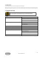
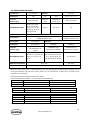
4.2 APPLIANCE SPECIFICATION
Product name Gas Fryer Type of appliances Type A1
Gas Category I2H I2E I2E+ I2(43.46 -45.3 MJ / m3 (0 ° C))
Gas and Supply Pressure G20 at 20 mbar G20 at 20
mbar
G20/G25 at
20/25 mbar G25.3 at 25 mbar
Country of Destination
AT, BG, CR, CZ, DK,
EE, FI, GR, HR, HU,
IS, IE, IT, LV, LT, NO,
PT, RO, SK, SI, ES, SE,
CH, TR and GB
BE, FR DE, LU, PL NL
Injector Size Ø 2.30 mm Ø 2.24 mm
Gas Consumption
34kW(3.6m3/h) for GF4 ;
27KW(2.9m3/h) for GF3
32kW(3.4m3/h) for GF4
24kW(2.5m3/h) for GF3
Product name Gas Fryer Type of appliances
Appliance category I3+(28-30/37) I3B/P(30) I3B/P(50)
Gas and Supply Pressure
G30 Butane at 28-30 mbar
and G31Propane at
37mbar
G30 Butane and
G31Propane at 30mbar
G30 Butane and
G31Propane at 50mbar
Country of Destination
BE,CH,CY,CZ,ES,FR,
GB,GR,IE,IT,LT,LU,LV,PT,SK
,SI
BE,CY,DK,EE,FI,FR,HU,IT,LT
,NL,NO,SE,
SI,SK,RO,HR,TR,BG,
IS,LU,MT
AT,CH,DE,SK
Injector Size Ø 1.5 mm Ø 1.3 mm
Gas Consumption 34kW (2681g/h) for GF4L; 27kW (2129g/h) for GF3L
Warning: This appliance shall be installed in conformity with the current regulations and used only in a well-
ventilated location. Consult the instructions before installing and using this appliance.

8
www.combisteel.com
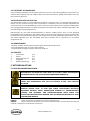
Burner rating of ignition pilot: 750W
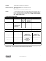
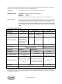
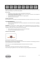
Nominal Gas Consumption Table for I2H only (reference only)
BURNER
Test pressure at gas inlet
Test pressure at test point
GF4
20 mbar
13.5 mbar
GF3
20 mbar
14.7 mbar
BURNER
Test pressure at gas inlet
Test pressure at test point
GF4 / GF3
25 mbar
20 mbar
BURNER
Test pressure at gas inlet
Test pressure at test point
GF4L
29 mbar
28.0mbar
GF3L
29mbar
28.4mbar
GF4L
50 mbar
48.5mbar
GF3L
50mbar
49.5mbar
Note: The pressure test point is located on the gas manifold (refer below).
4.3 TEST POINT PRESSURE
The pressure test point is located on the gas manifold and is accessed by opening the door. The test point
pressure is shown in the ‘Nominal Gas Consumption Table’ above and is set with the burners operating at
maximum setting.
4.4 VENTILATION AND AIR SUPPLY
All gas burners and pilots require sufficient air to operate. For optimum performance and for your safety, it is
ESSENTIAL that the equipment, in the installed position, has the proper air and ventilation and the correct
exhaust/canopy and air balance. The correct installation and compliance with all regulatory and other
requirements is the responsibility of the purchaser/owner.
Please note that a strong exhaust canopy will create a vacuum if there is insufficient replacement air. The amount
of air exhausted must be replaced by an equal amount of air. Airflow to the appliance must not be blocked or
restricted (e.g. large objects should not be placed in front of the appliance). The flue must never be covered or
restricted in any way.
4.5 DIMENSIONS
* Please note that the outside dimensions of GF3/GF4 and GF3L/GF4L are identical.
* Product dimensions are 393 x 750x 1160 mm
* Packing dimensions are 510 x 820 x 1230 mm
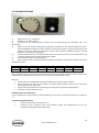
4.6 ACCESSORIES
1. Fry baskets @ 2
2. Rack @ 1
3. Oil extension pipe @ 1
4. Clog clearance prod @ 1
5. Operating manual @ 1

9
www.combisteel.com
5. OPERATING INSTRUCTIONS
5.1 LIGHTING INSTRUCTIONS
DO NOT OPERATE THE UNIT UNLESS IT HAS BEEN INSTALLED AND COMMISSIONED
BY AN AUTHORIZED PERSON.
BEFORE TURNING ON THE MAIN GAS SUPPLY, CHECK AND ENSURE THAT ALL THE
VALVES ARE IN THE “OFF” POSITION.
THIS EQUIPMENT IS DESIGNED FOR COMMERCIAL CATERING PURPOSES AND WILL
GENERATE SIGNIFICANT HEAT. HOT SURFACES WILL CAUSE BURNS. A HAZARD AND
RISK ASSESSMENT MUST BE UNDERTAKEN BY OWNERS AND ALL OPERATORS MADE
AWARE OF THESE.
NOTE: Ensure the gas supply to the equipment is turned ON.
NOTE: For your safety, the valve comes with a flame failure sensing device. If the device does not sense a flame,
gas supply to the burner will be cut.
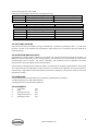
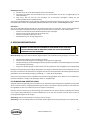
5.2 IGNITION PROCEDURE
NOTE: Ensure the gas supply to the equipment is turned ON
1) Starting from the “0” position
2) Press the PILOT ★ position.
3) Manually light the pilot by use of a spark gun or lighter.
4) Continually press the ★ button for 15 seconds. Now when the ★ button is released, the pilot flame
should stay alight. If it does not, go back to step (1) and start all over again. When the automatic valve
senses that the pilot is alight, the gas flow to the main burner is opened.
5) If the pilot flame cannot be lit after repeated attempts, check out the troubleshooting page of this
manual.
6) Turn the knob to setting “1”.
7) Turn the knob to the setting of your desired temperature. Please refer to the following table.

10
www.combisteel.com
Setting
1
2
3
4
5
6
7
oC
120
135
145
160
175
185
195
oF
248
275
293
320
347
365
383
When the oil temperature reaches the desired temperature (normally at this point of time, the main burner will
be temporarily closed), the fryer can be loaded.
Warning:
• Operator must follow the procedure in operating this fryer
• Take particular care when loading the food into the fryer to avoid being scalded by splashing oil.
• Hang the fry basket on the hangar until oil is dripped out.
• Do not overload the fryer basket.
Pilot Standby Position
To turn the main burner off and keep the pilot ON, rotate the knob to “0” position.
Shut Down/Pilot OFF
• Turn the control knob to “0” position
• Depress the ● knob. Gas supply to both the main burner as well as the pilot burner will be cut off
simultaneously.
NOTE: If the pilot flame were accidentally extinguished, the flame failure safety device would operate and cut
the gas flow to the main burner. It would then be necessary to re light the pilot by following the above procedure.
• Wait for about 15 seconds for the valve to reset.
• Repeat from step (1) of the IGNITION PROCEDURE
Thermal cut out tripping:
Wait for about 10 minutes for the oil to cool down
Press the button on the thermal cut out. If the thermal cut out cannot be manually reset, call your service agent.
Repeat step (1) from IGNITION PROCEDURE to light up the fryer again.
Adding Oil
Caution: Add oil to fry pot between the maximum and minimum level.
Caution: Do not use solid oil or solid shortening. Only liquid oil should be used in this fryer
Oil filtering procedure:
1) Turn off the fryer and let it cool down for about 20 minutes
2) Screw in the Oil drain extension pipe (hung on the inside of the door) to the drain valve outlet
3) Make sure that the nozzle end of the oil drain extension pipe faces an oil collector (or an oil filtering cart)
Pull the safety latch of the lever and start turning the lever anticlockwise slowly.
CAUTION: DO NOT TURN THE LEVER TOO FAST. THIS COULD RESULT IN HOT OIL SPLASHING OUT FROM THE
DRAIN NOZZLE

11
www.combisteel.com
Oil filtering
Oil should be filtered regularly in order to lengthen its usable life span. This will also reduce the operating cost.
The following factors all contribute to the shortening of oil life.
← Contact with air
← Carbonated food crumbs and particles.
← Contact with any surface other than stainless steel.
← Contact with seasoning, spices and salt.
Cooking food under a temperature too high
6. OPERATOR MAINTENANCE
USE ONLY SUITABLE CHEMICALS AND OBSERVE ALL MANUFACTURER SAFETY
REQUIREMENTS FOR SAFE HANDLING AND USE.
Warning: Ensure the appliance is off and the parts are cool to touch.
1. Avoid splashing water onto any parts and piping.
2. Check the piping connections and gas circuitry regularly.
3. Avoid clogging of the flue gas ventilation. Any obstacles in the flue can cause incomplete combustion.
4. Make sure the gas type and pressure conforms to the specification as shown in the data plate
Cleaning must be regular and thorough to ensure safe and efficient operation of the equipment and to prevent
flare-up. The amount of usage and the type of products being cooked will largely determine how often complete
cleaning is necessary - you must assess this.
To clean the items, use a suitable detergent and warm water and scrubbing brush. Repeated scrubbing will be
necessary if deposits are heavy and baked on.
6.1 CLEANING STAINLESS STEEL
Regularly wipe the surface with hot water and detergent. Rinse the washed area with a wet sponge and clean
water and wipe the area dry to prevent streaking. Follow this process and wash a small area at a time to prevent
chemical residue and streaking.
Stainless steel may discolour if overheated. These stains can usually be removed using an appropriate
powder/paste. To scrape off heavy deposits of grease and oil, use only wood or plastic tools as necessary.
Note: Never use steel wool to clean stainless steel.
Note: Damage may occur if chemicals not suitable for stainless steel are used.

12
www.combisteel.com
7. SERVICE
FOR YOUR SAFETY, ALL SERVICE WORK MUST BE CARRIED OUT BY AN AUTHORISED
PERSON AND USE ONLY ORIGINAL SUPPLIED AND SPECIFIED PARTS.
TEST ALL FITTINGS, PIPES AND PIPE CONNECTIONS FOR LEAKS IN ACCORDANCE
WITH APPROVED GAS LEAK TEST PROCESSES AND METHODS. DO NOT USE A FLAME.
7.1 RECOMMENDED SERVICE
It is recommended that your appliance be serviced by an authorized person every 12 months. This period is for
guidance purpose only and may vary based on usage of the equipment and operator care. Prescribed service
tasks include;
• Functional test of all components and clean and adjust as necessary.
• Inspect and clean all gas valves and lubricate with an industry approved lubricant.
• Inspect all gas piping.
• Check and adjust specified gas pressures.
• Leak test.
• Full operational, performance and safety test.
7.2 BURNER ADJUSTMENTS
Leak Test
1) Ensure that all control valves are in the OFF position.
2) Turn on the main gas supply valve.
3) Light all pilots.
4) Leak test all valves and fittings using approved methods.
5) Correct any leaks as required and re-check.
6) Shut off all valves and set the control knobs to “OFF” position.
Test Point Pressure
The pressure test point is located on the gas manifold. The gas manifold and pressure test point is accessed by
opening the fryer door. The test point pressure is shown in the ‘Nominal Gas Consumption Table’ and is set with
the burners operating at maximum setting.
Pilot Burner Adjustment
Set all pilots so that the flame envelops the tip of the thermocouple by adjusting the pilot flame adjusting screw
on the gas valve - clockwise to decrease, or counter clockwise to increase.
Service adjustment should not be necessary unless you’re changing the gas valve or performing a gas conversion.
Burner Adjustment
The burner orifices are fixed as specified and cannot be adjusted. The specified gas rate will be achieved if the
gas supply pressure and test point pressure is correct.
A distinct blue flame over the entire port area of the burner will be achieved at full rate when the air supply is
correct and the injector and burner are properly aligned.
If the flame is yellow and wavy, the cause needs to be established.
WARNING: If you are not competent in performing any service task or require assistance, please contact your
local service agent.

13
www.combisteel.com
7.3 SPARE PARTS
The spare parts used in the fryer are available at your local dealer.
Warning: Use only genuine spare parts. Use of non-authorized parts voids warranty and equipment approval.
8. TROUBLE SHOOTING
ALL SERVICE WORK TO BE COMPLETED BY AN AUTHORISED PERSON.
BURNERS
Condition
check
Pilot will not light.
Gas supply is on and gas pressure is correct
Blocked pilots
Pilot adjusting screw
Pilot repeatedly goes out.
Pilot flame size and position
Thermocouple
Flame safety device
Yellow Burner Flame.
Primary air
Flame lifting off burner ports.
Primary air
‘Popping’ after turning off.
Primary air
Burner flame too large.
Gas pressure
Delayed ignition.
Pilot flame
Burner and ports clean
Gas pressure
Flame burns back to orifice
Primary air

14
www.combisteel.com
1. WAARSCHUWINGEN
ONJUISTE INSTALLATIE, AANPASSING, WIJZIGING, SERVICE OF ONDERHOUD
KAN LEIDEN TOT LETSEL OF DOOD. DE HANDLEIDING MOET ZORGVULDIG
WORDEN GELEZEN VOORAFGAAND AAN HET INSTALLEREN, BEHEREN OF
ONDERHOUD VAN DEZE APPARATUUR
MAG ALLEEN WORDEN GEÏNSTALLEERD DOOR EEN BEVOEGD PERSOON
OVEREENKOMSTIG DE VOORSCHRIFTEN VAN DE LOKALE AUTORITEITEN, ALLE
TOEPASSELIJKE WETTELIJKE VOORSCHRIFTEN T.A.V. GAS EN ELEKTRICITEIT, EN
DE VEREISTEN VAN DE FABRIKANT
DIT APPARAAT IS ONTWORPEN VOOR COMMERCIËLE CATERINGDOELEINDEN
EN ZAL AANZIENLIJKE WARMTE GENEREREN. HET APPARAAT MOET
WORDEN GEBRUIKT DOOR GEKWALIFICEERDE PERSONEN. HETE
OPPERVLAKKEN KUNNEN BRANDWONDEN VEROORZAKEN. DE EIGENAREN
MOETEN EEN GEVAREN- EN RISICO-ANALYSE UITVOEREN EN DEZE ONDER DE
AANDACHT VAN ALLE GEBRUIKERS BRENGEN.
BEWAAR OF GEBRUIK GEEN BRANDBARE VLOEISTOFFEN IN DE BUURT VAN DIT
APPARAAT. DE DELEN DIE DOOR DE FABRIKANT OF ZIJN GEMACHTIGDE ZIJN
BEVEILIGD MOGEN NIET WORDEN AANGEPAST DOOR DE GEBRUIKER.
SPUIT GEEN AËROSOLS IN DE BUURT VAN DIT APPARAAT WANNEER DIT IN
GEBRUIK IS.
DE AANGEGEVEN INSTALLATIETOLERANTIEWAARDEN MOETEN WORDEN
NAGELEEFD.

15
www.combisteel.com
SCHAKEL ALS U GAS RUIKT HET APPARAAT DE HOOFDGASTOEVOERKLEP OP
HET APPARAAT UIT. NEEM CONTACT OP MET UW GASLEVERANCIER OF EEN
BEVOEGD PERSOON.
CONTROLEER HET APPARAAT, VOORDAT U DE HOOFDGASTOEVOER AANZET,
OM ER ZEKER VAN TE ZIJN DAT DE KLEPPEN IN DE "OFF" (”UIT”)-STAND ZIJN.
HOUD DEZE HANDLEIDING BIJ DE HAND VOOR CONSULTATIE IN DE TOEKOMST
EN TER REFERENTIE VOOR ALLE GEBRUIKERS.
2. INTRODUCTIE
2.1 ALGEMEEN
Deze gasgestookte friteuse is ontworpen voor commerciële cateringdoeleinden en omvat een breed scala van
functies ten bate van de klant.
2.2 GARANTIE
De garantie op dit product is onderworpen aan de voorwaarden van de plaatselijke distributeur in uw eigen land
en is afhankelijk van een juiste installatie, bediening, onderhoud en verzorging van de apparatuur.
De garantie geldt niet voor:
• Schade tijdens de verzending
• Schade als gevolg van onjuiste installatie.
• Schade als gevolg van onjuiste bediening
• Schade veroorzaakt door niet-bevoegde service en het gebruik van niet-originele onderdelen
• Problemen met de gastoevoer naar de apparatuur
• Storingen als gevolg van onjuist onderhoud.
• Storingen als gevolg van geknoei met, het verwijderen van, of het wijzigen van een vooraf ingestelde
controle- of veiligheidsvoorziening
Neem voor alle garantiewerkzaamheden, geautoriseerde service en originele en goedgekeurde reserve-
onderdelen, contact op met uw plaatselijke dealer
Zorg ervoor dat u het model- en serienummer van het apparaat vermeldt. Het model- en serienummer van
het apparaat zijn te vinden.
3. ALGEMENE INFORMATIE
3.1 INSPECTIE
Controleer het apparaat bij ontvangst. Als het apparaat beschadigd is, neem dan onmiddellijk contact op met de
vervoerder en dien een schadeclaim bij deze in. Bewaar al het verpakkingsmateriaal bij het indienen van een
claim. Vrachtschadeclaims zijn de verantwoordelijkheid van de koper en vallen niet onder de garantie.

16
www.combisteel.com
3.2 HANDLEIDING GEBRUIKER
Deze handleiding bevat belangrijke informatie voor uw veiligheid en de installatie, bediening, onderhoud en
service van deze apparatuur. Lees de handleiding zorgvuldig door en zorg ervoor dat alle gebruikers van de
apparatuur op de hoogte zijn van de inhoud en de veiligheidseisen.
Waarschuwing: U dient alle gevaren en risico's verbonden aan de werking van de apparatuur in uw omgeving te
beoordelen en alle gebruikers van uw bevindingen op de hoogte te stellen.
3.3 INSTALLATIE
Deze apparatuur moet worden geïnstalleerd door een bevoegd persoon in overeenstemming met alle
toepasselijke wettelijke voorschriften voor gas en elektriciteit van de plaatselijke overheid en de eisen van de
fabrikant.
3.4 GASAANSLUITING
Het apparaat moet worden aangesloten door een bevoegd persoon op het type gas aangegeven op het apparaat.
Het type gas staat vermeld naast het gasaansluitpunt op de achterzijde en op het typeplaatje. Alleen aansluiten
op en gebruiken met het juiste type gas.
3.5 GASDRUK
De bevoegde persoon die deze apparatuur installeert moet ervoor zorgen dat de gaswerkdruk overeenkomt met
die aangegeven op het typeplaatje en dat de beschikbare hoeveelheid gas voldoende is.
3.6 INBEDRIJFSTELLING
De bevoegd persoon die deze apparatuur installeert, moet de apparatuur in bedrijf stellen overeenkomstig de
plaatselijke bepalingen t.a.v. gasveiligheid - gaslekkage, operationele controle, aanpassingen, en het instrueren
van de eigenaar in het gebruik van de apparatuur zijn hierbij voorgeschreven eisen.
4. SPECIFICATIES
4.1 INSTALLATIE
DEZE APPARATUUR MOET WORDEN GEÏNSTALLEERD DOOR EEN BEVOEGD PERSOON
OVEREENKOMSTIG ALLE GELDENDE WETTELIJKE REGELINGEN T.A.V. GAS EN
ELEKTRICITEIT VAN DE PLAATSELIJKE OVERHEID EN DE EISEN VAN DE FABRIKANT.
OPMERKING: INSTALLATIE IS DE VERANTWOORDELIJKHEID VAN DE EIGENAAR
Gasinlaataansluiting: 1/2” BSP Female.
Gasaansluitpunt: Het gasaansluitpunt bevindt zich aan de achterzijde van het apparaat.
De details staan aangegeven in de tekeningen aan de achterzijde van deze handleiding.
Gasaansluiting: Het apparaat moet worden aangesloten door een bevoegd persoon op het type gas
aangegeven op het apparaat. Het type gas staat vermeld naast het gasaansluitpunt op
de achterzijde en op het typeplaatje. Alleen aansluiten op en gebruiken met het juiste
type gas.
De bevoegd persoon die deze apparatuur installeert moet de plaatselijke gasveiligheidsnormen naleven.
Voorgeschreven eisen hiervoor omvatten de inbedrijfstelling van de apparatuur, gaslekkage, operationele
controle en afstellingen.

17
www.combisteel.com
Alle apparaten zijn getest en afgesteld in de fabriek; alle branders en waakvlambranders moeten echter op de
locatie van de installatie worden gecontroleerd en zo nodig bijgesteld.
Typeplaatje: Het typeplaatje bevindt zich op de achterzijde van de friteuse.
Installatieafstanden: De MINIMUM afstand van brandbare oppervlakken is;
Zijkanten 150 mm, and
Achterzijde 50mm
Er dient ook voldoende ruimte te worden vrijgehouden voor serviceonderhoud.
Waterpas maken: Om de poten bij te stellen teneinde het apparaat waterpas met de vloer te krijgen
en/of om de hoogte van het apparaat ietsjes bij te stellen, til de voorkant van het
toestel wat op en stel de poten bij (zorg voor een veilige werkmethode). Til de
achterkant van het apparaat op soortgelijke manier wat op en stel de poten bij. LEG
HET APPARAAT NIET OP ZIJN RUG. ZORG ERVOOR DAT HET APPARAAT WATERPAS
STAAT.
4.2 AANSLUITSPECIFICATIE
Productnaam Gasfriteuse Type apparaat Type A1
Gas Categorie I2H I2E I2E+ I2(43.46 -45.3 MJ / m3 (0 ° C))
Gas en gastoevoerdruk G20 op 20 mbar G20 op 20
mbar
G20/G25 op
20/25 mbar G25.3 op 25 mbar
Land van bestemming
AT, BG, CR, CZ, DK,
EE, FI, GR, HR, HU,
IS, IE, IT, LV, LT, NO,
PT, RO, SK, SI, ES, SE,
CH, TR and GB
BE, FR DE, LU, PL NL
Injector Size Ø 2.30 mm Ø 2.24 mm
Gas Consumptie
34kW(3.6m3/h) voor GF4 ;
27KW(2.9m3/h) voor GF3
32kW(3.4m3/h) voor GF4
24kW(2.5m3/h) voor GF3
Productnaam Gasfriteuse Type apparaat
Gas Categorie I3+(28-30/37) I3B/P(30) I3B/P(50)
Gas en gastoevoerdruk
G30 Butane op 28-30
mbar en G31Propane op
37mbar
G30 Butane en
G31Propane op 30mbar
G30 Butane en
G31Propane op 50mbar
Land van bestemming
BE, CH, CY, CZ, ES, FR, GB,
GR, IE, IT, LT, LU, LV, PT,
SK, SI
BE, CY, DK, EE, FI, FR, HU,
IT, LT, NL, NO, SE, SI, SK,
RO, HR, TR, BG, IS, LU, MT
AT, CH, DE, SK
Injector Size Ø 1.5 mm Ø 1.3 mm
Gas Consumptie 34kW (2681g/h) voor GF4L; 27kW (2129g/h) voor GF3L
Waarschuwing: Dit apparaat moet in overeenstemming met de huidige regelgeving worden geïnstalleerd en mag
alleen gebruikt worden in een goed geventileerde locatie. Raadpleeg de instructies voorafgaand aan installatie
en gebruik van dit apparaat.

18
www.combisteel.com
Brandernotering van de waakvlambrander: 750W Nominal Gas Consumption Table (Nominaal gasverbruikstabel)
Nominal Gas Consumption Table voor I2H (enkel ter referentie)
Brander
Test druk gasinvoer
Test drukttestpunt
GF4
20 mbar
13.5 mbar
GF3
20 mbar
14.7 mbar
Brander
Test druk gasinvoer
Test drukttestpunt
GF4 / GF3
25 mbar
20 mbar
Brander
Test druk gasinvoer
Test drukttestpunt
GF4L
29 mbar
28.0mbar
GF3L
29mbar
28.4mbar
GF4L
50 mbar
48.5mbar
GF3L
50mbar
49.5mbar
Opmerking: Het druktestpunt bevindt zich op het gasspruitstuk (zie hieronder).
4.3 DRUKTESTPUNT
Het druktestpunt bevindt zich op het gasspruitstuk en is toegankelijk door het deurtje te openen. De druk bij het
druktestpunt staat aangegeven in de nominaal gasverbruikstabel hierboven en wordt ingesteld met de branders
op maximale instelling.
4.4 VENTILATIE EN LUCHTTOEVOER
Alle gasbranders en waakvlambranders hebben voldoende lucht nodig om naar behoren te functioneren. Voor
optimale prestaties en voor uw veiligheid is het ESSENTIEEL dat de apparatuur, in de geïnstalleerde positie, de
juiste luchttoevoer en ventilatie heeft en de juiste balans tussen uitlaat/kap en lucht. De juiste installatie en de
naleving van alle regelgeving en andere eisen is de verantwoordelijkheid van de koper/eigenaar.
Houd er rekening mee dat een sterke uitlaatkap een vacuüm zal creëren als er onvoldoende lucht ter vervanging
aanwezig is. De hoeveelheid uitgestoten lucht moet worden vervangen door een gelijke hoeveelheid lucht.
Luchtstroom naar de toestel moet niet worden geblokkeerd of beperkt (b.v. grote objecten moeten niet worden
geplaatst voor het toestel). De schoorsteen moet nooit bedekt of beperkt op geen enkele manier.
4.5 AFMETINGEN
* Merk op dat de buitenafmetingen van branders 3 en 4 identiek zijn.
* De productafmetingen zijn 393 x 750 x 1160 mm
* De afmetingen van de verpakking zijn 510 x 820 x 1230 mm
4.6 ACCESSOIRES
1. Friteusemanden @2
2. Rek @1
3. Olieverlengbuis @1
4. Priem voor het verwijderen van verstoppingen @1
5. Gebruikshandleiding @1

19
www.combisteel.com
5. GEBRUIKSAANWIJZING
5.1 ONTSTEKINGSINSTRUCTIES
STEL HET APPARAAT NIET IN WERKING TENZIJ HET IS GEÏNSTALLEERD EN IN BEDRIJF
GESTELD DOOR EEN DAARTOE BEVOEGD PERSOON.
CONTROLEER VOORDAT U DE HOOFDGASTOEVOER AANZET DAT ALLES IN ORDE IS
EN ZORG ERVOOR DAT ALLE KLEPPEN IN DE "OFF" (“UIT”)-STAND ZIJN.
DIT APPARAAT IS ONTWORPEN VOOR COMMERCIËLE CATERINGDOELEINDEN EN ZAL
AANZIENLIJKE WARMTE GENEREREN. HETE OPPERVLAKKEN KUNNEN
BRANDWONDEN VEROORZAKEN. DE EIGENAREN MOETEN EEN GEVAREN- EN
RISICO-ANALYSE UITVOEREN EN DEZE ONDER DE AANDACHT VAN ALLE GEBRUIKERS
BRENGEN.
OPMERKING: Zorg ervoor dat de gastoevoer naar de apparatuur ingeschakeld (“ON”) is.
OPMERKING: Voor uw eigen veiligheid is de klep voorzien van een sensor die vlamstoringen detecteert. Als de
sensor geen vlam detecteert, zal de gastoevoer naar de brander worden afgesneden.
5.2 ONTSTEKINGSPROCEDURE
OPMERKING: Zorg ervoor dat de gastoevoer naar de apparatuur ingeschakeld (“ON”)is.
1) Te beginnen met de "0"-stand:
2) Druk op de WAAKVLAM ? stand.
3) Steek de waakvlam handmatig aan met behulp van een vonkpistool of aansteker.
4) Houd de ? knop ingedrukt gedurende 15 seconden. Als de ? knop nu wordt losgelaten, moet de waakvlam
aan blijven. Als dit niet het geval is, gaat u terug naar stap (1) en begint u weer helemaal van voren af aan.
Wanneer de automatische klepsensor detecteert dat de waakvlam aan is, wordt de gastoevoer naar de
hoofdbrander geopend.
5) Als de waakvlam na herhaalde pogingen niet kan worden ontstoken, check dan de troubleshooting pagina
van deze handleiding.
6) Draai de knop naar instelling “1”.
7) Draai de knop naar de instelling van de door u gewenste temperatuur. Raadpleeg de volgende tabel.

20
www.combisteel.com
Instelling
1
2
3
4
5
6
7
oC 120 135 145 160 175 185 195
oF
248
275
293
320
347
365
383
Wanneer de olietemperatuur de gewenste temperatuur bereikt (normaal wordt de hoofdbrander op dit punt
tijdelijk uitgeschakeld), kan de friteuse worden geladen.
Waarschuwing:
• De gebruiker moet de procedure volgen bij het gebruik van deze friteuse.
• Neem de uiterste zorgvuldigheid in acht bij het laden van het voedsel in de friteuse om te vermijden dat
u verbrandingen oploopt door oliespatten.
• Hang de friteusemand op de hanger totdat de olie uitgedruppeld is.
• Overbelaad de friteusemand niet.
Standby-stand waakvlam
Om de hoofdbrander uit te schakelen en de waakvlam AAN (”ON”) te houden, draai de knop naar de "0"-stand.
Uitschakelen/Waakvlam UIT
• Draai de bedieningsknop naar de "0"-stand:
• Druk de ? knop in. De gastoevoer naar zowel de hoofdbrander als de waakvlambrander zal gelijktijdig
worden afgesneden.
OPMERKING: Als de waakvlam per ongeluk uitdooft, treedt het veiligheidsmechanisme bij vlamstoringen in
werking en snijdt de gastoevoer naar de hoofdbrander af. In dat geval moet de waakvlambrander opnieuw
aangestoken worden door de bovenstaande procedure te herhalen.
• Wacht ongeveer 15 seconden tot de klep in de normale stand terug is.
• Herhaal de ONTSTEKINGSPROCEDURE vanaf stap (1).
Thermische nooduitschakeling:
Wacht ongeveer 10 minuten om de olie te laten afkoelen
Druk op de knop op de thermische onderbreker. Als de thermische onderbreker niet handmatig opnieuw kan
worden ingesteld, bel dan uw onderhoudsagent
Herhaal stap (1) van de ONTSTEKINGSPROCEDURE om de friteuse opnieuw aan te steken.
Olie bijvullen
Let op: Vul olie in de friteuse pot bij tussen het maximale en minimale niveau.
Let op: Gebruik geen ingedikte olie of vet. Alleen vloeibare olie mag worden gebruikt in deze friteuse
Seite wird geladen ...
Seite wird geladen ...
Seite wird geladen ...
Seite wird geladen ...
Seite wird geladen ...
Seite wird geladen ...
Seite wird geladen ...
Seite wird geladen ...
Seite wird geladen ...
Seite wird geladen ...
Seite wird geladen ...
Seite wird geladen ...
Seite wird geladen ...
Seite wird geladen ...
Seite wird geladen ...
Seite wird geladen ...
Seite wird geladen ...
Seite wird geladen ...
Seite wird geladen ...
Seite wird geladen ...
Seite wird geladen ...
Seite wird geladen ...
Seite wird geladen ...
Seite wird geladen ...
-
 1
1
-
 2
2
-
 3
3
-
 4
4
-
 5
5
-
 6
6
-
 7
7
-
 8
8
-
 9
9
-
 10
10
-
 11
11
-
 12
12
-
 13
13
-
 14
14
-
 15
15
-
 16
16
-
 17
17
-
 18
18
-
 19
19
-
 20
20
-
 21
21
-
 22
22
-
 23
23
-
 24
24
-
 25
25
-
 26
26
-
 27
27
-
 28
28
-
 29
29
-
 30
30
-
 31
31
-
 32
32
-
 33
33
-
 34
34
-
 35
35
-
 36
36
-
 37
37
-
 38
38
-
 39
39
-
 40
40
-
 41
41
-
 42
42
-
 43
43
-
 44
44


CombiSteel 7455.0999 Benutzerhandbuch
- Kategorie
- Friteusen
- Typ
- Benutzerhandbuch
in anderen Sprachen
- français: CombiSteel 7455.0999 Manuel utilisateur
- Nederlands: CombiSteel 7455.0999 Handleiding
Verwandte Artikel


Andere Dokumente
-
Casselin CFRPG630 Benutzerhandbuch
-
Pitco Frialator SGH50T Bedienungsanleitung
-
GGM Gastro GFS-3 Bedienungsanleitung
-
Candy PDVD 32 Bedienungsanleitung
-
MBM GF49T Installation, Use And Maintenance Instructions
-
 SunRed DF15 Benutzerhandbuch
-
-
Modular 318700 Benutzerhandbuch
-
-
