
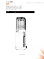
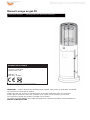
Manual Lounge heater (EN)
Handleiding Lounge heater (NL)
Handbuch Lounge heizung (DE)
Manual Lounge au gaz (FR)
LH15 - Lounge heater
www.sunred.nl

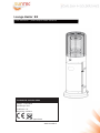
Lounge Heater EN
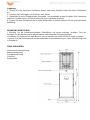
TECHNISCHE SPECIFICATIES
Wattage: 11.000 Watt
Element type: Gas
Certificates: CE,
Dimensions: H136cm
All measurements are approximate
User instructions - please keep for future references
www.sunred.nl

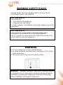
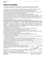
WARNlNG SAFETY RULES
PLEASE READ THE FOLLOWING SAFETY RULES PRlOR
TO OPERATION OF THE HEATER
FOR YOUR SAFETY
If you smell gas:
1ˊShut off gas to the appliance.
2ˊExtinguish any open flame.
3ˊIf odor continues, immediately call your gas supplier or your fire
Department.
FOR YOUR SAFETY
1.
Do not store or use gasoline or other flammable vapors
and liquids in the vicinity of this or any other applianceˊ
2.
An LP cylinder not connected for use shall not be stored in the
vicinity of this or any other applianceˊ
WARNlNG
1)
For use outdoors or in amply ventilated areas.
2)
An amply ventilated area must have a minimum of 25 % of the
surface area open.
3)
The surface area is the sum of the walls surface.
WARNING˖Improper installation, adjustment, alteration, service
or maintenance Can cause injury or property damage. Read the
installation, operating and maintenance instructions thoroughly
before installing or servicing this equipment.
www.sunred.nl

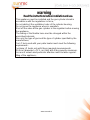
warning
Readtheinstructionsbeforeinstallationanduse.
-This appliance must be installed and the gas cylinder stored in
accordance with the regulations in force;
-Do not obstruct the ventilation holes of the cylinder housing;
-Do not move the appliance when in operation;
-Shut off the valve at the gas cylinder or the regulator before moving
the appliance;
-The tubing or the flexible hose must be changed within the
prescribed intervals;
-Use only the type of gas and the type of cylinder specified by the
manufacturer;
The LP tank used with your patio heater must meet the following
requirements:
Purchase LP tanks only with these required measurements:
(30.5cm) (diameter) x 57.1 cm) (tall) with 23kg capacity maximum.
-In case of violent wind particular attention must be taken against
tilting of the appliance;
www.sunred.nl

TABLE OF CONTENTS
Caution ……………………………………………………….
1
Heater Stand and Location …………………………………
2
Gas Requirements …………………………………………..
2
Leakage Test …………………………………………………
2
Operation and Storage ……………………………………...
3
Cleaning and Care …………………………………………..
4
Parts and Specifications ..…………………………………..
4
Assembly Parts and Procedures …………………………..
6
Problems Check List ………………………………………...
11
www.sunred.nl

CAUTION
PLEASE READ CAREFULLY THE FOLLOWING SAFETY GUIDELINES BEFORE OPERATION.
Do not use the patio heater for indoors, as it may cause personal injury or property damage.
This outdoor heater is not intended to be installed on recreational vehicles and/or boats.
Installation and repair should be done by aqualified service person.
Improperinstallation, adjustment, alteration can cause personalinjury or propertydamage.
Do not attempt toalter the unit in any manner.
Never replace or substitute the regulator withanyregulator otherthan the factory
-suggested replacement.
Do not store or use gasoline or other flammable vapors or liquids in the heater unit.
The whole gas system, hose, regulator, pilot or burner should be inspected for leaks or damage before
use, and at least annually by a qualified service person.
All leak tests should be done with a soap solution. Never use an open flame to check for leaks.
Do not use the heater until all connections have been leak tested.
Turnoff the gas valve immediately if smell of gas is detec
ted. Turn Cylinder Valve OFF.If leak is at Hose/
Regulator connection: tighten connection andperform another leak test. Ifbubbles continue appearing
should be returned to hose’s placeof purchase. If leak is at Regulator/Cylinder Valve connection: disconnect,
reconnect, andperform another leak check. If you continue to see bubbles after several attempts, cylinder
valve is defective and should be returned to cylinder’s place of purchase.
Do not transport heater while it’s operating.
Do not move the heater after it has been turned off until the temperature has cooled down.
Keep the ventilation opening of the cylinder enclosure free and clear of debris.
Do not paint the radiant screen, control panel or top canopy reflector.
Control compartment, burner and circulation air passageways of theheater must be kept clean.
Frequent cleaning maybe required as necessary.
The LP tank should be turned off when the heater is not in use.
Check the heater immediately if any of the following occurs:
-
The heater does notreach temperature.
-
The burner makes popping noise during use (a slight noise is normal when the burner is extinguished).
-
Smell of gas in conjunction with extreme yellow tipping of the burner flames.
The LP regulator/hose assembly must be located out of pathways where people may trip over it orin
area where the hose will not be subject to accidental damage.
Any guard or other protective device removed for servicing the heater must be replaced before operating the heater.
Adults and chi
ldren should stayawayfrom high temperaturesurface to avoid burns or clothingignition.
Children should becarefully supervised when they are in the area of the heater.
Clothing or other flammable materials should not behung on the heater or placed on or near the heater.
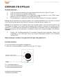
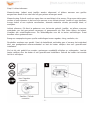
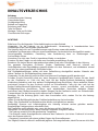
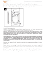
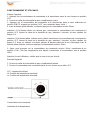
To change the gas cylinder in a amply ventilated area, away from any ignition
source (candle, cigarettes, other flame producing appliances, ...);
To check that the regulator seal is correctly fitted and able to fulfill itsfunction
showed as photo right;
To not obstruct the ventilation holes of the cylinder housing;
seal
hose
regulater
cylinder
To close the gas supply at the valve of the gas cylinder orthe regulator after use;
In the event of gas leakage, the appliance shall not be used or if alight, the gas supply
shall be shut off and the appliance shall be investigated andrectified before it is used again;
Hose/Regulatorconnection and
Regulator/Cylinderconnection
To check the hose at least once per month
ˈ
each time the cylinder is changed
ˈ
or each time before long time no use.
If it shows signs of cracking, splitting or other deterioration it shall be exchanged for new hose of the same length and of the
www.sunred.nl
s
s
ea
ea
l
l
ho
s
e
r
e
g
u
l
a
t
e
r
cy
l
i
n
de
r

equivalentquality;
The use of this appliance in enclosed areas can be dangerous and is PROHIBITED;
Read theinstructions before using thisappliance. The appliance must be installed in accordance with the instructions and
localregulations.
For connection of hose andregulator,and connection of regulator and hose, pleaserefer to photoshowedabove.
www.sunred.nl

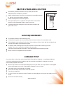
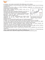
HEATER STAND AND LOCATION
The heater is primarilyfor outdoor use only. Always ensure that
adequate fresh air ventilation is provided.
Always maintain proper clearance to
non protected combustible materials
i.e. top 100 cm and sides 100 cm minimum.
Heater must be placed on level firm ground.
Never operate heater in an explosive atmosphere like in areas where
gasoline or other flammable liquids or vapors are stored.
To protect heater from strong wind, anchor the base securely to the
ground with screws.
100 cm
CEILING
GAS REQUIREMENTS
Use propane, butane or their mixtures gas only.
The pressure regulator and hose assembly to be used must conform to local standard codes.
The installation must conform to local codes, or in the absence of local codes, with the standard for the
storage and handling of liquid petroleum gases.
A dented, rusted or damaged tank maybe hazardous and should be checked by your tank
supplier. Never use a tank with a damaged valve connection.
The tank must be arranged to provide for vapor withdrawal from the operating cylinder.
Never connect an unregulated tank to the heater.
LEAKAGE TEST
Gas connections on the heater are leak tested at the factory prior to shipment. A complete gas tightness
check must be performed at the installation site due to possible mishandling in shipment or excessive
pressure being applied to the heater.
Make a soap solution of one part liquid detergent and one part water. The soap solution can be applied
with a spray bottle, brush or rag. Soap bubbles will appear in case of a leak.
The heater must be checked with a full cylinder.
Make sure the safety control valve is in the OFF position.
Turn the gas supply ON.
In case of a leak, turn off the gas supply. Tighten any leaking fittings, then turn the gas supply on and re-
check.
Never leak test while smoking.
www.sunred.nl

1.
Depress and turn control knob clockwise to OFF position.
2.
Fully open gas valve.
3.
Depress control knob and turn knob counter-clockwise to IGNITE position, then to PILOT position
(you will hear 2 clicks).
4.
With the pilot light lit, keep control knob depressed for 30 seconds.
NOTE: If the pilot light has not ignited, turn heater control knob to OFF position, fully close gas valve,
wait 5 minutes, then repeat steps 2–4 of the Lighting Instructions.
NOTE: If the pilot light ignites but does not stay lit, turn heater control knob to OFF position, fully close
propane gas valve, wait 5 minutes, then repeat steps 2–3. Now, using a lighter, ignite the pilot light
through the ignition hole on the emitter screen. Once the pilot light is lit, depress control knob for
30 seconds.
5.
After depressing the control knob for 30 seconds, turn control knob to LOW. To increase the
temperature, turn towards HIGH.
Warning˖check that no broken on the glass is found before operation.
1.
Fully close gas valve.
2.
Turn control knob clockwise to OFF position.
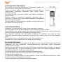
Variable control knob
Pointer
OFF
Off: the heater stop work
Hi: maximum temperature position
Lo: minimum temperature position
regulator
www.sunred.nl

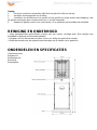
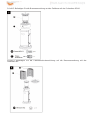
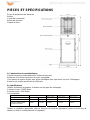
880 mm
1360 mm
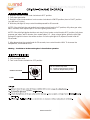
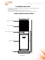
CLEANING AND CARE
•
Wipe off powder coated surfaces with soft, moist rag. Do not clean heater with cleaners that
are combustible or corrosive.
•
Remove debris from the burner to keep it clean and safe for use.
•
Cover the burner unit with the optional protective cover when the heater is not in use.
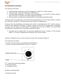
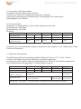
PARTS AND SPECIFICATIONS
370 mm
Flame screen guard
Burner assembly
Base of control housing
Tank housing
Base
460 mm
www.sunred.nl

A.
Constructionand characteristics
Transportable terrace/garden heater with tank housing.
Casing in steel with powder-coating or in stainless steel.
Gas hose connections with metal clamp (screw caps for Germany).
Heat emission from reflector.
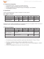
B.
Specifications
Use propane,butane or their mixtures gas only.
Max. wattage: 11000 watts
Min. wattage: 5000 watts
Consumption:
APPLIANCECATEGORY:
I
3+(28-30/37)
I
3B/P(30)
I
3B/P(50)
I
3B/P(37)
TYPESOF GAS:
Butane Propane
Butane, propane
or their mixtures
Butane, propane
or their mixtures
Butane, propane
or their mixtures
GASPRESSURE:
28-30mbar 37 mbar 30 mbar 50mbar 37mbar
OUTLETPRESSURE
OFREGULATOR:
30mbar 30 mbar 30mbar 50mbar 37mbar
Using the proper regulator according to outlet pressure of regulator as showed in the table above.
C.
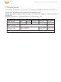
Table of injector
APPLIANCECATEGORY:
I
3+(28-30/37)
I
3B/P(30)
I
3B/P(50)
I
3B/P(37)
TYPESOF GAS:
Butane Propane
Butane, propane
or their mixtures
Butane, propane
or their mixtures
Butane, propane
or their mixtures
GASPRESSURE:
28-30mbar 37 mbar 30 mbar 50mbar 37mbar
TOTALHEAT
INPUT (Hs): (Qn)
11kW (800g/h)
12kW (870g/h)
INJECTOR SIZE:
1.51 mm for main burner
0.22 mm for pilot burner
1.38 mm for main burner
0.22 mmfor pilot burner
1.50 mm for main burner
0.22 mm for pilot burner
The markingˈfor exampleˈ1.51 on the injectorˈindicates that the size of injector is 1.51mm
The hose and regulator assembly must conform to local standard codes.
Regulator outlet pressure should meet the corresponding appliance category in B. Specification.
The appliance requires approved hose in 0.4m length.
www.sunred.nl

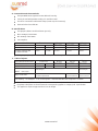
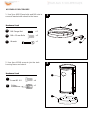
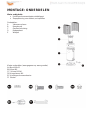
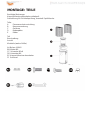
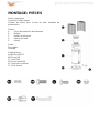
ASSEMBLY PARTS
Tools needed:
Philips screwdriver w/ medium blade
Spray bottle of soap solution for leakage test
Parts List:
Flame screen guard
A
Burner assembly
B
Cylinder Housing
C
Base
D
E
Wheel
PART DESCRIPTION QUANTITY
A
Flame screen guard
1
B
Burner assembly
1
C
Cylinder Housing
1
D
Base
1
E
Wheel
1
A
B
C
D
E
A
B
C
D
E

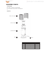
ASSEMBLY PARTS
HARDWARE CONTENTS (shown actual size)
AA BB
Bolt M8 X 15
Qty.2
M8
Flange
nut
Qty.2
CC
Screw M5 X 8
Qty.8
DD
M6 Dome Nut
Qty.1
EE
Philips
screwdriver
Qty.1
FF
Wrench
Qty.1
AA
CC
DD
EE FF
BB

1
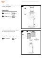
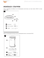
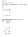
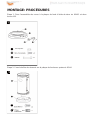
ASSEMBLY PROCEDURES
1. Use 2pcs M8X15mm bolts and M8 nuts to
connect bracket with wheel to the base.
Hardware Used
D
AA
BB
M8 x 15 mm Bolts x 2
FF
Wrench x 1
E
BB
2. Use 4pcs M5X8 screw to join the tank
2
housing base and stand.
Hardware Used
C
CC
Screw M5 X 8
x 4
EE
Philips
x 1
screwdriver
CC
M8 Flange Nut
AA
BB
FF
D
AA
E BB
CC
CC
1
2
C
EE
x 2

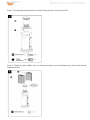
3
4
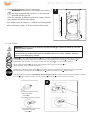
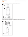
3. Use 4pcs M5X8 screw join the burner head
and tank housing body.
B
Hardware Used
CC
Screw M5 X 8
x 4
CC
EE
Philips
x 1
screwdriver
4. Use the M6 Dome Nut connect the two
DD
half safety guards to burner head.
A
Hardware Used
DD
M6 Dome Nut
x 1
B
B
C
C
C
C
C
C
C
C
C
C
C
C
C
C
C
C
C
C
C
C
C
C
A
A
A
A
A
A
3
4
CC
EE
DD
DD
B
CC
A

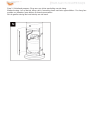
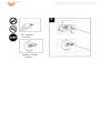
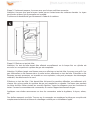
5. Propane Only-Proper Hose Connection.
WARNING! Ensure the hose does not contact
6
any high temperature surfaces, or it may melt
and leak causing a fire.
After the cylinder is placed inside the heater, secure
thecylinderwithblockbelttightly.
Theheatermustbefixedonastableandstrongtable
with a minimum height of 40cm from the floor level.
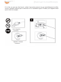
6. Leak Check.
WARNING!
A leak test must be performed annually and each me a cylinder is hooked up or if a part
of the gas system is replaced.
WARNING! Never use an open ŇĂme to check for gas leaks. Be certain no sparks or open ŇĂmes are
in the area while you check for leaks. Sparks or open ŇĂmes will result in a Įre or explosion, damage to
property, serious bodily injury, or death.
Leak tes ng: This must be done before ini al use, annually,and whenever any gas Components are replaced
or serviced. Do not smoke while performing this test, and remove all sources of igni
on. See Leak Tes ng
Diagram for areas to check. Turn all burner controls to the oī posi on. Turn gas supply valve on.
Brush a half-and-half solu on of liquid soap and water onto all joints and connec ons
of the regulator, hose, manifolds and valves.
Bubbles will indicate a gas leak. Either hten the loose joint or have the part replaced with one recommended
by the Customer Care department and have the pa
heater inspected by a cer ed gas installer.
If the leak cannot be stopped, immediately shut oī the gas supply, disconnect it,and have the pa o heater inspected
by a cer
ed gas installer or dealer. Do not use the pa heater un the leak has been corrected.
7
Hose / Regulator
connec
on
Regulator / Cylinder
connec
on
5
6

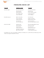
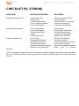
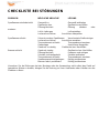
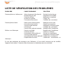
PROBLEMS CHECK LIST
PROBLEM
Pilot will not light
PROBABLE CAUSE
Gas valve may be OFF
SOLUTION
Turn the gas valve ON
Tank fuel empty Refill LPG tank
Opening blocked Clean or replace opening
Air in supplysystem
Looseconnections
Purge air from lines
Check all fittings
Pilot will not stay on
Debris around pilot
Clean dirty area
Looseconnections
Thermocouplebad
Tightenconnections
Replacethermocouple
Gas leak in line Check connections
Lack of fuel pressure Tank near empty. Refill LPG tank.
Burner will not light
Pressure is low
Tank near empty. Refill LPG tank.
Opening blocked Remove and clean
Control not ON
Thermocouplebad
Turn valve to ON
Replacethermocouple
Pilot light assembly bent Place pilot properly
Not in correct location Position properly and retry
If the appliance is in case of any defaults or problems of assembly or useˈplease don’t try to modify it by yourselfˈ
contact your supplier or distributor to solve it.

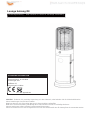
Lounge Heater NL
Wattage: 11.000 Watt
Element type: Gas
Certificaten: CE
Afmeting: H136cm
BELANGRIJK – Verwijder zorgvuldig de verpakking voor gebruik, maar bewaar de veiligheidsinstructies.
Deze instructies maken deel uit van het product.
Gelieve nota te nemen van alle veiligheidswaarschuwing die in deze handleiding vermeldt worden.
Lees de instructies in hun geheel door en bewaar deze voor toekomstig gebruik.
Deze instructies dienen te worden bewaard met het product.
Dit product is voor huishoudelijk gebruik en mag niet commercieel of voor contractdoeleinden worden gebruikt.
Gebruikershandleiding – Bewaar voor eventueel toekomstig gebruik

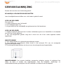
GEBRUIKSAANWIJZING
Bewaar de instructies voor toekomstig gebruik
BELANGRIJK: VEILIGHEIDSVOORSCHRIFTEN
Lees de veiligheidsvoorschriften voor u de heater in gebruik neemt
VOOR UW VEILIGHEID
Als u gas ruikt:
1. Sluit de gastoevoer naar het toestel.
2. Doof eventueel open vuur.
3. Als geur blijft, bel dan onmiddellijk uw gasleverancier of de brandweer.
VOOR UW VEILIGHEID
1. Bewaar of gebruik geen benzine of andere ontvlambare gassen en vloeistoffen in de nabijheid
van dit of een ander apparaat.
2. Een niet aangesloten gasfles mag niet in buurt van dit of een ander apparaat worden
opgeslagen.
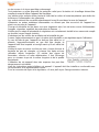
WAARSCHUWING
1) Voor gebruik buiten of in voldoende geventileerde ruimtes.
2) Een voldoende geventileerde ruimte houdt in dat minimaal 25% van de omringende
oppervlakken geopend zijn.
3) De omringende oppervlakken zijn de som van de omringende wand-oppervlaktes.
WAARSCHUWING: Een onjuiste installatie, aanpassing, wijziging, service of onderhoud kan
leiden tot letsel of schade aan eigendommen. Lees de installatie-, bedienings- en
onderhoudsinstructies grondig door vóór de installatie of onderhoud van dit apparaat.

WAARSCHUWING
Lees de instructies voor installatie en gebruik.
-Dit apparaat moet worden geïnstalleerd en de gasfles opgeslagen in overeenstemming met de
geldende voorschriften.
-De ventilatiegaten van de gasflesbehuizing niet afdekken.
-Verplaats het apparaat niet tijdens gebruik.
-Sluit het ventiel van de gasfles of de regelaar voor u het apparaat verplaatst.
-De leiding of de flexibele slang moet binnen de voorgeschreven intervallen worden vervangen.
-Gebruik alleen het type gas en gasfles dat door de fabrikant voorgeschreven wordt.
-De gasfles moet aan de volgende eisen voldoen: Afmeting 30,5cm diameter, 57,1cm hoogte,
23kg capaciteit.
-In geval van harde wind dient u ervoor te zorgen dat het apparaat niet kantelt en omvalt.
Seite wird geladen ...
Seite wird geladen ...
Seite wird geladen ...
Seite wird geladen ...
Seite wird geladen ...
Seite wird geladen ...
Seite wird geladen ...
Seite wird geladen ...
Seite wird geladen ...
Seite wird geladen ...
Seite wird geladen ...
Seite wird geladen ...
Seite wird geladen ...
Seite wird geladen ...
Seite wird geladen ...
Seite wird geladen ...
Seite wird geladen ...
Seite wird geladen ...
Seite wird geladen ...
Seite wird geladen ...
Seite wird geladen ...
Seite wird geladen ...
Seite wird geladen ...
Seite wird geladen ...
Seite wird geladen ...
Seite wird geladen ...
Seite wird geladen ...
Seite wird geladen ...
Seite wird geladen ...
Seite wird geladen ...
Seite wird geladen ...
Seite wird geladen ...
Seite wird geladen ...
Seite wird geladen ...
Seite wird geladen ...
Seite wird geladen ...
Seite wird geladen ...
Seite wird geladen ...
Seite wird geladen ...
Seite wird geladen ...
Seite wird geladen ...
Seite wird geladen ...
Seite wird geladen ...
Seite wird geladen ...
-
 1
1
-
 2
2
-
 3
3
-
 4
4
-
 5
5
-
 6
6
-
 7
7
-
 8
8
-
 9
9
-
 10
10
-
 11
11
-
 12
12
-
 13
13
-
 14
14
-
 15
15
-
 16
16
-
 17
17
-
 18
18
-
 19
19
-
 20
20
-
 21
21
-
 22
22
-
 23
23
-
 24
24
-
 25
25
-
 26
26
-
 27
27
-
 28
28
-
 29
29
-
 30
30
-
 31
31
-
 32
32
-
 33
33
-
 34
34
-
 35
35
-
 36
36
-
 37
37
-
 38
38
-
 39
39
-
 40
40
-
 41
41
-
 42
42
-
 43
43
-
 44
44
-
 45
45
-
 46
46
-
 47
47
-
 48
48
-
 49
49
-
 50
50
-
 51
51
-
 52
52
-
 53
53
-
 54
54
-
 55
55
-
 56
56
-
 57
57
-
 58
58
-
 59
59
-
 60
60
-
 61
61
-
 62
62
-
 63
63
-
 64
64


SunRed DF15 Benutzerhandbuch
- Typ
- Benutzerhandbuch
- Dieses Handbuch eignet sich auch für
in anderen Sprachen
- English: SunRed DF15 User manual
- français: SunRed DF15 Manuel utilisateur
- Nederlands: SunRed DF15 Handleiding
Verwandte Artikel


Andere Dokumente
-
Hendi 272404 Benutzerhandbuch
-
Perel FT15C-FR Benutzerhandbuch
-
Tristar KA-5339 Benutzerhandbuch
-
DeWalt DXPH125E Benutzerhandbuch
-
Hendi 272701 Benutzerhandbuch
-
Tristar KA-5340 Benutzerhandbuch
-
-
-
Perel FT5130 Benutzerhandbuch
-