
User and Maintenance
Instructions
Vapour Grill
(Gas)
Handleiding Voor
Bediening En Onderhoud
Waterige Gril
(Gas)
Betriebs- und
Wartungsanleitung
Wassergrill
(Gasbetrieb)
Manuel d’Utilisation et
de Maintenance
Gril Avec Bac
A Eau
(A Gaz)

2
Table of Contents / Inhoudsopgave /
Inhaltsverzeichnis / Table des Matières
I. ENGLISH ………………………………………………………………. 3
A. Description
B. Products
C. Mounting Instructions
D. Operator Instructions and Attention Points
E. Figures
F. Product Drawings
II. NEDERLANS ………………………………………………………… 13
A. Beschrijving
B. Producten
C. Montage-Instructies
D. Instructies van de bediener en aandachtspunten
E. Figuur
F. Producttekeningen
III. DEUTSCH ……………………………………………………………. 23
A. Beschreibung
B. Produkte
C. Installationsanleitung
D. Benutzerhinweise und zu Beachtende Punkte
E. Abbildung
F. Produktzeichnungen
IV. FRANÇAIS …………………………………………………………… 33
A. Explications
B. Des Produits
C. Instructions de Montage
D. Instructions a L’utilisateur et Points a Considérer
E. Les Figures
F. Dessins des Produits

3
User and Maintenance
Instructions
Vapour Grill (Gas)

4
A. DESCRIPTION
Our dear customer,
Your preferred COMBISTEEL is nature and technology friendly. We thank you for your
choice.
COMBISTEEL has been produced with the understanding of "Total Quality" in modern
production facilities.
Important Safety Information
Carefully read this guide and keep it for future review.
WARNING: Installation of the devices must be done by an authorized service person.
WARNING: Equipment must be grounded.
Indicates that there is a risk of personal injury or property damage.
Explosion / fire hazard
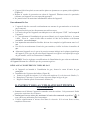
B. PRODUCTS
C. MOUNTING INSTRUCTION
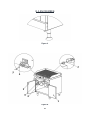
Placement
Installation and adjustment of the device should be carried out by experienced technical
staff.
Place the device at least 10 cm away the side walls.
Place the device beneath a filtered exhaust hood in order to eliminate smell and fume
that may be emitted during cooking.
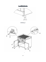
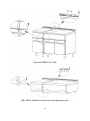
Device should be placed on a flat surface by suitably balancing on the four adjustable
legs. (Figure A)
Remove the protective nylon on the device. Clean the adhesive particles left on the
device with a suitable cleaner.
Never leave flammable material near the device.
CODE
DESCRIPTION
SERIE
7178.0505
Gas vapour grill, cast plate
700
7178.3210
Gas vapour grill, cast plate
900
7178.3215
Gas vapour grill, cast plate
900

5
Gas Connection
Device should be connected in accordance with the national and local gas standards of
the relevant country.
The device should not be directly connected to the tube.
Gas inlets "GAS" of the device are indicated with a label on device body.
Connection to the gas installation should be made with flex pipe and ball valve. Fix the
said ball valve to a place that is away from heat and easily accessible in case of a danger.
Flex connection pipe should be preioudically replaced every 5 years.
After gas inlet connection is completed, check for possible gas leakages.
Feed the device with the gas and pressure as specified on device information plate and
adjusted. If the gas type to which the device was adjusted for is not suitable to the gas
type at the mounted place, follow the instructions written below.
ATTENTION: All adjustments and modifications to be performed on the gas installation and
connection of the device should be performed by authorized people.
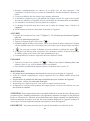
ADJUSTMENT ACCORDING TO DIFFERENT GAS TYPES
If the device is connected to gas installation, close main gas inlet valve.
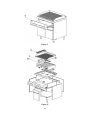
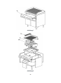
Replacement of top burner nozzles (Figure B)
a. Remove cooker grater (1), top burner cover (2) and oil tray (3)
b. Replace nozzle (5) with a nozzle suitable for the gas type
c. Adjust the flame of the pilot burner by turning the bolt (4)
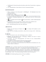
D. OPERATOR INSTRUCTIONS AND ATTENTION POINTS
Make sure to turn the device on and wait before attempting to cook. This will ensure the
evaporation of the protective oil on top.
When you do not cook, keep the adjustment button on " " position. It will provide a
more economical usage for you
Check the water level in the drawer periodically. Replace the water if the water level is
down.
Clean the grill mouldings everyday with a suitable tool. This will help clean the
carbonized and burned food residues and will ensure the cooking efficiency.
Oil cabinet should be cleaned after usage each time.
If the buyer intends not to use the grill for a long period of time, the grill mouldings
should be oiled and stored in a place with no humidity.
The back-side chimneys should not be blocked at any time.
The water-oil mixture can be discharged from the discharge valve at the back of the
device.
No food should be left at the cabinet part of the unit.
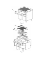
START-UP
Put water in the water cabinet (7) (Figure C) – 5lt. Do not start-up with no water inside.
Turn on the main gas valve.
Put the grill gas button (5) to " " position.

6
At this position fire up the pilot (6). After firing up the pilot keep pressure on the botton
at least 10 seconds to make sure the thermocupul is heated up.
You can adjust the flames to the reuired level by toggling " " or " " signs
If the device is operated for the first time, keep the button pressed at pilot burner flame
position for a while before ignition to discharge the air in the gas installation.
Top surface temerature should be smaller than K80
TURNING OFF
Turn the button (6) to position " " .Then it will be just the pilot flame is lit
To fully turn the device off, get the indicator to "0" sign.
MAINTENANCE
Never perform maintenance without closing the main gas valve of the device.
Before it cools down completely, wipe the device with a cloth immersed in warm soapy
water.
Do not use cleaning substances and tools that may cause scratches on device surface.
If required, use chemical cleaners.
Do not clean the device with pressurized water or vapour.
If the device will not be used for a long time, coat the surfaces with a thin layer of
Vaseline.
ATTENTION: Any part replacement that may affect safety must be carried out by the
authorized people. During maintenance and repair, keep the main gas valve closed and keep
away fire. Always perform leakage check after repair or part replacement; use foam or gas
detector for this aim. In case of any dangerous condition with the device, notify to the authorized
service. Do not allow unauthorized people to interfere in the device.
DANGEROUS: Never allow leakage check to be performed with flame.

7
Compatibility Information
This device is designed and manufactured in accordance with the following directives and
standards.
marking directive, 93/68/EEC
TS EN 203-1 / Gas Powered Cooking Appliances – Part 1:General Safety Appliances
TS EN 203-2-1 Gas Fired Catering Equipments - Part 2-1: Specifications – Open-tops
TS EN 203-2-2 Gas Burning Devices – Part 2-2: Special Rules – Ovens
Limitation of Liability: All technical information contained in this manual, operating
instructions, operation and maintenance of the device, contains the latest information on your
device. The manufacturer accepts no responsibility for damage or injury which may result
from failure to follow the instructions in this manual, use outside of the intended use,
unauthorized repair, unauthorized modifications to the device, or use of spare parts not
approved by the manufacturer.

8
E. FIGURES
Figure A
Figure B

9
Figure C
Figure D

10
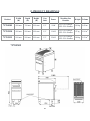
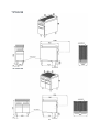
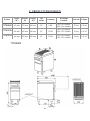
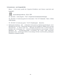
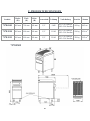
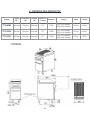
F. PRODUCT DRAWINGS
7178.0505
Product
Width
(W)
Depth
(D)
Height
(H)
Gas
Inlet
Power
Working Gas
Pressure
Weight
Volume
7178.0505
400 mm
700 mm
900 mm
1/2"
9 kW
NG-G20-20mBar
LPG-G30-30mBar
103 kg
0.45 m3
7178.3210
400 mm
900 mm
900 mm
1/2"
11 kW
NG-G20-20mBar
LPG-G30-30mBar
87 kg
0.56 m3
7178.3215
800 mm
900 mm
900 mm
1/2"
22 kW
NG-G20-20mBar
LPG-G30-30mBar
194 kg
1.05 m3

11
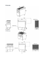
7178.3210
7178.3215

12
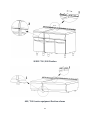
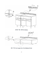
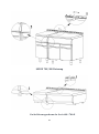
SERIE 700 / 900 Fixation
600 / 700-S series equipment fixation scheme

13
Handleiding Voor Bediening
En Onderhoud
Waterige Gril (Gas)

14
A. BESCHRIJVING
Beste klanten,
Uw gewenste COMBISTEEL-product is natuur- en technologievriendelijk. Wij danken u
voor uw keuze.
COMBISTEEL is vervaardigd met het begrip '' Volledige Kwaliteit ''in zijn moderne
productiefaciliteiten.
Belangrijke veiligheidsinformatie
Lees deze handleiding aandachtig door en bewaar deze voor toekomstige
beoordelingen.
WAARSCHUWING: De apparaten moeten worden geïnstalleerd door een
gekwalificeerdeonderhoudsmonteur.
WAARSCHUWING: De apparatuur moet worden geaard.
Geeft aan dat er een risico bestaat op persoonlijk letsel of materiële schade.
Explosie / brandgevaar.
B. PRODUCTEN
C. MONTAGE-INSTRUCTIES
INSTALLATIE INSTRUCTIES
Installatie en afstelling van het apparaat moet worden uitgevoerd door de technische
dienst van de erkende servicedienst.
Plaats het apparaat op minstens 10 cm afstand van de muurrand.
CODE
BESCHRIJVING
SERIE
7178.0505
Gas watergrill, gegoten plaat
700
7178.3210
Gas watergrill, gegoten plaat
900
7178.3215
Gas watergrill, gegoten plaat
900

15
Plaats het apparaat onder een gefilterde afzuigkap om alle geuren en dampen te
verwijderen die vrijkomen tijdens het koken.
Het apparaat moet op een vlak oppervlak worden geplaatst, op de juiste manier afgesteld
op de vier verstelbare poten. (Zie figuur A)
Verwijder de beschermende nylonlaag op het apparaat. Verwijder eventuele plakkerige
deeltjes op het apparaat met een geschikte reiniger.
Laat nooit ontvlambaar materiaal achter rond het apparaat.
GAASANSLUITING
Het apparaat moet worden aangesloten in overeenstemming met de nationale en lokale
gasnormen van het betreffende land.
Het apparaat mag niet rechtstreeks op de buis worden aangesloten.
De gaspoorten van het apparaat worden aangegeven met de label "GAS" op de behuizing
van het apparaat.
De verbinding met de gasinstallatie moet worden gemaakt met een flexibele buis en
kogelklep. Bevestig de kogelkraan op een plaats uit de buurt van hitte en gemakkelijk
toegankelijk in geval van gevaar.
Flexibele verbindingsleidingen moeten om de 5 jaar regelmatig worden vervangen.
Nadat de gasinlaataansluitingen zijn voltooid, controleer mogelijke gaslekken.
Voorzie het apparaat van gas en druk zoals aangegeven op het typeplaatje van het
apparaat. Als het type gas waarop het apparaat is ingesteld niet overeenkomt met het
geïnstalleerde type gas, volg dan de onderstaande instructies.
WAARSCHUWING: Alle aanpassingen en aanpassingen aan de gasinstallatie en
apparaataansluiting moeten worden uitgevoerd door bevoegde personen.
AANPASSING AAN VERSCHILLENDE GAS TYPES
Als het apparaat op de gasinstallatie is aangesloten, sluit dan de hoofdgasinlaatklep.
Installatie van de branderuitlaat (Figuur B)
a. Verwijder de kookplaat (1), de bovenste kookklep (2) en de oliecarter (3).
b. Vervang het mondstuk (5) met een mondstuk dat geschikt is voor het type gas.
c. Pas de vlam van de waakvlam aan door de bout (4) te draaien.
D. INSTRUCTIES VAN DE BEDIENER EN
AANDACHTSPUNTEN
Zorg ervoor dat u het apparaat geopend heeft en wacht daarna voordat u gaat koken. Dit zal
ervoor zorgen dat de bovenste beschermende olie gaat verdampen.
Houd de bedieningsknop " " in de stand terwijl u niet aan het koken bent. Dit zal voor u
zorgen voor een zuiniger gebruik
Controleer het waterpeil in de tank regelmatig. Als het waterniveau laag is, vul dan opnieuw.
Reinig de grill ruimtes dagelijks met een geschikt gereedschap. Dit zal ervoor zorgen dat de
kookefficiëntie stijgt door verkoolde en verbrande voedselresten te verwijderen.

16
De olietank moet na elk gebruik worden schoongemaakt.
Als de koper van plan is om de grill gedurende langere tijd niet te gebruiken, moeten
de grillruimten worden ingesmeerd met olie en worden bewaard in een vochtvrije
omgeving.
Schoorstenen aan de achterzijde mogen nooit worden geblokkeerd.
Het water-olie mengsel kan worden afgevoerd via de afvoerklep aan de achterkant van het
apparaat.
Er mag geen voedsel in het kast gedeelte van het apparaat achterblijven.
BEGIN
Plaats water in de waterkast (7) (Figuur C) (7178.0505 5lt). Gebruik het apparaat niet
zonder water.
Open de hoofdgasklep
Draai de grill knop naar de " " positie.
Ontsteek de waakvlam (6) in deze positie. Nadat de pilot is afgevuurd, houdt de knop ten
minste 10 seconden ingedrukt om ervoor te zorgen dat het thermokoppel warm is.
" " Of gebruik de " " tekens om het vuur op het gewenste niveau in te stellen.
Als dit de eerste keer is dat het apparaat wordt gestart, houdt u de knop in de positie van
de waakvlam ingedrukt om lucht uit de gasinstallatie te verwijderen.
De oppervlaktetemperatuur moet lager zijn dan K80.
UITSCHAKELEN
Draai de knop naar positie " " (6). In dit geval brandt alleen de pilotvlam.
Als u het apparaat volledig wilt uitschakelen, trekt u de indicator naar het teken "0".
ONDERHOUD
Gebruik het apparaat nooit zonder de hoofdgasklep te sluiten.
Laat het apparaat volledig afkoelen voordat u het afveegt met een doek gedrenkt in warm
zeepsop.
Gebruik geen schoonmaakmiddelen die krassen op het oppervlak van het apparaat kunnen
veroorzaken.
Gebruik indien nodig chemische reinigingsmiddelen.
Maak het apparaat niet schoon met water of stoom.
Als het apparaat gedurende een lange periode niet wordt gebruikt, bedek dan de
oppervlakken met een dun laagje vaseline.
WAARSCHUWING: Elke vervanging van onderdelen die de veiligheid kan beïnvloeden, moet door
de bevoegde personen worden uitgevoerd. Houd tijdens onderhoud en reparatie de hoofdgasklep
gesloten en uit de buurt van vuur. Voer na elke reparatie of vervanging een lektest uit met een schuim-
of gasdetector. In geval van een gevaarlijke situatie met het apparaat, informeer de bevoegde service.
Laat een onbevoegde persoon niet ingrijpen op de apparaten.
GEVAARLIJK: Laat de lekcontrole nooit met vuur uitvoeren.

17
Informatie over compatibiliteit
Dit apparaat is ontworpen en vervaardigd in overeenstemming met de volgende richtlijnen
en normen.
markeringsrichtlijn, 93/68 / EEG
TS EN 203-1 / Op gas gestookte kooktoestellen –Deel 1: Algemene
veiligheidsvoorzieningen
TS EN 203-2-1 Verbrandingsapparatuur voor gasverbranding- Deel 2-1: -
Specificaties- Open-tops
TS EN 203-2-2 Gasverbrandingsapparatuur- Deel 2-2: - Speciale regels- Ovens
Aansprakelijkheidsbeperking: Alle technische informatie, bedieningsinstructies en
bedienings- en onderhoudsinformatie in deze handleiding bevatten de meest actuele
informatie over uw apparaat. De fabrikant aanvaardt geen aansprakelijkheid voor schade
of letsel veroorzaakt door het niet volgen van de instructies in deze handleiding, gebruik
van het apparaat voor het beoogde doel, ongeoorloofde reparatie of aanpassing of gebruik
van reserveonderdelen die niet zijn goedgekeurd door de fabrikant.

18
E. FIGUUR
Figuur A
Figuur B

19
Figuur C
Figuur D

20
F. PRODUCTTEKENINGEN
7178.0505
Product
Diepte
(W)
Breedte
(D)
Hoogte
(H)
Gas
Inlaat
Vermogen
Werkende
Gasdruk
Gewicht
Volume
7178.0505
400 mm
700 mm
900 mm
1/2"
9 kW
NG-G20-20mBar
LPG-G30-30mBar
103 kg
0.45 m3
7178.3210
400 mm
900 mm
900 mm
1/2"
11 kW
NG-G20-20mBar
LPG-G30-30mBar
114 kg
0.56 m3
7178.3215
800 mm
900 mm
900 mm
1/2"
22 kW
NG-G20-20mBar
LPG-G30-30mBar
220 kg
1.05 m3
Seite laden ...
Seite laden ...
Seite laden ...
Seite laden ...
Seite laden ...
Seite laden ...
Seite laden ...
Seite laden ...
Seite laden ...
Seite laden ...
Seite laden ...
Seite laden ...
Seite laden ...
Seite laden ...
Seite laden ...
Seite laden ...
Seite laden ...
Seite laden ...
Seite laden ...
Seite laden ...
Seite laden ...
Seite laden ...
Seite laden ...
-
 1
1
-
 2
2
-
 3
3
-
 4
4
-
 5
5
-
 6
6
-
 7
7
-
 8
8
-
 9
9
-
 10
10
-
 11
11
-
 12
12
-
 13
13
-
 14
14
-
 15
15
-
 16
16
-
 17
17
-
 18
18
-
 19
19
-
 20
20
-
 21
21
-
 22
22
-
 23
23
-
 24
24
-
 25
25
-
 26
26
-
 27
27
-
 28
28
-
 29
29
-
 30
30
-
 31
31
-
 32
32
-
 33
33
-
 34
34
-
 35
35
-
 36
36
-
 37
37
-
 38
38
-
 39
39
-
 40
40
-
 41
41
-
 42
42
-
 43
43


in anderen Sprachen
- English: CombiSteel 7178.3210 User manual
- français: CombiSteel 7178.3210 Manuel utilisateur
- Nederlands: CombiSteel 7178.3210 Handleiding
Verwandte Papiere


Sonstige Unterlagen
-
Evolve E80CBG04 Instruction, Use And Maintenance Manual
-
Hoover HVG6DSB Benutzerhandbuch
-
-
-
ROSIERES RDK74MBB/1 Benutzerhandbuch
-
-
Candy CDK6GF4WEKB Benutzerhandbuch
-
Vetus PD1000 Benutzerhandbuch
-
GGM Gastro MELJ322N Bedienungsanleitung