
11/05/2007 Rev. 3 160489
ISTRUZIONI PER L’INSTALLAZIONE, L’USO E LA MANUTENZIONE
INSTALLATION, USE AND MAINTENANCE INSTRUCTIONS
INSTRUCTIONS POUR L’INSTALLATION, L’EMPLOI ET L’ENTRETIEN
INSTALLATIONS-, BETRIEBS-UND WARTUNGSANLEITUNGEN
INSTRUCCIONES PARA LA INSTALACIÓN, EL USO Y EL MANTENIMIENTO
I
GB
F
D
E
FRIGGITRICE A GAS SERIE DOMINA
SECONDO NORMA: EN 437 e EN 203 parte 1 e 2 Categoria II per Gas Metano e G.P.L.
GAS FRYER DOMINASERIES
ACCORDING TO: EN 437 and EN 203 part 1 and 2 Cat. II for Natural gas and L.P.G.
FRITEUSE AU GAZ SERIE DOMINA
CONFORME AUX NORMES: EN 437 et EN 203 1ère et 2ème partie pour Gaz Méthane et G.P.L.
GASBEHEIZTE FRITEUSE SERIE DOMINA
NACH: EN 437 und EN 203 Teil 1 und 2 Kategorie II für Erdgas und Flüssiggas
FREIDORA A GAS SERIE DOMINA
SEGÚN: EN 437 y EN 203 parte 1 y 2. Categoría II: Metano y G.P.L.
GF49T GF99T
0 6 9 4

- 2 -
I
CAPITOLO DESCRIZIONE PAGINA
Avvertenze generali ............................................................................................................................. 3
1. Dati tecnici .......................................................................................................................................... 4
1.1 Friggitrice a gas serie Domina Cat. II (Gas metano e G.P.L.) ............................................................... 4
1.2 Caratteristiche tecniche ....................................................................................................................... 4
2. Istruzioni per l’installazione ............................................................................................................. 4
2.1 Informazioni riguardanti le friggitrici a gas serie Domina .................................................................. 5
2.2 Legge, norme e direttive tecniche da rispettare .................................................................................. 5
2.3 Luogo di installazione ........................................................................................................................ 5
2.4 Posizionamento ................................................................................................................................... 5
2.5 Tabella II: Dati tecnici gas, pressione, ugelli bruciatore, pilota e vite del minimo.
Apparecchio tipo: GF49T e GF99T con vasche da 18 litri ................................................................. 5
2.6 Colleagmenot all’impianto del gas ..................................................................................................... 6
2.6.1 Scarico dei prodotti di combustione ................................................................................................... 6
2.6.2 Apparecchi a gas tipo A ....................................................................................................................... 6
2.6.3 Come ottenere la portata termica nominale ........................................................................................ 6
2.7 Controllo della pressione .................................................................................................................... 6
2.8 Regolazione della portata termica minima ......................................................................................... 6
2.9 Controllo per il funzionamento a gas liquido .................................................................................... 6
2.9.1 Controllo del funzionamento .............................................................................................................. 7
2.10 Introduzione all’utente........................................................................................................................ 7
3. Trasformazione per funzionamento ad altro tipo di gas ................................................................ 7
3.1 Sostituzione ugello bruciatore principale .......................................................................................... 7
3.2 Regolazione bruciatore pilota ............................................................................................................ 7
4. Sostituzione dei componenti più importanti ....................................................................................7
5. Istruzioni per l’utente ........................................................................................................................ 8
5.1 Accensione pilota ................................................................................................................................ 9
5.2 Accensione del bruciatore principale e regolazione della temperatura ............................................. 9
5.3 Spegnimento ....................................................................................................................................... 9
5.4 Pulizia e accorgimenti ......................................................................................................................... 9
5.5 Limitatore di temperatura .................................................................................................................... 10
6. Manutenzione e pulizia ...................................................................................................................... 10
SCHEMA DI INSTALLAZIONE ......................................................................................................... 47
INDICE
ITALIANO ................................................................................................ pagina 2 - 10
ENGLISH ................................................................................................. page 11 - 19
FRANÇAIS ............................................................................................... page 20 - 28
DEUTSCH ................................................................................................ Seite 29 - 37
ESPAÑOL ................................................................................................ página 38 - 46

- 3 -
I
In caso di inosservanza delle norme contenute nel presente manuale, sia da parte dell’utente che da parte del tecnico
addetto all’installazione, la Ditta declina ogni responsabilità ed ogni eventuale incidente o anomalia causato dalle
suddette inosservanze non potrà essere imputato alla stessa.
LA CASA COSTRUTTRICE DECLINA OGNI RESPONSABILITÀ PER LE POSSIBILI INESATTEZZE CONTENUTE NEL PRE-
SENTE OPUSCOLO, IMPUTABILI AD ERRORI DI TRASCRIZIONE O STAMPA. SI RISERVA INOLTRE IL DIRITTO DI APPOR-
TARE AL PRODOTTO QUELLE MODIFICHE CHE SI RITENGONO UTILI O NECESSARIE, SENZA PREGIUDICARE LE CARAT-
TERISTICHE ESSENZIALI.
- Leggere attentamente le avvertenze contenute nel presente libretto in quanto forniscono importanti
indicazioni riguardanti la sicurezza di installazione, d’uso e di manutenzione.
- Conservare con cura questo libretto per ogni ulteriore consultazione dei vari operatori.
- Dopo aver tolto l’imballaggio, assicurarsi dell’integrità dell’apparecchiatura e in caso di dubbio, non utilizzare
l’apparecchiatura e rivolgersi a personale professionalmente qualificato.
- Prima di collegare l’apparecchiatura, accertarsi che i dati riportati sulla targhetta siano corrispondenti a quelli della
rete di distribuzione gas.
- Questa apparecchiatura deve essere destinata solo all’uso per il quale è stata espressamente concepita, ogni
altro uso è da considerarsi improprio e quindi pericoloso.
- L’apparecchiatura deve essere utilizzata solo da persona addestrata all’uso della stessa.
- Per eventuale riparazione rivolgersi solamente ad un centro di assistenza tecnica autorizzato dal costruttore e
richiedere l’utilizzo di ricambi originali.
- Il mancato rispetto di quanto sopra, può compromettere la sicurezza dell’apparecchiatura.
- Non lavare l’apparecchiatura con getti d’acqua diretti e ad alta pressione.
- Non ostruire le aperture o feritoie di aspirazione o di smaltimento del calore.
AVVERTENZE GENERALI

- 4 -
I
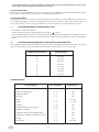
1.1 FRIGGITRICE A GAS SERIE DOMINA CAT. II (GAS METANO E G.P.L.)
1.2 CARATTERISTICHE TECNICHE
Struttura portante in acciaio inox AISI 304, pannellatura e basamento in acciaio inox montata su piedini regolabili in altezza.
VASCA in acciaio inox AISI 304. Con zona espansione olio
RISCALDAMENTO A GAS mediante bruciatori a fiamma autostabilizzata in ghisa che garantiscono un’elevata uniformità di
riscaldamento. Regolazione termostatica della temperatura con valvola di sicurezza e termocoppia per l’interruzione dell’afflus-
so del gas in caso di spegnimento accidentale del bruciatore pilota. Accensione piezoelettrica al pilota.
L’installazione e l’eventuale trasformazione per l’uso di altri tipi di gas, deve essere eseguita da persone qualificate
secondo la normativa in vigore.
Vedere tabelle dati tecnici: 1.1 e 2.5.
AVVERTENZE:
Nel caso in cui l’apparecchiatura venga installata contro una parete quest’ultima deve resistere ai valori di temperatura di
100°C e deve essere incombustibile, oppure l’apparecchiatura deve essere sistemata a 10 cm. di distanza.
Prima di procedere all’installazione, togliere dal rivestimento la pellicola di protezione in plastica, eliminando gli eventuali
residui adesivi con prodotto adatto alla pulizia per l’acciaio inossidabile.
Installare l’apparecchio in posizione orizzontale, la corretta posizione si otterrà ruotando i piedini livellatori.
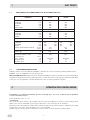
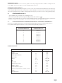
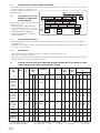
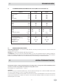
(1) Compresa la portata termica del bruciatore pilota ca. 400 W
MODELLO
Tipo
mm
mm
mm
mm
kg.
mm
mm
mm
1
mm
mm
mm
ca. min.
°C/min.
“A”
(1) kW
m
3
/h
(15°C)
g/h
m
3
/h
m
3
/h
GF49T
A
450
900
580
680
-
1
290
400
300
18
13,2
11,8
G3/4”
16,5
24,8
1301-1282
1,75
2,1
12
260 120
310 310
130 130
GF99T
A
900
900
580
680
-
2
290
400
300
18 + 18
13,2
11,8
G3/4”
33
49,5
2602-2564
3,5
4,2
24
260 120
310 310
130 130
1. DATI TECNICI
2. ISTRUZIONI PER L’INSTALLAZIONE
Dimensioni
Larghezza
Profondità
Altezza
Altezza totale
Peso netto
Dimensioni vasca e N°
Larghezza
Profondità
Altezza
Capacità vasca
Dimensioni e N° cestelli
Larghezza
Profondità
Altezza
Tempo preriscaldamento (160 K)
Attacco gas
Portata termica nominale
Aria per la combust. / ventil.
Consumo gas
G.P.L. G 30/31
Metano H-G 20
Metano L-G 25

- 5 -
I
2.1 INFORMAZIONI RIGUARDANTI LE FRIGGITRICI A GAS SERIE DOMINA
Questo libretto è valido per le nostre Friggitrici serie Domina del tipo A Categoria II (Gas naturale e Liquido G.P.L.).
Vedere tabella 1.1 - 2.5. La targhetta secondo le norme EN437 e EN 203 parte 1 si trova sotto il bordo inferiore del cruscotto.
2.2 LEGGE, NORME E DIRETTIVE TECNICHE DA RISPETTARE
Per l’installazione sono da osservare le seguenti norme:
- Prescrizioni vigenti antinfortunistiche e antincendio.
- La regolamentazione dell’ente erogatore del gas, dal quale bisogna farsi rilasciare il nullaosta prima dell’installazione.
- Norme «Installazione impianti a gas».
- Norme igieniche.
2.3 LUOGO D’INSTALLAZIONE
- L’apparecchio deve essere installato in locali con sufficiente areazione. Questo apparecchio richiede una aspirazione di
almeno 2 m
3
/h • kW P.T. (Portata Termica).
- Installare l’apparecchiatura secondo quanto previsto dalle norme di sicurezza UNI - CIG 8723, legge N° 46 del 5-3-’90 e D.M.
N° 74 del 12.04.96.
2.4 POSIZIONAMENTO
- Le varie apparecchiature possono essere installate singolarmente o possono essere accoppiate ad altre apparecchiature
della nostra stessa gamma.
- Questa apparecchiatura non è idonea per l’incasso.
- La distanza dalle pareti laterali e posteriore deve essere minimo di 10 cm., nel caso in cui la distanza fosse inferiore o il
materiale delle pareti o del pavimento fossero infiammabili, è indispensabile l’applicazione di un isolante termico.
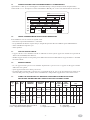
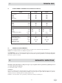
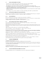
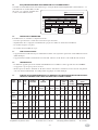
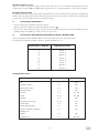
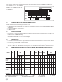
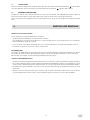
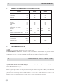
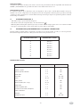
2.5 TABELLA II: DATI TECNICI GAS, PRESSIONE, UGELLI BRUCIATORE, PILOTA E VITE
DEL MINIMO. APPARECCHIO TIPO: GF49T E GF99T CON VASCHE DA 18 LITRI
•) Regolatore di pressione escluso Marcatura ugello Ø 1/100 mm. T.A. = Tutto aperto
(1) Compreso portata termica pilota circa 200 W. F = Fisso R = Regolabile
R.d.A. = Regolazione dell’aria primaria K = Ugello corto = 15 mm L = Ugello lungo = 25 mm
Nazione
e
Categoria
Cat.
Ugello
Tipo di
GAS
ITALIA
II2H3+
ITALIA
II2H3+
2H
3+
G20
METANO
G30
BUTANO
G31
PROPANO
PRESSIONE GAS
A MONTE mbar
Nom. Min. Max.
20
•) 29
•) 37
17
20
25
25
35
45
n° 3 BRUCIATORI
PER VASCA
Ø mm. Tipo
MARCATO
R.d.A.
X mm.
BY-PASS
Ø mm.
MARCATO
PILOTA
“targhet”
MARCATO
165/250 K
115/250 K
18
TA
28
-
-
36
19
Pressione
Gas ugello con
710min.
Max.
mbar
Min.
mbar
Portata
Termica Nom.
kW (1)
100% P.T.
Min.
Consumo Gas
(15°C)
l/h g/h
18,5
28,4
35,9
-
-
15
15
-
-
1588
465
613
-
1183
1166
l/h
3175
930
1227
GF49T GF99T
g/h
-
2366
2332
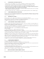
V Hz kW
Type
tipo
Mod.
Matr.N°
Cat.
P n
IT-GR-GB-ES-IE PT FR-BE NL
II2H3+ II2H3+ II2E+3+ II2L3P
20,29/37 20,29/37 20/25,29/37 25,30,50
Cat.
P n
LU IS-DK-FI-SE AT-CH DE NO
II2E3P II2H3B/P II2H3B/P II2ELL3B/P I3P
20,37,50 20,29 20,50 20,20,50 30
Qn
(Hi)
G20
G25
m
3
/h
m
3
/h
G30
G31
Kg/h
Kg/h
mbar
mbar
kW

- 6 -
I
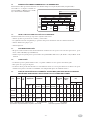
2.6 COLLEGAMENTO ALL’IMPIANTO DEL GAS
- L’apparecchio deve essere alimentato con gas avente le caratteristiche e la pressione riportata in tabella II.
- La pressione del gas si misura alla presa di pressione iniziale con i bruciatori accesi (vedere Fig. 1) e art. 2.7.
- L'apparecchiatura è collaudata e predisposta per funzionare col gas indicato sulla targhetta esterna adesiva.
* N.B. Se la pressione in rete varia più del +10% della pressione nominale, viene consigliato di montare un regolatore
di pressione a monte dell’apparecchio per garantire la pressione nominale.
- L’allacciamento alla rete del gas deve essere effettuato con tubazione metallica di adeguata sezione e deve essere inserito
a monte un rubinetto di intercettazione omologato.
- Dopo l’allacciamento alla rete del gas, controllare che non esistano perdite nei punti di raccordo con bolle di sapone.
2.6.1 SCARICO DEI PRODOTTI DI COMBUSTIONE
Gli apparecchi devono essere installati in locali adatti per lo scarico dei prodotti della combustione che deve avvenire nel
rispetto di quanto prescritto dalle norme d’installazione. Le nostre apparecchiature sono considerate (vedi Tabella 1.1 dati
tecnici) come apparecchi a gas tipo A
2.6.2 APPARECCHI A GAS TIPO: A
Non sono previsti per essere collegati ad un controllo di scarico dei prodotti della combustione.
L’apparecchiatura a gas va sistemata sotto una cappa di aspirazione il cui impianto deve avere le caratteristiche conformi alle
Norme. Questa apparecchiatura necessita di almeno 2 m
3
/h • kW P.T. (Portata Termica).
Controllare l’aerazione della cucina; deve essere secondo le norme in vigore.
2.6.3 COME OTTENERE LA PORTATA TERMICA NOMINALE
Controllare se l’apparecchio è predisposto per il tipo di gas, pressione e categoria che corrisponde con il gas disponibile in rete.
Indicazione riportata sull’imballo e/o targhetta sull’apparecchio.
Se l’apparecchio è predisposto per un altro tipo di gas e pressione, occorre prima fare una trasformazione per il funzionamento
ad altro tipo di gas. Vedere la Tabella II (art. 3.4.) per gli ugelli, vite del minimo (by-pass), regolazione dell’aria primaria, (X
mm), l’ugello del pilota e la pressione all’ugello del bruciatore principale.
N.B. I nomi degli ugelli «2H» e «3+» sono visibili nella parte sinistra della Tabella II.
2H = G 20 - 20 mbar
3 + = G 30 - 29 mbar e/o G 31 - 37 mbar una coppia di gas e pressione.
Nel nostro settore abbiamo quasi sempre a che fare con G 31 - 37 mbar!
Nella Tabella II sono riportati i tipi di gas e pressione per ogni bruciatore e il relativo ugello, la distanza X mm della
regolazione dell’aria primaria, la vite del minimo (by-pass), l’ugello del pilota, la pressione massima e minima all’ugello, la
portata termica massima e minima e il consumo gas in l/h (15°C) o in g/h in caso di G.P.L.
Attenzione: Se la pressione «dinamica» del gas a monte dell’apparecchio è inferiore alla pressione minima della Tabella II,
l’allacciamento è proibito; in più l’installatore deve comunicare all’azienda del gas che la pressione in rete è troppo bassa.
N.B.: Se la pressione varia più del +10% della pressione nominale p.e. per G 20 - 22 mbar viene consigliato di montare un
regolatore di pressione a monte dell’apparecchio per garantire la pressione nominale.
Se la pressione in rete è oltre la pressione massima della Tabella II p.e. per G 20 - 25 mbar avvertire l’azienda del gas.
Controllare se la pressione in entrata ed all’ugello corrisponde con i valori riportati nella Tabella II.
2.7 CONTROLLO DELLA PRESSIONE
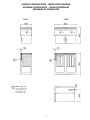
CONTROLLO DELLA PRESSIONE A MONTE (Pe) Fig. 1A
La pressione viene misurata con un manometro 0 ÷ 80 mbar (Precisione almeno 0,1 mbar).
La presa di pressione (B) si trova sulla rampa gas G 3/4" dietro il cruscotto; svitare la vite (A), attaccare la gomma al silicone al
manometro, accendere il bruciatore e rilevare la pressione «dinamica» a monte.
Rimontare la vite (A), controllare la tenuta gas con bolle di sapone.
CONTROLLO DELLA PRESSIONE ALL’UGELLO (Pi) Fig. 1A
La presa di pressione (B) si trova sopra il porta ugello (fig. 1B) svitare la vite (A) della presa di pressione (B), attaccare la
gomma al silicone nel manometro, accendere il bruciatore e rilevare la pressione all’ugello.
Rimontare la vite (A), controllare la tenuta gas con bolle di sapone.
2.8 REGOLAZIONE DELLA PORTATA TERMICA MINIMA
La portata termica minima non è registrabile poichè la valvola gas regola la piena potenza impostata.

- 7 -
I
2.9 CONTROLLO PER IL FUNZIONAMENTO A GAS LIQUIDO
Controllare se gli ugelli montati corrispondono con l’indicazione delle Tabelle II. Verificare se la pressione in entrata
corrisponde con le indicazioni delle Tabelle II. Controllare se l’impianto a gas G.P.L. ha due regolatori di pressione di
sufficiente capacità e se la capacità di evaporazione può essere considerata sufficiente. Vedere anche la pubblicazione
«Norme di installazione e caratteristiche di Impianti a gas G.P.L.».
2.9.1 CONTROLLO DEL FUNZIONAMENTO
- Mettere l’apparecchio in funzione secondo le istruzioni d’uso Cap. 5.
- Controllare che non ci siano delle perdite di gas secondo le normative locali.
- Controllare l’accensione e l’interaccensione del bruciatore pilota e bruciatore principale.
- Verificare lo scarico regolare dei gas della combustione.
- Incollare una targhettina adesiva “predisposizione gas” sulla targhetta della apparecchiatura per quale gas e pressione l’appa-
recchio è stato regolato.
2.10 INTRODUZIONE ALL’UTENTE
Spiegare il funzionamento e l’uso della friggitrice all’utente utilizzando il libretto istruzioni e illustrare eventuali cambiamen-
ti. Lasciare il libretto istruzioni in mano all’utente e spiegare che lo deve utilizzare per ulteriori consultazioni.
L’apparecchio deve essere controllato almeno ogni 6 mesi. Sono da controllare il gruppo bruciatore, l’accensione,
l’interaccensione, l’impostazione del massimo e del minimo.
Per l’eventuale riparazione rivolgersi solamente ad un centro di assistenza tecnica autorizzato e richiedere l’utilizzo di
ricambi originali. Prima di effettuare lo smontaggio dei componenti e la loro sostituzione chiudere il rubinetto del gas e
smontare il frontalino. Procedere ora alla sostituzione dei componenti più importanti:
A - Accenditore piezo elettrico
- Staccare il filo dell’alta tensione.
- Svitare il dado con una chiave di 27 mm.
- Sostituire l’accenditore.
- Rimontare il tutto seguendo l’ordine inverso di smontaggio.
3. TRASFORMAZIONE PER FUNZIONAMENTO AD ALTRO TIPO DI GAS
4. SOSTITUZIONE DEI COMPONENTI PIÙ IMPORTANTI
Chiudere il rubinetto del gas a monte dell’apparecchio.
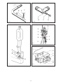
3.1 SOSTITUZIONE UGELLO BRUCIATORE PRINCIPALE ( FIG. 2)
- Aprire la porta armadio e togliere il contenitore dell’olio
- Allentare la vite (D) e spingere il regolatore dell’aria primaria (C) nel venturi
- Svitare con una chiave del 12 l’ugello (B) e sostituire con quello corrispondente al gas prescelto secondo quanto riportato
nella Tabella II.
3.2 REGOLAZIONE BRUCIATORE PILOTA (FIG. 3)
- Attenzione: Smontare per prima la candeletta (5) svitando il dado (8) con una chiave da 10 mm.
- Svitare il dado con una chiave da 10 mm. (2) e smontare l’ugello pilota ( 7) L’ugello è agganciato al bicono ( 3).
- Sostituire l’ugello pilota con quello corrispondente al gas prescelto secondo quanto riportato nella Tabella II.
- Stringere bene il dado con chiave da 10 mm.
IMPORTANTE: A conversione o adattamento per un tipo di gas, è obbligatorio attaccare la sigla corrispondente (adesivo in
dotazione insieme agli ugelli) sulla targhetta tecnica.
Terminata la sostituzione degli ugelli, applicare sopra alla targhetta esistente quella data in dotazione alla macchina
indicante il nuovo tipo di gas.

- 8 -
I
B - Candeletta del pilota “Targhet” Fig. 3 pos. 5
- Staccare il filo dell’alta tensione.
- Svitare il dado (Fig. 3 pos. 8) con una chiave di 10 mm.
- Sostituire la candeletta.
- Rimontare il tutto seguendo l’ordine inverso di smontaggio.
C - Termocoppia (Fig. 3 pos. 4)
- Svitare le due viti (Fig. 7 pos. 8) con una chiave di 8 mm.
- Svitare con una chiave di 9 mm, la termocoppia della valvola di sicurezza (Fig. 10).
- Rimontare il tutto seguendo l’ordine inverso di smontaggio.
D - Bruciatore pilota (Fig. 3)
- Smontare l’attacco gas, con una chiave di 10 mm (Fig. 3 pos. 2)
- Staccare il filo dell’alta tensione.
- Svitare le due viti di fissaggio
- Smontare la candeletta (Fig. 3 pos. 5) e la termocoppia (Fig. 3 pos. 4)
- Sosituire il corpo pilota (Fig. 3 pos. 6)
- Rimontare il tutto seguendo l’ordine inverso di smontaggio
ATTENZIONE: controllare la tenuta gas con bolle di sapone.
E - Valvola termostatica (Fig. 4)
- Estrarre il bulbo (Fig. 4 pos. L) dalla guaina.
- Staccare il tubo gas dalla uscita valvola.
- Smontare le 4 viti della flangia entrata gas.
ATTENZIONE: Controllare bene l’O.R. tenuta gas.
- Smontare la termocoppia con una chiave di 9 mm.
- Smontare il tubo gas alimentazione bruciatore pilota con una chiave di 10 mm.
- Sostituite la vecchia con una nuova valvola termostatica.
ATTENZIONE: I pulsanti debbono essere a sinistra, non dimenticate l’interruzione della termocoppia!
- Rimontare il tutto seguendo l’ordine inverso di smontaggio.
- Regolare la vite del minimo by-pass. (100% aperto!).
- Rimontare il bulbo della valvola e il bulbo del termostato limite (Fig. 3 pos. M).
ATTENZIONE: Controllare la tenuta del gas con bolle di sapone.
Controllare che la temperatura dell’olio arrivi a 195 °C con termostato in posizione 8.
F - Bruciatore (Fig. 2)
- Smontare il tubo alimentazione gas;
- Svitare le due viti con una chiave da 8 mm.
Ora si può sostituire il bruciatore (o i bruciatori).
- Rimontare il tutto seguendo l’ordine inverso di smontaggio.
ATTENZIONE: Controllare la tenuta gas con bolle di sapone.
G - Termostato di sicurezza
- Controllare il funzionamento e ricercare la causa che ha fatto scattare il termostato limite.
- La sua sostituzione è molto semplice.
ATTENZIONE: Il termostato interrompe il circuito della termocoppia.
Premessa
Prima di mettere in funzione l’apparecchiatura, lavare accuratamente la vasca ed i cestelli, operando come segue:
- Riempire la vasca fino a livello con acqua e detersivo, mettere in funzione il riscaldamento e portare in ebollizione per
alcuni minuti, scaricare l’acqua attraverso, il rubinetto di scarico e risciacquare abbondantemente la vasca con acqua pulita.
- Se per friggere si usa del grasso, non metterlo nella vasca se non è allo stato liquido; dopo l’uso scaricare il grasso
quando è ancora liquido.
- Quando si deve scaldare lo strutto solido, occorre farlo molto lentamente, forando spesso la superficie del grasso per
favorirne la dilatazione e lo scioglimento.
- Durante l’uso si raccomanda di non coprire la vasca o versare all’interno sali o aromi.
- Non mettere mai in funzione l’apparecchiatura prima di aver riempito d’olio il recipiente. La mancata avvertenza di tale
norma arrecherebbe gravi danni per il surriscaldamento nel fondo della vasca.
5. ISTRUZIONI PER L’UTENTE

- 9 -
I
RIEMPIMENTO VASCA
Assicurarsi che il rubinetto di scarico sia chiuso, quindi versare l’olio per friggere fino alla tacca MIN. e comunque non oltre
la tacca MAX. Per la capacità della vasca vedere la tabella dei dati tecnici 1.1.
RIEMPIMENTO DEL CESTELLO
La quantità di cibo da mettere nel cesto dipende da come si vuole cucinarla. Al momento dell’immersione nell’olio bisogna
evitare un rapido abbassamento della sua temperatura evitando comunque che scenda al di sotto dei 160 °C. Piccoli pezzi di
cibo cucinati per il giusto tempo, risultano comunque migliori di un grosso pezzo che deve essere cotto per più lungo tempo.
5.1 ACCENSIONE PILOTA (FIG. 4)
- Aprire il rubinetto del gas installato a monte dell’apparecchio.
- Girare la manopola della regolazione temperatura (R) portandola nella Posizione ( ).
- Premere e tenere premuto fino ad accensione avvenuta il pulsante pilota (N), contemporaneamente premere ripetutamente il
pulsante accensione e si accende il pilota. (L’accensione è verificabile con portine apparecchio aperto).
5.2 ACCENSIONE DEL BRUCIATORE PRINCIPALE E REGOLAZIONE DELLA TEMPERATURA
Dopo aver acceso il pilota, il bruciatore si accende girando la manopola (Fig. 4 pos. R), e portandola sulla posizione 8.
La regolazione della temperatura dell’olio avviene ruotando la manopola nelle posizioni da 1 a 8:
1
2
3
4
5
6
7
8
118 ± 8 °C
127 ± 8 °C
138 ± 8 °C
148 ± 8 °C
157 ± 8 °C
170 ± 8 °C
181 ± 8 °C
192 ± 8 °C
POSIZIONE MANOPOLA
TEMPERATURA OLIO
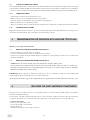
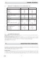
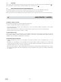
ESEMPI DI COTTURA
Cibo Tempo in minuti Termostato °C
Crostini
Gamberi e totani
Filetto di pesce impanato
Frittura mista
Salsicce
Polli
Polli novelli
Arrosti vari (da 1 a 2 kg)
Patatine e spicchi
Doratura di patate a spicchi
Fondi di carciofi, melanzane, cavolfiori, zucchini
Frittelle
Crocchette di riso
1
2 - 5
2 - 4
3 - 5
2 - 4
10 - 15
5 - 8
20 - 25
3 - 5
1 - 2
2 - 4
2 - 4
3 - 5
180
180
190
190
170 - 180
170 - 180
180
170
190
190
190
180
160 - 180

- 10 -
I
PULIZIA E ACCORGIMENTI
Per la pulizia attenersi alle seguenti istruzioni:
- Pulire il tutto senza usare lane metalliche o prodotti abrasivi.
- Si raccomanda che l’olio o il grasso che vengono usati per la cottura siano di buona qualità e sempre esenti da impurità;
queste debbono essere eliminate mediante filtrazione.
- Prima di versare l’olio fresco o filtrato nella vasca accertarsi che questa sia stata pulita a fondo.
- Mettere il coperchio all’apparecchio quando questo non viene usato.
VASCHE DI COTTURA
Svuotare le vasche dall’olio facendo scendere attraverso il rubinetto di scarico nella vasca raccogliolio collocata sotto
l’armadio, quindi pulire accuratamente usando un opportuno detergente ed evitando di raschiare o graffiare il fondo della
vasca stessa. Risciacquare abbondantemente in modo da togliere ogni traccia di detergente.
PARTI IN ACCIAIO INOSSIDABILE
- Pulire giornalmente la parti in acciaio inox con acqua tiepida saponata, quindi risciacquare abbondantemente ed asciugare
con cura.
- Evitare nel modo più assoluto di pulire l’acciaio inox con paglietta, spazzola o raschietti di acciaio comune in quanto
possono depositare particelle ferrose che ossidandosi provocano punti di ruggine. Può essere eventualmente adoperata
lana di acciaio inossidabile passata nel senso della satinatura.
- Qualora l’apparecchiatura non venga utilizzata per lunghi periodi, passare energicamente su tutte le superfici in acciaio un
panno appena imbevuto di olio di vaselina, in modo da stendere un velo protettivo. Arieggiare periodicamente i locali.
6. MANUTENZIONE E PULIZIA
5.3 SPEGNIMENTO
Lo spegnimento del bruciatore principale si ottiene girando la manopola (Fig. 4 pos. R) e portandola nella posizione
accensione pilota ( ). Per lo spegimento anche del pilota, premere il pulsante (Fig. 4 pos. S) contrassegnato con ( ) .
5.4 LIMITATORE DI TEMPERATURA
Le friggitrici sono dotate di un termostato di sicurezza che interviene in caso di surriscaldamento dell’olio.
Quando questo è intervenuto, per far ripartire l’apparecchio occorre riarmare il termostato.
Questa operazione deve essere effettuata da personale qualificato, che accerterà la causa del suo intervento.

- 11 -
GB
SECTION DESCRIPTION PAGE
General warnings ................................................................................................................................. 12
1. Technical data .................................................................................................................................... 13
1.1 Domina series gas fryer Cat. II (Natural gas and L.P.G) ....................................................................... 13
1.2 Technical characteristics ..................................................................................................................... 13
2. Installation instructions ..................................................................................................................... 13
2.1 Information on Domina series gas fryers ............................................................................................. 14
2.2 Laws, regulations and technical directives to be observed ................................................................ 14
2.3 Place of installation ............................................................................................................................. 14
2.4 Positioning .......................................................................................................................................... 14
2.5 Table II : gas technical data, pressure, burner nozzles, pilot and minimum screw.
Unit type: GF49T and GF99T with basin of 18 litres ......................................................................... 15
2.6 Hook-up with the gas system .............................................................................................................. 15
2.6.1 Discharging the products of combustion ............................................................................................ 15
2.6.2 Gas units type: A ................................................................................................................................. 15
2.6.3 How to obtain the nominal thermal capacity ...................................................................................... 15
2.7 Checking the pressure ......................................................................................................................... 16
2.8 Adjusting the minimum thermal capacity .......................................................................................... 16
2.9 Liquid gas operation check ................................................................................................................. 16
2.9.1 Operation check .................................................................................................................................. 16
2.10 Introduction to users ........................................................................................................................... 16
3. Transformation for operation with another type of gas.................................................................. 16
3.1 Replacing the main burner nozzle ...................................................................................................... 16
3.2 Adjusting the pilot burner ................................................................................................................... 16
4. Replacing the most important components ...................................................................................... 17
5. User instructions ................................................................................................................................. 18
5.1 Pilot ignition ....................................................................................................................................... 18
5.2 Main burner ignition and adjustment of the temperature ................................................................... 18
5.3 Switching off ....................................................................................................................................... 18
5.4 Cleaning and upkeep .......................................................................................................................... 18
5.5 Temperature limiting device ............................................................................................................... 19
6. Maintenance and cleaning ................................................................................................................. 19
INSTALLATION DIAGRAM ............................................................................................................... 47
CONTENTS

- 12 -
GB
In the event of the user or the installation technician failing to observe the instructions given in this manual, the Firm
disclaims all responsibility thereof and cannot be held liable for any accidents or trouble caused by such non-observance.
THE MANUFACTURER DISCLAIMS ALL RESPONSIBILITY FOR ANY INACCURACIES IN THIS BOOKLET THAT MAY BE
DUE TO TYPING OR PRINTING MISTAKES. THE MANUFACTURER, MOREOVER, RESERVES THE RIGHT TO MAKE THE
MODIFICATIONS TO THE PRODUCT IT CONSIDERS USEFUL OR NECESSARY, WITHOUT AFFECTING ITS BASIC FEATURES.
- Read the instructions contained in this manual carefully as they provide important information onsafe
installation, operation and maintenance procedures.
- Store this manual carefully for future reference by the operators.
- After removing the packing, check the integrity of the unit and, if in doubt, do not operate the unit, call professionally
qualified personnel.
- Before connecting the unit, make sure that the data on the plate correspond to those of the gas mains.
- This unit must only be used for the purposes for which it has been expressly designed, any other use is to be
considered improper and therefore dangerous.
- The unit must only be used by a specifically trained person.
- For any repairs, call solely a technical service centre authorized by the manufacturer and ask for genuine parts.
- Failure to comply with the above may jeopardize the safety of the unit.
- Never wash the unit with direct or high pressure jets of water.
- Do not obstruct air vents or heat dissipation openings.
GENERAL NOTICES

- 13 -
GB
1.1 DOMINA SERIES GAS FRYER CAT. II (NATURAL GAS AND L.P.G)
1.2 TECHNICAL CHARACTERISTICS
Frame made of AISI 304 stainless steel, panels and base of stainless steel, mounted on height-adjustable feet.
TANK made of AISI 304 stainless steel. With oil expansion area
GAS HEATING by means of self-adjusting flame burners made of cast iron, guaranteeing highly uniform heating. Thermostat
temperature control with safety valve and thermocouple to cut off the flow of gas if the pilot burner is accidentally extinguished.
Piezoelectric ignition of the pilot.
(1) Including the thermal capacity of the pilot burner approx. 400 W
MODEL
Tipo
mm
mm
mm
mm
kg.
mm
mm
mm
1
mm
mm
mm
ca. min.
°C/min.
“A”
(1) kW
m
3
/h
(15°C)
g/h
m
3
/h
m
3
/h
GF49T
A
450
900
580
680
-
1
290
400
300
18
13,2
11,8
G3/4”
16,5
24,8
1301-1282
1,75
2,1
12
260 120
310 310
130 130
GF99T
A
900
900
580
680
-
2
290
400
300
18 + 18
13,2
11,8
G3/4”
33
49,5
2602-2564
3,5
4,2
24
260 120
310 310
130 130
Dimensions
Width
Depth
Height
Total height
Net weight
Basin dimensions and No.
Width
Depth
Height
Basin capacity
Dimensions and No. of baskets
Width
Depth
Height
Pre-heating time (160 K)
Gas connection
Rated heat capacity
Air for combust. / ventil.
Gas consumption
L.P.G. G30/G31
Natural gas H-G 20
Natural gas L-G25
Installation and transformation for using other types of gas, if required, must be performed by qualified persons in
accordance with current regulations.
See technical data tables: 1.1 and 2.5
WARNINGS:
If the unit is installed against a wall, the wall needs to withstand temperatures of 100°C and must be fireproof, or be set at a
distance of 10 cm. Before proceeding with the installation, remove the protective plastic film and eliminate any adhesive
residues by means of a suitable product for cleaning stainless steel.
Install the oven horizontally, correct positioning is obtained by turning the levelling feet.
1. TECHNICAL DATA
2. INSTALLATION INSTRUCTIONS

- 14 -
GB
2.1 INFORMATION ON DOMINA SERIES GAS FRYERS
This booklet applies to our Domina series Fryers type A Category II (Natural Gas and L.P.G.). See table 1.1 - 2.5. The plate
according to EN 437 and EN 203 part 1
standards is under the bottom edge of the
instrument panel.
2.2 LAWS, REGULATIONS AND
TECHNICAL DIRECTIVES
TO BE OBSERVED
The following regulations must be observed
during installation:
- Current accident and fire regulations.
- The regulations of the gas supply
company, which has to issue an
authorization before installation.
- “Gas system installation” standards.
- Health regulations.
2.3 PLACE OF INSTALLATION
- The unit should be installed in a room with adequate ventilation. This unit requires a draft of at least 2 m
3
/h • kW T.C.
(Thermal Capacity).
- Install the unit in compliance with the safety regulations UNI - CIG 8723, Italian Law No. 46 dated 5-3-’90 and Ministerial
Decree No. 74 dated 12.04.96.
2.4 POSITIONING
- The various units may be installed separately or combined with other units in our range.
- This unit is not suitable for encasing.
- The distance from the side and rear walls must be at least 10 cm.; should the distance be less or the material of the walls or
floor be flammable, it is vital to install heat insulation.
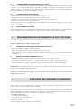
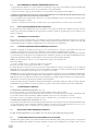
2.5 TABLE II: GAS TECHNICAL DATA, PRESSURE, BURNER NOZZLES, PILOT AND MINIMUM SCREW.
UNIT TYPE: GF49T AND GF99T WITH BASIN OF 18 LITRES
R.o.A. = Regulation of primary air (1) Including the pilot thermal capacity approx. 400W. Nozzle marking Ø 1/100
* Pressure regulator excluded K = Short nozzle l = 15 mm F = Fixed A = Adjustable TA = Open all
Nation
and
category
Cat.
NOZZLE
Type
of
gas
ENG, ICEL,
DENIM, FIN,
SWED, PORT,
GREECE,
IRELAND
NETHERLANDS
ICEL,
DENMARK,
FINLAND,
SWEDEND
IRELAND
PORTUGAL
ENGLAND
GREECE
NORWAY
LUXEMBURG
LUXEMBURG
NETHERLAND
2H
2L
3B/P
3+
3P
3P
3P
G20
G25
G30*
G31
G30*
G31
G31
G31
G31
Gas pressure
upstream
mbar
Nom. Min. Max.
20
25
29
29
37
30
37
50
17
20
25
20
25
20
25
42,5
25
30
35
35
45
35
45
57,5
Ø mm. Type
MARKED
R.d.A.
X mm.
BY-PASS
Ø mm.
MARKED
PILOT
“targhet”
MARKED
165/250 K
170/350 L
115/250 K
115/250 K
120 K
115/250 K
105/250 K
32
28
TA
TA
TA
TA
TA
-
-
-
-
-
-
-
36
36
19
19
19
19
19
Gas pressure at
nozzle
with 710
Max.
mbar
Min.
mbar
Nominal
Thermal
kW (1)
100% P.T.
Min.
Gas consumption
15°C
l/h g/h
18,5
23,2
28,4
28,4
36,9
29,3
36,8
49,2
-
-
-
-
-
-
-
15
15
15
15
15
15
15
-
-
-
-
-
-
-
1588
1846
465
408
465
613
613
613
613
-
-
1183
1022
1183
1116
1116
1116
1116
GF49T GF99T
l/h g/h
3175
3693
930
816
930
1227
1227
1227
1227
-
-
2366
2044
2366
2332
2332
2332
2332
N° 3 BURNERS
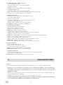
V Hz kW
Type
tipo
Mod.
Matr.N°
Cat.
P n
IT-GR-GB-ES-IE PT FR-BE NL
II2H3+ II2H3+ II2E+3+ II2L3P
20,29/37 20,29/37 20/25,29/37 25,30,50
Cat.
P n
LU IS-DK-FI-SE AT-CH DE NO
II2E3P II2H3B/P II2H3B/P II2ELL3B/P I3P
20,37,50 20,29 20,50 20,20,50 30
Qn
(Hi)
G20
G25
m
3
/h
m
3
/h
G30
G31
Kg/h
Kg/h
mbar
mbar
kW

- 15 -
GB
2.6 HOOK-UP WITH THE GAS SYSTEM
- The unit needs to be supplied with gas with the characteristics and pressure shown in Table II.
- The gas pressure is measured at the initial pressure test point with the burners on.
- The equipment is tested and preset in order to work with the gas indicated on the external adhestive plate.
* N.B. Should the supply pressure vary more than +10% of the nominal pressure, it is advisable to install a pressure
regulator upstream from the unit to guarantee the nominal pressure.
- Hooking up to the gas mains must be done with a metal pipe of suitable cross-section and a shut-off valve must be installed
upstream to standards.
- After hooking up to the gas mains, check there is no leakage at the fitting points with the soap solution method.
2.6.1 DISCHARGING THE PRODUCTS OF COMBUSTION
The units have to be installed in rooms suited to discharge the products of combustion that must take place in compliance
with the installation requirements. Our units are considered (see Table 1.1 technical data):
2.6.2 GAS UNITS TYPE: A
They are not fitted for being connected to an outlet check on the products of combustion.
The gas oven should be positioned under a suction hood whose system must have specifications in conformity with the
standards. This unit needs at least 2 m
3
/h • kW T.C. (Thermal Capacity).
Check the ventilation in the kitchen. It must be in accordance with current standards.
2.6.3 HOW TO OBTAIN THE NOMINAL THERMAL CAPACITY
Check whether the unit is fitted for the gas type, pressure and category corresponding to the main gas supply.
Information shown on the packing and/or unit label.
If the unit is fitted for another type of gas or pressure, you first need to transform it for working with the other kind of gas. See
Table II for the nozzles, minimum screw (by-pass), primary air adjustment, (X mm), pilot nozzle and nozzle pressure for the
main burner.
N.B.: The names of nozzles ”2H” and ”3+” are shown on the left side of Table II.
2H = G 20 - 20 mbar 3 + = G 30 - 29 mbar and/or G 31 - 37 mbar coupled gas and pressure.
In our sector we nearly always have to deal with G 31 - 37 mbar!
Table II shows the types of gas and pressure for all burners and their nozzles, the distance X mm of the primary air adjustment,
the minimum screw (by-pass), the pilot nozzle, the maximum and minimum nozzle pressure, the maximum and minimum
thermal capacity and the gas consumption in l/h (15°C) or in g/h in the case of L.P.G.
Caution: If the ”dynamic” pressure of the gas upstream from the unit is lower than the minimum pressure of Table II,
connection is prohibited; furthermore, the fitter must notify the gas company that the supply pressure is too low.
N.B.: Should the pressure vary by more than +10% of the nominal pressure, e.g. for G 20 • 22 mbar it is advisable to install a
pressure regulator upstream from the unit to guarantee the nominal pressure.
Should the supply pressure exceed the maximum pressure of Table II, e.g. for G 20 • 25 mbar, notify the gas company.
Check whether the incoming and nozzle pressures correspond to the values given in Table II.
2.7 CHECKING THE PRESSURE
INCOMING PRESSURE CHECK (Pe) Fig. 1A
The pressure is measured with a pressure gauge 0 ÷ 80 mbars (precision at least 0.1 mbars).
The pressure test point (B) is on the gas ramp behind the instrument panel; undo the screw (A), attach the silicone rubber hose
to the pressure gauge, ignite the burner and note the incoming ”dynamic” pressure. Fasten the screw (A) back on, check there
is no leakage with the soap solution method.
NOZZLE PRESSURE CHECK (Pi) Fig. 1B
The pressure test point (B) is over the nozzle holder; undo the screw (A) of the pressure test point (B), attach the silicone
rubber hose to the pressure gauge, ignite the burner and note the nozzle pressure.
2.8 ADJUSTING THE MINIMUM THERMAL CAPACITY
The minimum thermal capacity is not adjustable because the gas valve adjusts only the set full power.

- 16 -
GB
2.9 LIQUID GAS OPERATION CHECK
Check whether the fitted nozzles correspond to the information of Tables II. Check whether the incoming pressure corresponds
to the information of Tables II. Make sure that the L.P.G. system has two pressure regulators of sufficient capacity and that the
evaporation capacity is sufficient. See also the publication entitled ”Installation Instructions and Specifications of LPG systems.”.
2.9.1 OPERATION CHECK
- Start the unit according to the user instructions, Sect. 5.
- Make sure there are no gas leaks following the local procedures.
- Check the ignition and inter-ignition of the pilot burner and main burner.
- Make sure the flue gases are discharged properly.
- Write on a ”gas fitting” sticker, to stick onto the unit data plate, the gas and pressure for which the unit has been calibrated.
2.10 INTRODUCTION TO USERS
Explain the operation and use of the fryer to the user by referring to the instructions booklet and illustrate any changes. Leave
the instructions booklet with the user and explain he needs it for further reference.
3. TRANSFORMATION FOR OPERATION WITH ANOTHER TYPE OF GAS
The unit needs to be checked at least once every 6 months. You have to check the burner assembly, ignition, inter-ignition,
maximum and minimum settings.
For any repairs, call solely an authorized technical service centre and ask for genuine parts. Before removing and replacing
components, shut off the gas cock and take off the front panel. Now go ahead and replace the most important parts:
A - Piezoelectric ignition
- Disconnect the high-voltage cable.
- Unscrew the nut with a 27 mm wrench.
- Replace the igniter.
- Fit it all back together in reverse order to the above.
4. REPLACING THE MOST IMPORTANT COMPONENTS
Shut the gas valve upstream from the unit.
3.1 REPLACING THE MAIN BURNER NOZZLE ( FIG. 2)
- Open the cabinet door and remove the oil containers
- Loosen screw (D) and press the primary air regulator (C) in the venturi
- Using a size 12 spanner, unscrew nozzle (B) and replace it with the one corresponding to the selected gas, according to the
indication on Table II
3.2 REPLACING THE PILOT BURNER NOZZLE (FIG. 3)
- Attention: first remove the spark-plug (5) by unscrewing the nut ( 8) with a 10 mm. spanner.
- Unscrew the nut using a 10 mm. spanner (2) and remove the pilot nozzle (7) The nozzle is hooked on to the bicone (3)
- Exchange the pilot nozzle with one corresponding with the selected gas, in accordance with the indication of Table II
- Tighten the nut firmily with a 10 mm. spanner.
IMPORTANT: When converting or adapting to another type of gas, it is compulsory to affix the corresponding initials
(sticker supplied together with nozzles) on to the technical data plate.
After replacing the nozzles, apply on the existing label the one supplied with the machine indicating the new type of gas.

- 17 -
GB
B - Pilot spark-plug “Targhet” (fig. 3 pos. 5)
- Detach the high-voltage wire
- Unscrew the nut (fig. 3 pos. 8) using a 10 mm. spanner
- Replace the spark-plug
- Mount everything back by following the reverse order sequence
C - Thermocouple (Fig. 3 pos. 4)
- Undo the two screws (Fig. 7 pos. 8) with an 8mm wrench.
- Using a 9mm wrench, unscrew the thermocouple (Fig. 10).
- Fit it all back together in reverse order to the above.
D - Pilot burner (Fig. 3 )
- Remove the gas connection with a 10mm wrench (Fig. 3 pos. 2)
- Disconnect the high-voltage cable.
- Undo the two screws
- Remove the spark plug (Fig. 3 pos. 5) and the thermocouple (Fig. 3 pos. 4)
- Replace the pilot body (Fig. 3 pos. 6)
- Fit it all back together in reverse order to the above.
CAUTION: Check there is no gas leakage with the soap solution method.
E - Thermostat (Fig. 4)
- Take out the bulb (Fig. 4 pos. L) from the sheath.
- Disconnect the gas pipe from the valve outlet.
- Remove the 4 screws of the flange of the gas inlet.
CAUTION: Check the gas O-ring properly.
- Remove the thermocouple with a 9 mm wrench.
- Remove the pilot burner gas supply pipe with a 10mm wrench.
- Replace the old thermostat with a new one.
CAUTION: The push-buttons need to be on the left, don’t forget the thermocouple break!
- Fit it all back together in reverse order to the above.
- Adjust the by-pass minimum screw (100% open!).
- Fit the valve bulb and the limiting thermostat bulb (Fig. 3 pos. M).
CAUTION: Check there is no gas leakage with the soap solution method.
Check that the oil temperature reaches 195°C with the thermostat on position 8.
F - Burner (Fig. 2)
- Remove the gas supply pipe).
- Undo the two screws with an 8mm wrench.
- Now you can replace the burner (or burners).
- Fit it all back together in reverse order to the above.
CAUTION: Check there is no gas leakage with the soap solution method.
G - Safety thermostat
- Check its operation and look for the cause that made the limiting thermostat trip.
- It is extremely simple to replace.
CAUTION: The thermostat interrupts the thermocouple circuit.
Preliminary note
Before starting the unit, wash the inside of the basin and the baskets, proceeding as follows:
- Fill the basin up to its level with water and detergent, start heating and bring to the boil for a few minutes. Drain off the water
through the drain cock and rinse the basin thoroughly with clean water.
- If you use grease for frying, do not put it into the basin unless it is liquid; after use, drain off the grease while it is still liquid.
- When you need to heat solid lard, you need to do it extremely slowly, perforating the surface of the grease often to help it
expand and melt.
- During use, it is recommended not to cover the basin or pour salt or flavouring inside.
- Never start the unit without first filling the container with water. Failure to observe this instruction would cause severe
damage due to the bottom of the basin overheating.
5. USER INSTRUCTIONS

- 18 -
GB
FILLING THE BASIN
Make sure the drain cock is closed, then pour the frying oil in up to the MIN. mark and anyhow not over the MAX. mark. For
the capacity of the basin see the technical data table 1.1.
FILLING THE BASKET
The amount of food to put into the basket depends on how you want to cook it. When dipping it into the oil you need to
prevent a sharp drop in its temperature, anyhow not letting it fall under 160°C. Small pieces of food cooked for the right
length of time are anyhow better than one large piece that needs to be cooked longer.
5.1 PILOT IGNITION (FIG. 4)
- Open the gas cock installed upstream from the unit.
- Turn the temperature adjustment knob (R) onto ( ).
- Press and hold down the pilot push-button (N) until ignition, while repeatedly pressing the ignition push-button and the
pilot lights up. (Ignition can be checked with the unit doors open).
5.2 MAIN BURNER IGNITION AND ADJUSTMENT OF THE TEMPERATURE
After igniting the pilot, the burner is ignited by turning the knob (Fig. 4 pos. R) onto position 8.
The oil temperature is adjusted by turning the knob onto the positions from 1 to 8:
1
2
3
4
5
6
7
8
118 ± 8 °C
127 ± 8 °C
138 ± 8 °C
148 ± 8 °C
157 ± 8 °C
170 ± 8 °C
181 ± 8 °C
192 ± 8 °C
KNOBPOSITION
OIL TEMPERATURE
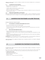
Food Temi in minutes Termostato °C
1
2 - 5
2 - 4
3 - 5
2 - 4
10 - 15
5 - 8
20 - 25
3 - 5
1 - 2
2 - 4
2 - 4
3 - 5
180
180
190
190
170 - 180
170 - 180
180
170
190
190
190
180
160 - 180
Croutons
Prawns and squid
Breaded fish fillet
Mixed fry
Sausages
Chicken
Spring chicken
Roasts (from 1 to 2 kg)
French fries
Browning French fries
Bottoms of artichokes, aubergines,
cauliflowers, courgettes
Fritters
Rice croquettes
EXAMPLES OF COOKING

- 19 -
GB
5.3 SWITCHING OFF
The main burner is turned off by turning the knob (Fig. 4 pos. R) onto pilot ignition ( ). To turn off the pilot as well, press
the push-button (Fig. 4 pos. S) marked with (
) .
5.4 TEMPERATURE LIMITING DEVICE
The fryers are equipped with a safety thermostat that trips if the oil overheats.
When it has tripped, in order to restart the unit you need to reset the thermostat .
This must be done by trained personnel who will ascertain the reason for it tripping.
CLEANING AND UPKEEP
Keep to the following cleaning instructions:
- Clean it all without using steel wool or any abrasive products.
- The oil or grease used for cooking must be of good quality and free of impurities, which have to be removed by filtration.
- Before pouring fresh or filtered oil into the basin, check it has been thoroughly cleaned.
- Put the lid on the appliance when it is not used.
COOKING BASINS
Drain the oil from basins by making it flow down through the drain cock into the oil tank under the cabinet. Then clean it
carefully using an appropriate detergent without scraping or scratching the bottom of the basin. Rinse thoroughly so as to
eliminate every trace of detergent.
STAINLESS STEEL PARTS
- Clean the stainless steel parts every day with warm soapy water, then rinse thoroughly and dry carefully.
- You must never clean the stainless steel with steel wool, wire brushes or common steel scrapers since they may deposit
ferrous particles that on oxidizing cause rust points. Stainless steel wool may be used applied in the direction of the satin
finish.
- If the unit is not to be used for a long time, give all the steel surfaces a good wipe over with a cloth lightly soaked in Vaseline
oil in order to apply a protective film. Periodically ventilate the premises.
6. MAINTENANCE AND CLEANING

- 20 -
F
CHAPITRE DESCRIPTION PAGE
Règles générales .................................................................................................................................. 21
1. Données techniques ............................................................................................................................ 22
1.1 Friteuses au gaz serie domina Cat. II (Gaz methane et G.P.L.) ............................................................ 22
1.2 Caracteristiques techniques ................................................................................................................ 22
2. Instructions pour l’installation ......................................................................................................... 22
2.1 Plaquette d’identification friteuses au gaz serie Domina ................................................................... 23
2.2 Legislation a respecter ........................................................................................................................ 23
2.3 Lieu d’installation ............................................................................................................................... 23
2.4 Mise en place ....................................................................................................................................... 23
2.5 Tableau II: Donnees techniques gaz, pression, gicleurs bruleurs, pilote et vis du minimum.
Appareil type: GF49T et GF99T avec cuve de 18 litres ..................................................................... 23
2.6 Raccordement au reseaux de distribution du gaz ...............................................................................24
2.6.1 Evacuation des produits de combustion ............................................................................................. 24
2.6.2 Appareils au gaz de type A ................................................................................................................. 24
2.6.3 Comment obtenir le debit thermique nominal.................................................................................... 24
2.7 Controle de la pression........................................................................................................................ 24
2.8 Reglage du debit thermique minimum ............................................................................................... 24
2.9 Controle pour le fonctionnement au gaz liquide ................................................................................ 24
2.9.1 Controle du fonctionnement ............................................................................................................... 25
2.10 Informations destinees a l’utilisateur .................................................................................................. 25
3. Adaptation pour fonctionner a un autre type de gaz ....................................................................... 25
3.1 Changement du gicleur du bruleur principal ...................................................................................... 25
3.2 Reglage du bruleur pilote ................................................................................................................... 25
4. Changement des composants plus importants ................................................................................. 25
5. Mode d’emploi.................................................................................................................................... 26
5.1 Allumage du pilote .............................................................................................................................. 27
5.2 Allumage du bruleur principal et reglage de la temperature .............................................................. 27
5.3 Extinction............................................................................................................................................ 27
5.4 Conseil d’utilisation ........................................................................................................................... 27
5.5 Temperature de securite ....................................................................................................................... 28
6. Entretien & nettoyage........................................................................................................................ 28
SCHEMAS D’INSTALLATION ........................................................................................................... 47
SOMMAIRE
Seite laden ...
Seite laden ...
Seite laden ...
Seite laden ...
Seite laden ...
Seite laden ...
Seite laden ...
Seite laden ...
Seite laden ...
Seite laden ...
Seite laden ...
Seite laden ...
Seite laden ...
Seite laden ...
Seite laden ...
Seite laden ...
Seite laden ...
Seite laden ...
Seite laden ...
Seite laden ...
Seite laden ...
Seite laden ...
Seite laden ...
Seite laden ...
Seite laden ...
Seite laden ...
Seite laden ...
Seite laden ...
Seite laden ...
-
 1
1
-
 2
2
-
 3
3
-
 4
4
-
 5
5
-
 6
6
-
 7
7
-
 8
8
-
 9
9
-
 10
10
-
 11
11
-
 12
12
-
 13
13
-
 14
14
-
 15
15
-
 16
16
-
 17
17
-
 18
18
-
 19
19
-
 20
20
-
 21
21
-
 22
22
-
 23
23
-
 24
24
-
 25
25
-
 26
26
-
 27
27
-
 28
28
-
 29
29
-
 30
30
-
 31
31
-
 32
32
-
 33
33
-
 34
34
-
 35
35
-
 36
36
-
 37
37
-
 38
38
-
 39
39
-
 40
40
-
 41
41
-
 42
42
-
 43
43
-
 44
44
-
 45
45
-
 46
46
-
 47
47
-
 48
48
-
 49
49


MBM GF49T Installation, Use And Maintenance Instructions
- Typ
- Installation, Use And Maintenance Instructions
- Dieses Handbuch ist auch geeignet für
Sonstige Unterlagen
-
Hobart G6SFA77 Installation, Use And Maintenance Instructions
-
Bartscher PM8-9IE Benutzerhandbuch
-
Evolve E80CBG04 Instruction, Use And Maintenance Manual
-
Hendi 225899 Benutzerhandbuch
-
Groupe Brandt DTG1038X Bedienungsanleitung
-
Electrolux FGH50K1-4.2 Benutzerhandbuch
-
-
Whirlpool AGB 626/WP Bedienungsanleitung
-
Caterchef 508124 Benutzerhandbuch
-
 STILFER 527009 Benutzerhandbuch
