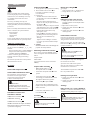
Danfoss AHQM, AHPBM-F Bedienungsanleitung
- Typ
- Bedienungsanleitung

Instructions
AHQM, AHPBM-F – PN 10 / DN 20-32
73695230 DH-SMT/SI VI.LR.B1.02 © Danfoss 11/2007 1
DN 20 DN 25 - 32
p = 0.12 p = 0.14
ENGLISH
Flow controller / diff. pressure controller with flow limitation,
with integrated control valve AHQM, AHPBM-F
www.danfoss.com Page 5
DEUTSCH
Durchfluss/Differenzdruckregler AHQM, AHPBM-F mit
Volumenstrombegrenzung,
www.danfoss.de Seite 7

11
DN 20 25 32
SW
mm
41 (G 1A) 50 (G 1¼A) 63 (G 1¾A)
d 26 33 42
R
1)
¾ 1 1 ¼
L1
2)
150 160 -
L2 144 160 177
L3 154 159 184
k 75 85 100
d
2
14 14 18
n 4 4 4
1)
EN 10226-1
2)
EN 1092-2
AMV(E) 10 + AH...
AMV(E) 13 + AH...
DN 20 25 32
L
mm
82 104 130
L*
AMV(E) 150 132 148 167
AMV(E) 10 137 153 172
AMV(E) 13 147 164 183
L* *
AMV(E) 150 160 178 198
AMV(E) 10 186 204 224
AMV(E) 13 196 214 234
H 31 39 49
H1 59 72 84
H*
AMV(E) 150 184 206 226
AMV(E) 10 201 223 245
AMV(E) 13 216 238 260
H**
AMV(E) 150 178 196 216
AMV(E) 10 184 202 222
AMV(E) 13 190 208 228
D (ISO 228/1) G 1 A G 1¼ A G 1¾ A
Valve weight kg 0.67 1.47 2.23
AMV(E) 150 + AH...
Nipples
73695230 DH-SMT/SI VI.LR.B1.02 © Danfoss 11/2007 2

109
8
1
2
4
5
3
D N L (mm)
15 69
20 74
25 79
32 104
L
6
7
G /
G /
AMV AME
73695230 DH-SMT/SI VI.LR.B1.02 © Danfoss 11/2007 3

M
12
∆p
v
13
14
–
+
M
15
16
1 = 360°
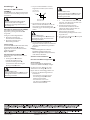
DN 32 k
vs
6.3DN 25 k
vs
4.0DN 20 k
vs
2.5
73695230 DH-SMT/SI VI.LR.B1.02 © Danfoss 11/2007 4

73695230 DH-SMT/SI VI.LR.B1.02 © Danfoss 11/2007 5
DANSKENGLISH
Safety Notes
Prior to assembly and commissioning
to avoid injury of persons and damages
of the devices, it is absolutely necessary
to carefully read and observe these
instructions.
Necessary assembly, start-up, and
maintenance work must be performed
only by qualified, trained and authorized
personnel.
Prior to assembly and maintenance work
on the controller, the system must be:
- depressurized,
- cooled down,
- emptied and
- cleaned.
Please comply with the instructions of the
system manufacturer or system operator.
Definition of Application
The controller is in combination with
electrical actuators (AMV(E) 1_,2_, 3_, 150)
used for:
- flow and temperature control (AHQM) or
- diff. pressure and temperature control
with flow limitation (AHPBM-F)
in water and water glycol mixtures for
heating, district heating and cooling
systems.
The technical parameters on the product
labels determine the use.
Assembly
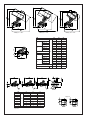
Admissible Temperatures
1
Admissible Installation Positions
2
The controllers can be installed in
horizontal or vertical pipes with
(connection neck for) electrical
actuator oriented upwards.
Electrical actuator
Installation positions for electrical
actuator AMV(E) have to be observed as
well. Please see relevant Instructions.
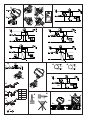
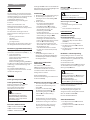
Installation Location and
Installation Scheme
AHQM return mounting
4
AHQM flow mounting
5
AHPBM-F flow mounting
3
AHPBM-F controller can only be installed in
flow pipeline in direct-connected heating
system with mixing loop.
Valve Installation
6
1. Clean pipeline system prior to assembly.
2. The installation of a strainer
in
front of the controller is strongly
recommended.
3. Install valve
• The ow direction indicated on the
product label or on the valve
must
be observed.
• The valve with mounted weld-on
tailpieces may only be spot welded to
the pipeline
.
The weld-on tailpieces may be welded
only without the valve and seals!
If these instructions are not observed,
high welding temperatures may
destroy the seals.
• Flanges
in the pipeline must be in
parallel position and sealing surfaces
must be clean and without any
damage.
Tighten screws in flanges crosswise
in 3 steps up to the maximum torque
(50 Nm).
4. Caution:
Mechanical loads of the valve body by the
pipelines are not permitted.
Mounting of electrical actuator
7
Place electrical actuator AMV(E) on the
valve and tighten union nut with wrench
SW 32.
Torque 25 Nm.
Other details:
See instructions for electrical actuator
AMV(E).
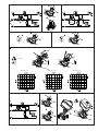
Impulse tube mounting
8
• Which impulse tubes to use?
Use impulse tube set AH
• Connection of impulse tube in the
system
• Connection to the pipeline
9
It is strongly recommended to install
the impulse tube to the pipeline
horizontally
or upwards .
This prevents dirt accumulation in the
impulse tube and possible malfunction
of the controller.
Connection downwards is not
recommended
.
Insulation
10
The controller may also be insulated.
Insulation of electrical actuator
AMV(E) is not allowed.
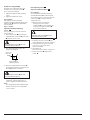
Dimensions, Weights
11
(See page 2)
1)
Conical ext. thread acc. to EN 10226-1
2)
Flanges PN 25, acc. to EN 1092-2
Start-up
12
Filling the system, first start-up
1. Slowly open shut-off valves that are
possibly available on the impulse tube
(AHPBM-F).
2. Open valves in the system.
3. Slowly open shut-off devices
in the
flow pipeline.
4. Slowly open shut-off devices
in the
return pipeline.
Leak and Pressure Tests
Pressure tests should be carried out prior
to the installation of the electrical actuator.
This guarantees that the valve is opened.
Before pressure test, open the adjustable
flow restrictor
by turning it to the left
(counter clockwise).
Adjustable flow restrictor has to be
moved by hand not by tool.
Pressure must be gradually increased at
the (+/-) connection
.
Non-compliance may cause damages at
the actuator or the valve.
A pressure test of the entire system
must be carried out in accordance with
manufacturer’s instructions.
The maximum test pressure is: 1.5 × PN
PN - see product label!
Putting out of operation
1. Slowly close shut-off devices in the
flow pipeline.
2. Slowly close shut-off devices
in the
return pipeline.
Settings
Differential Pressure Setting (AHPBM-F)
AHPBM-F is controller with fixed p setting.
Therefore setting of p is not required.
If the required differential pressure is not
attained, a cause may be a too small
pressure loss in the system.

73695230 DH-SMT/SI VI.LR.B1.02 © Danfoss 11/2007 6
Flow Rate Setting (AHQM)
The flow rate is adjusted by means of
limitation of control valve stroke
.
There are two possibilities:
1. Adjustment with the flow adjusting
curves,
2. Adjustment with heat meter.
Pre-condition
(Min. diff. pressure over the valve)
To achieve maximum flow rate the pressure
difference Δp
v
across the control valve
must be at least:
∆p
min
= 0.5 bar
Adjustment with flow adjusting
curves
13
The system don’t need to be active for
being adjusted.
1. Close control valve
by turning the
adjustable flow restrictor
to the right
(clockwise) to its stop.
Adjustable flow restrictor has to be
moved by hand not by tool.
2. Select flow adjusting curve in the
diagram (see page 4).
No
Necessary
flow rate
Revolutions of
adjusting throttle
3. Open the adjustable flow restrictor
by determined number of revolutions to
the left
(counter clockwise):
Adjustable flow restrictor has to be
moved by hand not by tool.
4. The setting of the valve stroke is
completed, continue with step 2 in
section Adjustment with Heat Meter.
Note:
The setting may be verified with help of a
heat meter if the system is in operation,
see next section.
Flow Adjusting Curves
14
Adjustment with Heat Meter
15
Pre-condition:
The setting can be carried out when the
electrical actuator AMV(E) is dismounted.
The system must be in operation. All units
in the system
or a bypass must be
completely open.
1. Observe heat meter indicator:
- turning to the left (counter
clockwise)
increases the flow rate
- turning to the right (clockwise)
decreases the flow rate
Adjustable flow restrictor has to be
moved by hand not by tool.
After the adjustment has been completed
16
:
2. Install the electrical actuator
, see
section Mounting of electrical actuator.
3. Shortly throttle the system and then
re-open it (e.g. by means of the
electrical actuator).
4. Verify flow rate.
The control valve setting is completed.
5. Electrical actuator
may now be
sealed
.

73695230 DH-SMT/SI VI.LR.B1.02 © Danfoss 11/2007 7
Sicherheitshinweise
Vor dem Einbau und der Inbetriebnahme
ist zur Vermeidung von Personenschäden
und Beschädigungen an Anlagenbauteilen
die vorliegende Betriebsanleitung
sorgfältig durchzulesen. Die
Betriebsanleitung ist unbedingt zu
beachten.
Einbau-, Inbetriebnahme- und
Wartungsarbeiten dürfen nur durch
geschultes und autorisiertes Fachpersonal
durchgeführt werden.
Vor dem Einbau des Reglers und vor
Wartungsarbeiten am Regler muss die
Anlage:
- drucklos gemacht werden
- abkühlen
- entleert werden
- gereinigt werden.
Die Vorgaben des Anlagenherstellers und
des Anlagenbetreibers sind zu beachten.
Bestimmungsgemäße Verwendung
Der Regler wird in Verbindung mit
elektrischen Stellantrieben (AMV(E) 1_, 2_,
3_, 150) eingesetzt zur
- Volumenstrom- und
Temperaturregelung (AHQM) oder
- Differenzdruck- und
Temperaturregelung mit
Volumenstrombegrenzung (AHPBM-F)
von Wasser und Wasser-Glycol-Gemischen
in Heizungs-, Fernwärmeheizungs- und
Kühlanlagen.
Die auf den Produktaufklebern
angegebenen technischen Daten sind für
den Einsatz maßgebend.
Montage
Zulässige Temperaturen
1
Zulässige Einbaulagen
2
Einbau in horizontale oder vertikale
Rohrleitungen mit nach oben
zeigendem (Anschlussstutzen
für) elektrischen Stellantrieb.
Elektrischer Stellantrieb
Die Einbaulagen des elektrischen
Stellantriebs AMV(E) sind ebenfalls
zu beachten. Siehe entsprechende
Betriebsanleitungen.
Einbauort, Einbauschema
AHQM – Einbau im Rücklauf
4
AHQM – Einbau im Vorlauf
5
AHPBM-F – Einbau im Vorlauf
3
Der Regler AHPBM-F kann nur im Vorlauf von
direkt angeschlossenen Heizungsanlagen mit
Mischkreis eingebaut werden.
Ventileinbau
6
1. Rohrleitungen vor dem Einbau reinigen.
2. Es wird dringend empfohlen, vor
dem Regler einen Schmutzfänger
einzubauen.
3. Ventil einbauen
• Die auf dem Produktaufkleber
oder dem Ventil angegebene
Durchflussrichtung
beachten.
• Das Ventil mit den angeschraubten
Anschweißenden nur an die
Rohrleitung anheften
.
Das Einschweißen der
Anschweißenden darf nur ohne Ventil
und Dichtungen erfolgen!
Bei Nichtbeachtung werden die
Dichtungen des Ventils durch die
hohen Schweißtemperaturen zerstört.
• Flansche
in der Rohrleitung
müssen parallel ausgerichtet und
die Dichtflächen sauber und frei von
Beschädigungen sein.
Schrauben über Kreuz in 3 Stufen
bis zum max. Drehmoment (50 Nm)
anziehen.
4. Achtung:
Ventil spannungsfrei einbauen. Es
dürfen keine mechanischen Kräfte über
die Rohrleitungen auf den Ventilkörper
übertragen werden.
Anbau eines elektrischen
Stellantriebs
7
Den elektrischen Stellantrieb
AMV(E) auf dem Ventil aufsetzen
und die Überwurfmutter mit einem
Schraubenschlüssel SW 32 festziehen.
Anzugsmoment: 25 Nm.
Weitere Informationen:
Siehe Betriebsanleitung vom elektrischen
Stellantrieb AMV(E).
Montieren der Steuerleitung
8
• Das Steuerleitungsset AH
verwenden.
• Anschluss der Steuerleitung in der
Anlage
.
• Anschluss an die Rohrleitung
9
Es wird dringend empfohlen, die
Steuerleitung waagerecht
oder
aufrecht
an die Rohrleitung
anzuschließen.
Dadurch werden ein Verschmutzen
der Steuerleitung und eine mögliche
Fehlfunktion des Reglers verhindert.
Die Steuerleitung sollte nicht nach
unten zeigend an die Rohrleitung
angeschlossen werden
.
Dämmung
10
Der Differenzdruckregler kann mit
isoliert werden.
Das Dämmen des elektrischen
Stellantriebs AMV(E) ist nicht zulässig.
Abmessungen, Gewichte
11
(siehe Seite 2)
1)
Kegeliges Außengewinde nach EN
10226-1
2)
Flansche PN 25 nach EN 1092-2
Inbetriebnahme
12
Auffüllen der Anlage,
Erstinbetriebnahme
1. Eventuell in den Steuerleitungen
vorhandene Absperrventile öffnen
(AHPBM-F).
2. Die Ventile in der Anlage öffnen.
3. Die Absperrarmaturen
im Vorlauf
langsam öffnen.
4. Die Absperrarmaturen
im Rücklauf
langsam öffnen.
Dichtheits- und Druckprüfung
Druckprüfungen sollten vor Anbau des
elektrischen Stellantriebs durchgeführt
werden. Dadurch ist gewährleistet, dass
das Ventil geöffnet ist.
Vor dem Drucktest den
Volumenstrombegrenzer
durch Drehen
der Einstelldrossel nach links (gegen den
Uhrzeigersinn)
öffnen.
Die Einstelldrossel des
Volumenstrombegrenzers
darf nur von
Hand gedreht werden. Zum Drehen kein
Werkzeug verwenden.
Die Druckerhöhung am (+/-)-
Anschluss
muss gleichmäßig erfolgen.
Nichtbeachtung kann zu Schäden am
Antrieb oder Ventil führen.
Die Druckprüfung der Anlage muss
unter Beachtung der Vorgaben des
Anlagenherstellers durchgeführt werden.
Max. zul. Prüfdruck: 1.5 × PN
PN siehe Produktaufkleberl!
Außerbetriebnahme
1. Die Absperrarmaturen im Vorlauf
langsam schließen.
2. Die Absperrarmaturen
im Rücklauf
langsam schließen.
DEUTSCH

11
73695230 DH-SMT/SI VI.LR.B1.02 © Danfoss 11/2007 8
Einstellungen
Einstellen des Differenzdrucks
(AHPBM-F)
Der AHPBM-F ist ein Regler mit festem ∆p.
Deshalb ist eine Einstellung von ∆p nicht
erforderlich.
Wird der erforderliche Differenzdruck
nicht erreicht, kann eine mögliche
Ursache ein zu geringer Druckverlust in
der Anlage sein.
Einstellen des Volumenstroms (AHQM)
Der Volumenstrom wird durch die
Begrenzung des Regelventilhubs
eingestellt.
Dazu gibt es zwei Möglichkeiten:
1. Einstellung mit Hilfe von
Volumenstromeinstellkurven.
2. Einstellung mit Hilfe eines
Wärmemengenzählers.
Voraussetzung
(Erf. Mindestdifferenzdruck über dem Ventil)
Die Druckdifferenz Δp
V
über dem
Regelventil muss bei max. Volumenstrom
mindestens betragen:
∆p
min
= 0,5 bar
Einstellen über Einstellkurven
13
Die Anlage muss zum Einstellen nicht in
Betrieb sein.
1. Das Regelventil
schließen.
Dazu die Einstelldrossel des
Volumenstrombegrenzers
nach rechts bis zum Anschlag (im
Uhrzeigersinn)
drehen.
Die Einstelldrossel des
Volumenstrombegrenzers
darf nur von
Hand gedreht werden. Zum Drehen kein
Werkzeug verwenden.
2. Die passende Einstellkurve aus den
Diagrammen wählen (siehe Seite 4).
No
erforderlicher
Volumenstrom
Umdrehungen
Einstelldrossel
3. Den Volumenstrombegrenzer
öffnen. Dazu die Einstelldrossel um die
vorgegebene Anzahl Umdrehungen
nach links (gegen den Uhrzeigersinn)
drehen.
Die Einstelldrossel des
Volumenstrombegrenzers
darf nur von
Hand gedreht werden. Zum Drehen kein
Werkzeug verwenden.
4. Die Einstellung des Ventilhubs ist
abgeschlossen. Mit Schritt 2 in Abschnitt
„Einstellen über Wärmemengenzähler“
fortfahren.
Hinweis:
Die Einstellung kann bei in Betrieb
befindlicher Anlage mit Hilfe eines
Wärmemengenzählers überprüft werden,
siehe nächsten Abschnitt.
Volumenstromeinstellkurven
14
Einstellen über Wärmemengenzähler
15
Voraussetzung:
Die Einstellung kann bei abgebautem
elektrischem Stellantrieb AMV(E) erfolgen.
Die Anlage muss in Betrieb sein. Alle
Armaturen in der Anlage
oder ein
Bypass müssen vollständig geöffnet sein.
1. Anzeige des Wärmemengenzählers
beobachten:
- Durch Drehen nach links (gegen
den Uhrzeigersinn)
wird der
Volumenstrom erhöht.
- Durch Drehen nach rechts
(im Uhrzeigersinn)
wird der
Volumenstrom reduziert.
Die Einstelldrossel des
Volumenstrombegrenzers
darf nur von
Hand gedreht werden. Zum Drehen kein
Werkzeug verwenden.
Nach abgeschlossener Einstellung
16
:
2. 2. Den elektrischen Stellantrieb
anbauen, siehe Abschnitt „Anbau eines
elektrischen Stellantriebs“.
3. Die Anlage kurzzeitig drosseln
und danach die Armaturen wieder
vollständig öffnen (z.B. mit Hilfe des
elektrischen Stellantriebs).
4. Volumenstrom überprüfen.
Die Einstellung des Regelventils ist nun
abgeschlossen.
5. Der elektrische Stellantrieb
kann jetzt
plombiert werden
.
-
 1
1
-
 2
2
-
 3
3
-
 4
4
-
 5
5
-
 6
6
-
 7
7
-
 8
8


Danfoss AHQM, AHPBM-F Bedienungsanleitung
- Typ
- Bedienungsanleitung
in anderen Sprachen
Verwandte Artikel
-
Danfoss AVQM-W, AVQMT-W Bedienungsanleitung
-
-
-
-
-
-
-
-
-