
Instructions
6 000 005 888 DEBC 08 / 01 VI.DA.J1.51
AFQM, AFQM 6
1 (13)
AMV(E,-H)
610, 613,
633
AMV(E)
410, 413
ENGLISH
DEUTSCH
Page 2
www.danfoss.
com
Strona 2
www.danfoss.pl
Volumenstromregler mit integriertem Motorventil
für elektrischen Stellantrieb AFQM, AFQM 6
Seite 2
www.danfoss.de
Flow Controller with Integrated Motorized Valve
for Electrical Actuator AFQM
POLSKI
Regulator przep³ywu ze sterowanym si³ownikiem
zaworem regulacyjnym AFQM
AFQM

2
AFQM, AFQM 6
DEUTSCH
Inhalt
Sicherheitshinweise 3
Bestimmungsgemäße
Verwendung 3
Montage 4
- Zulässige
Einbaulagen 4
- Einbauort,
Einbauschema 4
- Einbau Ventil 5
- Montage Stellantrieb
und Ventil 6
- Isolierung 7
Dichtheits-,
Druckprüfung 7
Einstellung Volumenstrom-
begrenzung 9
- Einstellung mittels
Einstelldiagramm 9
- Einstelldiagramme 10
- Einstellung mittels
Wärmezähler 11
ENGLISH
Contents
Safety notes 3
Definition of application 3
Montage 4
- Permissible Installation
Positions 4
- Place and Scheme of
Installation 4
- Valve Installation 5
- Actuator and Valve
Mounting 6
- Insulation 7
Leak and pressure test 7
Flow limitation
adjustments 9
- Adjustment with
adjustment diagram 9
- Adjustment diagrams 10
- Adjustment with
heat meter 11
POLSKI
Spis treci
Warunki bezpieczeñstwa 3
Zakres zastosowañ 3
Monta¿ 4
- Dopuszczalne pozycje
monta¿u 4
- Miejsce i schemat
monta¿u 4
- Monta¿ zaworu 5
- Monta¿ si³ownika i
zaworu 6
- Izolacja 7
Próba cinieniowa i
szczelnoci 7
Regulacja ograniczania
przep³ywu 9
Regulacja na podstawie
wykresów
- Regulacji przep³ywu 9
- Wykresy regulacji 10
- Regulacja na podstawie
wskazañ
ciep³omierza 11

3
AFQM, AFQM 6
DEUTSCH
Sicherheitshinweise
Um Verletzungen an Perso-
nen und Schäden am Gerät
zu vermeiden, diese Anlei-
tung unbedingt beachten.
Montage, Inbetriebnahme
und Wartungsarbeiten
dürfen nur von sach-
kundigen und autorisierten
Personen durchgeführt
werden.
Anlage vor Montage,
Demontage unbedingt
drucklos machen.
Die Vorgaben des Anlagen-
herstellers und Anlagen-
betreibers sind zu
beachten.
Bestimmungsgemäße
Verwendung
Der Regler AFQM(6) dient
in Verbindung mit einem
elektrischen Stellantrieb
(AME, AMV 41., 6..) der
Volumenstrombegrenzung
und Temperaturregelung
von Wasser und Wasser-
Glykolgemischen für
Heizungs-, Fernheizungs-
und Kühlungsanlagen.
Die technischen Daten auf
den Typenschildern sind für
den Einsatz maßgebend.
ENGLISH
Safety Notes
To avoid injury of persons
and damage to the device,
it is absolutely necessary to
carefully read and observe
these Instructions.
Mounting, start-up, and
maintenance work may be
performed only by qualified
and authorized personnel.
Prior to assembly and
disassembly, depressurize
system!
Please comply with the
instructions of the system
manufacturer or system
operator.
Definition of
Application
The controller AFQM is
used in connection with an
electrical actuator (AME,
AMV 41., 6..) for flow
limitation and temperature
control of water and water-
glycol mixtures for heating,
district heating and cooling
systems.
The technical data on the
rating plates determine the
use.
.
POLSKI
Warunki
bezpieczeñstwa
W celu unikniêcia ryzyka
zranienia osób i
uszkodzenia urz¹dzeñ
nale¿y bezwzglêdnie i
wnikliwie zapoznaæ siê z
niniejsz¹ instrukcj¹.
Monta¿ uruchamianie oraz
obs³uga mog¹ byæ
dokonywane wy³¹cznie
przez wykwalifikowany i
autoryzowany personel.
Nale¿y bezwzglêdnie
zrzuciæ cinienie z uk³adu
przed monta¿em i
demonta¿em.
Prosimy stosowaæ siê do
instrukcji producenta i/lub
operatora uk³adu.
Zakres zastosowañ
Regulator AFQM
stosowany jest w
po³¹czeniu z elektrycznymi
si³ownikami (AME, AMV
41., 6..) do regulacji
ró¿nicy cinieñ i
ograniczenia przep³ywu dla
wody i roztworu woda
glikol w uk³adach
grzewczych, instalacjach
sieci cieplnych i
ch³odzenia.
Dane techniczne na
tabliczce znamionowej
okrelaj¹ zakres
zastosowañ.

4
AFQM, AFQM 6
DEUTSCH
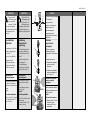
Montage
Zulässige Einbaulagen
Für Ventile:
DN 15 - 80
Mediumstemperaturen
bis 120 °C
Für Ventile:
DN 100 - 125
und bei
DN 15 - 80,
Mediumstemperaturen
größer 120 °C
Einbauort,
Einbauschema
Vorlauf oder Rücklauf
ENGLISH
Mounting
Permissible Installation
Positions
For valves:
DN 15 - 80
medium temperatures
up to 120 °C
For valves:
DN 100 - 125
and
DN 15 - 80,
medium temperatures
>120 °C
Place and Scheme of
Installation
Supply or return flow
POLSKI
Monta¿
Dopuszczalne pozycje
monta¿u
Dla zaworów:
DN 15 80
temperatura czujnika do
120
0
C
Dla zawirów:
DN 100 125
i
DN 15 80
Temperatura czynnika jest
wy¿sza ni¿ 120
0
C
Miejsce i schemat
monta¿u
Ruroci¹g zasilaj¹cy lub
powrotny.

5
AFQM, AFQM 6
DEUTSCH
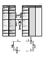
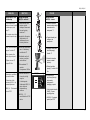
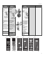
Einbau Ventil
1.Schmutzfänger vor dem
Ventil einbauen
2.Anlage vor dem Einbau
des Ventils spülen
3.Durchflussrichtung À auf
dem Ventilgehäuse
beachten
Flansche Á in der Rohr-
leitung müssen parallel,
Dichtflächen sauber und
ohne Beschädigung sein.
4. Ventil einbauen
5.Schrauben über Kreuz in
3 Stufen bis zum max.
Drehmoment anziehen
Montage Stellantrieb
AMV(E) 41. and valve
siehe Montageanleitung
AMV(E) 41 .
ENGLISH
Valve Installation
1.Install strainer in front of
valve.
2.Rinse system before
installing valve.
3.Observe flow direction À
on the valve body.
Flanges Á in the pipeline
system must be in parallel
direction, the sealing
surfaces must be clean and
undamaged.
4. Install valve.
5.Tighten screws crosswise
in 3 steps up to the
maximum torque.
Actuator AMV(E) 41. and
Valve Mounting
see Instructions
AMV(E) 41..
Á
À
POLSKI
Monta¿ zaworu
1. Zamontowaæ filtr przed
regulatorem.
2. Przed zamontowaniem
zaworu przep³ukaæ
instalacjê.
3. Zwróciæ uwagê na
wskanik kierunku
przep³ywu na korpusie
zaworu
À.
Ko³nierze Á na ruroci¹gu
musz¹ byæ wzajemnie
równoleg³e, a
powierzchnie pod
uszczelki czyste i bez
uszkodzeñ.
4. Zamontowaæ zawór
5. Dokrêcaæ przeciwleg³e
nakrêtki w 3 krokach do
osi¹gniêcia
maksymalnego momentu.
Monta¿ si³ownika
AMV(E) 41. oraz zaworu.
see Instructions
AMV(E) 41..

6
AFQM, AFQM 6
DEUTSCH
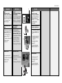
Montage Stellantrieb
AMV(E)6.. und Ventil
1. Stellantrieb am Ventil
ansetzen und mit
niedrigem Drehmoment
bis zum Anschlag
eindrehen À
ûdadurch die Stange des
Stellantriebs in die
Ventilstange bis zum
Anschlag eindrehen
2.danach den Stellantrieb
um ca. 1 Umdrehung
zurückdrehen
Á
3.Stellantrieb am Ventil
ansetzen, ausrichten
und andrücken *
4.Überwurfmutter
Â
anziehen
Anzugsmoment 100 Nm
* falls das Andrücken zu
schwer ist, wie folgt
vorgehen:
Schubstange des
Stellantriebs AMV(E) 6..
durch elektrische
Handverstellung
einfahren:
AMV(E) 6..
Ã,
ansschließend auf STOP
drehen
À
ENGLISH
Actuator AMV(E)6.. and
Valve Mounting
1. Place actuator at the
valve and screw it in with
a low torque up to its
stop À.
ûThe actuator stem is thus
screwed in up to its stop.
2.Then, re-turn actuator by
approx. 1 rotation
Á.
3.Place actuator at the
valve, align and press *
4.Tighten union nut
Â,
torque 100 Nm
* if pressing is too difficult,
proceed as follows:
Retract stem of the
actuator AMV(E) 6.. by
manual adjustment:
AMV(E) 6..
Ã, afterwards
turn to STOP
Â
46 mm
Á
POLSKI
Monta¿ si³ownika
AMV(E)6.. i zaworu
1. Umieciæ si³ownik na
zaworze i wkrêciæ ma³ym
momentem a¿ do
zatrzymania À.
û Trzpieñ si³ownika jest
cofniêty a¿ do
zatrzymania
2. Nastêpnie zrobiæ jeden
obrót odkrêcaj¹cy
si³ownik
Á.
3. Umieciæ si³ownik na
zaworze, ustawiæ i
nacisn¹æ
*
4. Dokrêciæ nakrêtk¹
³¹cz¹c¹
Â, moment 100
Nm
*
W przypadku gdy
przyciniêcie jest zbyt
trudne nale¿y
postêpowaæ w
nastêpuj¹cy sposób:
Cofn¹æ trzpieñ si³ownika
AMV(E) 6.. przez
regulacjê rêczn¹:
AMV(E) 6..
à nastêpnie
przekrêæ na STOP
Ã
OPEN
STOP
AUTO
STOP
CLOSE
AMV(E) 6..

7
AFQM, AFQM 6
DEUTSCH
Isolierung
Keinesfalls den elektrischen
Stellantrieb isolieren.
Der Druckantrieb kann bis
100 °C Mediums-
temperatur isoliert werden.
Dichtheits-,
Druckprüfung
Vor Druckprüfungen das
Ventil unbedingt öffnen
Nichtbeachtung kann zu
Schäden am Regler AFQM
führen.
Ventil öffnen mit dem
Stellantrieb AMV(E) 6..
1.Drehschalter auf Stellung
“OPEN”
À drehen
û Ventil öffnet
2.Hubanzeige beachten
Á
Ventil öffnen mit dem
Stellantriebs AMV(E) 4..
1.Taster drücken
Â
û Ventil öffnet
2.Hubanzeige
à beachten
ENGLISH
Insulation
DO NOT insulate the
electrical actuator!
The pressure actuator
may be insulated up to a
medium temperature of
100 °C.
Leak and Pressure
Tests
Prior to pressure tests
it is absolutely necessary
to open the valve.
Non-compliance may cause
damages at the controller
AFQM.
Open valve by means of
the actuator AMV(E) 6..
1.Turn rotary switch to
position “OPEN”
À.
û Valve opens
2.Observe stroke
indicator
Á .
Open valve by means of
the actuator AMV(E) 4..
1.Press push-button
Â.
û Valve opens
2.Observe stroke
indicator
Ã.
POLSKI
Izolacja
NIE izolowaæ si³ownika!
Dla temperatur czynnika do
100
o
C napêd cinieniowy
mo¿e zostaæ zaizolowany.
Próba cinieniowa i
szczelnoci
Przed przyst¹pieniem do
prób cinieniowych
absolutnie konieczne jest
otworzenie zaworu.
Nie przestrzeganie
powy¿szego mo¿e
spowodowaæ zniszczenie
regulatora AFQM.
Otwieranie zaworu, przy
u¿yciu si³ownika AMV(E)6.
1. Przestawiæ prze³¹cznik
obrotowy na pozycjê
OPEN
À.
û Zawór otwiera siê
2. Nale¿y obserwowaæ
wskanik po³o¿enia
Á.
Otwieranie zaworu przy
u¿yciu si³ownika AMV(E) 4..
1. Nacisn¹æ przycisk Â.
û Zawór otwiera siê
2. Nale¿y obserwowaæ
wskanik po³o¿enia
Ã.
Á
AMV(E) 4..
OPEN
STOP
AU TO
STOP
CLOSE
À
Ã
Â
AMV(E) 6..

8
AFQM, AFQM 6
DEUTSCH
Mit eingebauter
Steuerleitung darf
der max. Betriebsbsdruck
von 25 bar nicht
überschritten werden.
Nichtbeachtung kann zu
Undichtheit am Antrieb
führen.
Bei höheren Prüfdrücken
müssen die Steuerleitun-
gen
À am Ventil entfernt
werden.
Die Anschlüsse am Ventil
mit Stopfen G ¼ ISO 228
Á
schließen.
Nenndruck  des Ventils
beachten.
Max. Prüfdruck ist
1,5 x PN
Füllung der Anlage
Inbetriebnahme
Vorher sicherstellen, dass
das Ventil auf ist,
siehe Seite 7
À
Á
Â
ENGLISH
When the impulse tube is
installed, the max.
operating pressure of
25 bar must NOT be
exceeded.
Non-compliance may cause
leaks at the actuator.
In case of higher test
pressures, remove impulse
tubes
À at the valve.
Close connections at the
valve with plug G ¼ ISO
228
Á.
Observe nominal pressure
 of the valve.
Max. test pressure is
1.5 x PN
Filling the System
First Start-up
First, ensure that valve is
open, see page 7.
POLSKI
Kiedy rurki impulsowe s¹
pod³¹czone maksymalne
cinienie robocze 25 bar
nie mo¿e byæ przekroczone.
Nieprzestrzeganie
powy¿szego mo¿e
spowodowaæ zniszczenie
si³ownika.
Dla wy¿szych cinieñ
próbnych, nale¿y od³¹czyæ
rurki impulsowe
À od
zaworu.
Otwory zakorkowaæ
zalepkami z gwintem G ¼
ISO 228 Á.
Sprawdziæ wartoæ cinienia
nominalnego  na korpusie
zaworu. Max. cinienie
próbne wynosi 1,5 x PN
Nape³nianie uk³adu
pierwsze
uruchomienie
Najpierw upewniæ siê ¿e
zawór jest otwarty, patrz str.
7.

9
AFQM, AFQM 6
DEUTSCH
Der Druck Ä am
Ventilausgang darf
den Druck à am
Ventileingang nur
geringfügig überschreiten.
Nichtbeachtung kann zu
Schäden am Regler führen.
Einstellung
Volumenstrom-
begrenzung
Die Einstellung des Volu-
menstroms erfolgt über
die Einstellung des Ventil-
hubes
À .
Es gibt 2 Möglichkeiten:
1.Einstellung mit
Einstelldiagramm
2.Einstellung mit Wärme-
zähler, siehe Seite 10
Einstellung mit
Einstelldiagramm
Die Anlage muss zur Ein-
stellung nicht in Betrieb
sein.
Die Einstellung erfolgt in
zwei Schritten
Schritt 1:
Einstellung Ventilhub
1.Ventil
Á schließen durch
Drehen der
Einstellschraube
 bis
zum Anschlag.
ENGLISH
The pressure Ä
at the valve output
may exceed the
pressure
à at the
valve input only isignifi-
cantly. Non-compliance may
cause damages at the
controller.
Flow Limitation
Adjustment
The adjustment of the flow
is made by adjusting the
valve stroke
À.
There are 2 possibilities:
1.Adjustment with
adjustment diagram
2.Adjustment with heat
meter, see page 10.
Adjustment with
adjustment diagram
The system need not be in
operation for adjustment.
Adjustment is performed in
2 steps:
Step 1:
Valve stroke adjustment
1.Close valve
Á by turning
the adjusting screw Â
up to its stop.
POLSKI
Cinienie na wyjciu zaworu
Ä mo¿e tylko
nieznacznie byæ
wy¿sze od cinienia na
wejciu zaworu
Ã.
Nieprzestrzeganie
powy¿szego mo¿e
spowodowaæ zniszczenie
regulatora.
Nastawa
ograniczenia
przep³ywu
Wielkoæ przep³ywu
zadawana jest przez
ograniczenie skoku zaworu
À.
Istniej¹ dwie metody:
1. Nastawa na podstawie
wykresu regulacji
przep³ywu
2. Nastawa na podstawie
wskazañ ciep³omierza,
patrz strona 10
Nastawa na podstawie
wykresu regulacji
przep³ywu
Uk³ad nie mo¿e pracowaæ w
trakcie zadawania nastawy.
Nastawa realizowana jest w
dwóch krokach:
Krok 1:
Nastawa skoku zaworu:
1. Zamkn¹æ zawór
Á przez
dokrêcenie ruby
nastawczej
 do jej
zatrzymania.
Â
AFQM 6
à Ä
Â
AFQM
27 mm
Á
À

10
AFQM, AFQM 6
DEUTSCH
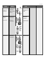
2. Diagramm unten
auswählen
3.Einstellschraube
À um
diese Anzahl No nach
rechts drehen
ûEinstellung des Ventil-
hubes ist abgeschlossen
4.Einstellschraube
À kann
plombiert werden
(Bohrung)
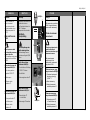
Einstelldiagramme
erforderlicher
Volumenstrom
Umdrehungen
Einstelldrossel No
ENGLISH
2. Select diagram below.
3.Turn adjusting screw
À
by the No number to the
right.
ûThe adjustment of the
valve stroke is completed.
4.The adjusting screw
À
may be sealed (drilling).
Adjustment diagrams
necessary
flow
No of rotations of
adjusting throttle
POLSKI
2. Wybraæ wykres poni¿ej
Wymagany
przep³yw
Iloæ obrotów ruby
nastawczej No
3. Wykrêciæ rubê nastawcz¹
À o odczytan¹ iloæ
obrotów (obroty przeciwne
do ruchu wskazówek
zegara).
û Nastawa skoku zaworu
zakoñczona.
4. ruba regulacyjna
À
mo¿e zostaæ
zaplombowana.
Wykresy regulacji
przep³ywu
À
À
AFQM 6
AFQM
100
70
50
30
20
10
7
5
3
2
1
DN40/50
ÐP
b
0.2 bar
124
100
70
50
30
20
10
7
5
3
2
1
DN40/50
ÐP
b
0.5 bar
124
6
6
[m
3
/h]
[m
3
/h]
No No
0
60
40
0 2 4 6 8 10 12 14
20
50
30
10
0
60
40
01234567891011
20
50
30
10
0
70
50
0
80
60
0 2 4 6 8 10 12 14
20
30
10
40
90
100
70
50
80
60
0 2 4 6 8 10 12 14
20
30
10
40
90
100
110
120
130
ÐP
b
0.5 bar
ÐP
b
0.2 bar
[m
3
/h]
ÐP
b
0.5 bar
ÐP
b
0.2 bar
ÐP
b
0.5 bar
ÐP
b
0.2 bar
ÐP
b
0.5 bar
ÐP
b
0.2 bar
DN 100 DN 125DN 80DN 65
[m
3
/h]
[m
3
/h]
[m
3
/h]
No No No No
DN 40 / 50

11
AFQM, AFQM 6
DEUTSCH
Schritt 2
Einstellung der Endlagen
am Stellantrieb
siehe Bedienungsanleitung
“Elektrischer Stellantrieb
AMV(E) 6.., 4..”, Abschnitt:
“Einstellung der Endlagen”
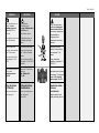
Einstellung mit
Wärmezähler
1.Schubstange des
Stellantriebs einfahren:
Stellantrieb AMV(E, -H) 6..
- Drehschalter auf Stellung
“OPEN”
À drehen,
dadurch die Schub-
stange Á einfahren.
- Hubanzeige  beachten
Stellantrieb AMV 4..
- Taster drücken
à ,
dadurch die Schubstange
Ä einfahren
- Hubanzeige
Å beachten
ENGLISH
Step 2
Adjustment of final
positions at the actuator
see Operating Instructions
“Electrical Actuator AMV(E)
6.., 4..”, section “Final
Position Settings”.
Adjustment with heat
meter
1.Retract stem of actuator:
Actuator AMV(E, -H) 6..
- Turn rotary switch to
position “OPEN”
À.
This retracts the stem Á.
- Observe stroke
indicator Â
Actuator AMV 4..
- Press push-button
Ã.
This retracts the stem Ä.
- Observe stroke
indicator
Å.
POLSKI
Krok 2:
Regulacja pozycji
krañcowych si³ownika
patrz Instrukcja Obs³ugi
Si³ownik elektryczny
AMV(E) 6.., 4.., rozdzia³
Nastawy pozycji
krañcowych.
Nastawa na podstawie
wskazañ ciep³omierza
1. Cofnij trzpieñ si³ownika
„ Si³ownik AMV (E, -H)
6.„
- Przestawiæ prze³¹cznik
obrotowy na pozycjê
OPEN
À .
To powoduje cofanie
trzpienia
Á.
- Nale¿y obserwowaæ
wskanik po³o¿enia
Â
Si³ownik AMV 4..
- Nacinij przycisk
Ã.
To powoduje cofanie
trzpienia Ä
- Nale¿y obserwowaæ
wskanik po³o¿enia
Å.
Á
OPEN
STOP
AU TO
STOP
CLOSE
À
Â
Ã
Ä
Å

12
AFQM, AFQM 6
DEUTSCH
2.Sicherstellen, dass die
Anlage oder ein
Bypass
À vollständig
geöffnet ist.
3.Anzeige des Wärme-
zählers beachten.
4.Erhöhung des
Volumenstroms
Á
5.Reduzierung des
Volumenstroms
Â
ENGLISH
2.Ensure that the system
or a bypass
À is
completely open.
3.Observe indicator of
heat meter.
4.Increase of flow
Á.
5.Reduction of flow Â.
POLSKI
2. Upewniæ siê ¿e uk³ad jak
równie¿ bypass
À s¹
otwarte.
3. ledziæ wskazania
licznika ciep³a.
4. Zwiêkszenie przep³ywu
Á.
5. Zmniejszenie przep³ywu
Â
À
AFQM 6
AFQM
Á
AFQM
AFQM 6
Â

13
AFQM, AFQM 6
DEUTSCH
6.Nachdem der Wärme-
zähler den geforderten
Wert anzeigt, die Anlage
kurz androsseln und
wieder öffnen, z.B. mit
dem elektrischen Stell-
antrieb.
7.Volumenstrom
überprüfen.
ûEinstellung des Ventil-
hubes ist abgeschlossen
8.Einstellschraube
À kann
plombiert werden
(Bohrung)
ENGLISH
6.As soon as the heat
meter shows the
required value, shortly
throttle the system and
re-open, e.g. with the
electrical actuator.
7.Verify flow.
ûThe adjustment of the
valve stroke is completed.
8.The adjusting screw
À
may be sealed (drilling).
POLSKI
6. Jak tylko licznik ciep³a
wska¿e wymagan¹
wartoæ, delikatnie
zd³awiæ uk³ad i ponownie
otworzyæ np. przy u¿yciu
si³ownika.
7. Zweryfikowaæ przep³yw
û Nastawa skoku zaworu
zosta³a wykonana.
8. ruba nastawcza
À
mo¿e byæ zaplombowana.
À
À
AFQM 6
AFQM
-
 1
1
-
 2
2
-
 3
3
-
 4
4
-
 5
5
-
 6
6
-
 7
7
-
 8
8
-
 9
9
-
 10
10
-
 11
11
-
 12
12
-
 13
13


in anderen Sprachen
Verwandte Artikel
-
Danfoss AMV 410, 413 Bedienungsanleitung
-
-
-
-
-
-
-
-
Danfoss AIQM Bedienungsanleitung
-