Danfoss AVQM-W, AVQMT-W Bedienungsanleitung
- Typ
- Bedienungsanleitung

Instructions
AVQM-W, AVQMT-W – PN 25 / DN 15-25
73695440 DH-SMT/SI VI.LJ.C2.5B © Danfoss 05/2009 1
ENGLISH
Flow (and temperature) controller with integrated control
valve AVQM-W, AVQMT-W
www.danfoss.com Page 7
DEUTSCH
Volumenstrom- und Temperaturregler mit eingebautem
Motorstellventil AVQM-W, AVQMT-W
www.danfoss.com Seite 9
DN 15-25 DN 15-25 DN 15-25
∆p = 0.2 ∆p = 0.2 ∆p = 0.2
AVQM-W (PN 25) AVQMT-W (PN 25) AVQMT-W/AVT (PN 25)

DN 15 20 25
SW
mm
32 (G ¾A) 41 (G 1A) 50 (G 1¼A)
d 21 26 33
R
1)
½ ¾ 1
L1
2)
130 150 160
L2 131 144 160
L3 139 154 159
k 65 75 85
d
2
14 14 14
n 4 4 4
AVQMT -W
DN 15 20 25
L
mm
65 70 75
L1 - - -
H 131 131 131
H1 - - -
H2 88 88 91
H3 - - -
AVQM-W
DN 15 20 25
L
mm
65 70 75
L1 - - -
H 109 109 109
H*
AMV(E) 10 307 - -
AMV(E) 13 304 - -
AMV(E) 2./3. (thread) 317 317 320
AMV(E) 2./3. (flange) - - -
AMV 150 305 - -
H1 - - -
H2 88 88 91
H3 - - -
Valve weight (thread)
kg
3.0 3.0 3.2
Valve weight (flange) - - -
AMV(E) 2./3. +
VQM-W (DN 15-25)
AMV 150 +
AVQM-W (DN 15-25)
AMV(E) 10 +
AVQM-W (DN 15-25)
AMV(E) 13 +
AVQM-W (DN 15-25)
73695440 DH-SMT/SI VI.LJ.C2.5B © Danfoss 05/2009 2
❾
T1

❶ ❷
❸
❹
❻
❼
①
❺
③
②
④
⑤
⑥
⑦
⑧
< 100
°
C > 100
°
C
AMV(E)
73695440 DH-SMT/SI VI.LJ.C2.5B © Danfoss 05/2009 3
DN L (mm)
15 69
20 74
25 79

M
①
③
4
③
④ ⑤
4
PN 25
①
Δp
v
③
–
+
①
②
①
< 100
°
C
> 100
°
C
②
④
4
④
⑤
⑥
4
M
❽
❿
①
⓫
⓬
⓭
M
②
PN 25
⑥
4
⑥
4
⑦ ⑧
②
①
⓮
73695440 DH-SMT/SI VI.LJ.C2.5B © Danfoss 05/2009 4

⓯
1 = 360°
1 = 360°
PN 25
1 = 360°
Δp
v
:
—
0.5 … 12 bar
_ _ _ 1.0 … 12 bar
DN 15 k
VS
2.5 DN 15 k
vs
4.0
DN 20 k
vs
6.3 DN 25 k
vs
8.0
73695440 DH-SMT/SI VI.LJ.C2.5B © Danfoss 05/2009 5

6 VI.LJ.C2.5B © Danfoss 05/2009 73695440 DH-SMT/SI
DEUTSCH
DEUTSCH
Sicherheitshinweise
Um Verletzungen an Personen und
Schäden am Gerät zu vermeiden, ist diese
Anleitung vor der Montage unbedingt zu
beachten.
Montage, Inbetriebnahme und
Wartungsarbeiten dürfen nur von
sachkundigen und autorisierten Personen
durchgeführt werden.
Vor Montage und Wartungsarbeiten am
Regler die Anlage:
- drucklos machen,
- abkühlen,
- entleeren und
- reinigen.
Die Vorgaben des Anlagenherstellers und
Anlagenbetreibers sind zu beachten.
Anwendungsbereich
Der Regler wird in Verbindung mit
elektrischen Stellantrieben AMV(E) zur
Volumenstrom- und Temperaturregelung
von Wasser und Wasser-Glykol-
Mischungen in Heizungs-, Fernwärme- und
Kühlungsanlagen verwendet.
AVQM-W(T) PN 25 kann mit den
elektrischen Stellantrieben AMV(E) 10/13
(nur DN15), AMV(E) 20/23, AMV 20/23 SL,
AMV(E) 30/33, AMV 30, AMV 150 kombiniert
werden.
AVQMT-W PN 25 kann mit dem
Temperaturregler AVT bzw. mit dem
Sicherheitstemperaturwächter (Antrieb)
STM kombiniert werden.
Die auf dem Typenschild angegebenen
technischen Daten bestimmen den Einsatz.
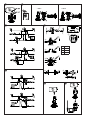
Montage
Zulässige Temperatur ❶
Zulässige Einbaulagen ❷
Mediumstemperaturen bis 100 °C ①:
- Die Einbaulage mit nach unten
hängendem elektrischen Stellantrieb ist
nicht zulässig!
Mediumstemperaturen > 100 °C ②:
- Einbau nur in waagerechte Rohrleitung
mit nach unten hängendem
Druckantrieb zulässig.
Weiteres:
Instruktionen für den elektrischen
Stellantrieb AMV(E) beachten.
Beim AVQMT-W Regler ebenfalls
die Instruktionen für den
Temperaturregler AVT bzw. für den
Sicherheitstemperaturwächter (Antrieb)
STM beachten.
Einbauort, Einbauschema
AVQM-W(T) Einbau im Rücklauf ❸
AVQM-W(T) Einbau im Vorlauf ❹
Einbau Ventil ❺
1. Rohrleitung vor der Montage reinigen.
2. Der Einbau eines Schmutzfängers ① vor
dem Regler wird dringend empfohlen.
3. Ventil einbauen
• Durchussrichtung② auf dem
Typenschild oder Ventil beachten ③.
• Ventilmitangeschraubten
Anschweißenden nur an die
Rohrleitung anheften ④.
Das Einschweißen der
Anschweißenden ist nur ohne Ventil
und Dichtungen zulässig! ⑤⑥
Bei Nichtbeachtung zerstören die
hohen Schweißtemperaturen die
Dichtungen des Ventils.
• Flansche⑦ in der Rohrleitung müssen
parallel, Dichtflächen sauber und ohne
Beschädigungen sein.
Schrauben über Kreuz in 3 Stufen bis
zum max. Drehmoment anziehen
(50 Nm).
4. Achtung:
Mechanische Belastungen des
Ventilgehäuses durch die Rohrleitungen
sind nicht zulässig ⑧.
Einbau elektrischer Stellantrieb ❻
Elektrischen Stellantrieb AMV(E) auf das
Ventil montieren und Überwurfmutter mit
Mutternschlüssel SW 32 anziehen.
Anzugsmoment 25 Nm.
Weiteres:
Instruktion für den elektrischen
Stellantrieb AMV(E) beachten.
Einbau Thermostat ❼
(maßgebend nur bei AVQMT-W Reglern)
Den Temperaturregler AVT bzw.
STM auf die Membran legen und die
Überwurfmutter mit Schraubenschlüssel
SW 50 festziehen.
Drehmoment 35 Nm.
Weiteres:
Instruktionen für den Temperaturregler
AVT bzw. STM beachten.
Isolierung ❽
Bei Mediumstemperaturen bis 100 °C kann
auch der Druckantrieb ① isoliert werden.
Die Isolierung des elektrischen
Stellantriebes ② ist nicht zulässig!
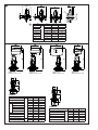
Abmessungen, Gewichte ❾
1)
Kegeliges Außengewinde nach
EN 10226-1
2)
Flansche PN 25, nach EN 1092-2
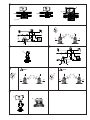
Inbetriebnahme ❿
Füllung der Anlage, Inbetriebnahme
1. Ventile in der Anlage öffnen.
2. Absperrarmaturen ① im Vorlauf
langsam öffnen.
3. Abperrarmaturen ② im Rücklauf
langsam öffnen.
Dichtheits- und Druckprüfung
Das geschlossene Regelventil nicht mit
Druck über 16 bar prüfen. Das Ventil kann
sonst beschädigt werden.
Druckprüfungen sollten vor dem Einbau
des elektrischen Stellantriebs durchgeführt
werden. Dies stellt sicher, dass das Ventil
geöffnet ist.
Vor Durchführung der Druckprüfung, die
Einstellschraube ④ durch Drehen öffnen:
- Linksdrehung (entgegen der
Uhrzeigerrichtung) ⑤ am Regler
PN 25 oder Rechtsdrehung (in
Uhrzeigerrichtung) ⑥
Druckerhöhung muss am (+/-)
Anschluss ③ gleichmäßig erfolgen.
Nichtbeachtung kann zu Schäden am
Druckantrieb und/oder Ventil führen.
Die Druckprüfung der Anlage muss nach
den Vorgaben des Anlagenherstellers
durchgeführt werden.
Max. Prüfdruck ist: 1,5 × PN
PN siehe Typenschild!
Außerbetriebnahme
1. Absperrarmaturen ① im Vorlauf
langsam schließen.
2. Absperrarmaturen ② im Rücklauf
langsam schließen.

73695440 DH-SMT/SI VI.LJ.C2.5B © Danfoss 05/2009 7
Einstellung Sollwerte
Einstellung Volumenstrom ⓫
Die Einstellung des Volumenstroms
erfolgt über die Einstellung des Hubes der
Einstellschraube ①.
Es gibt zwei Möglichkeiten:
1. Einstellung mit Einstelldiagramm,
2. Einstellen mit dem Wärmezähler.
Voraussetzung ⓬
(Min. Differenzdruck über dem Ventil)
Die Druckdifferenz Δp
v
① über dem
Regelventil muss bei max. Volumenstrom
mindestens betragen: ∆p
min
= 0,5 bar
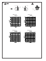
Einstellung mit Einstelldiagramm ⓭
Die Anlage muss zur Einstellung nicht in
Betrieb sein.
1. Das Regelventil ① durch Drehen der
Einstellschraube ③ bis zum Anschlag
schließen:
- Rechtsdrehung (in Uhrzeigerrichtung)
④ am Regler PN 25 oder Linksdrehung
(entgegen der Uhrzeigerrichtung) ⑤
2. Einstelldiagramm (siehe ⓯) auswählen.
No
erforderlicher
Volumenstrom
Umdrehungen
Einstelldrossel
PN 25 : 1 = 360°
3. Das Regelventil ② durch vorgegebene
Anzahl von Drehungen der
Einstellschraube ⑥ öffnen:
• Linksdrehung(entgegender
Uhrzeigerrichtung) ⑦ am Regler
PN 25 oder Rechtsdrehung (in
Uhrzeigerrichtung) ⑧
4. Die Einstellung des Volumenstromes
ist abgeschlossen; die Einstellschraube
kann plombiert werden. Weiter
mit Schritt 2, Einstellen mit dem
Wärmezähler.
Die Einstellung kann bei in Betrieb
genommener Anlage über einen
Wärmezähler überprüft werden, siehe
nächsten Abschnitt.
Einstelldiagramme PN 25 ⓯
Einstellung mit Wärmezähler
Voraussetzung:
Die Einstellung sollte durchgeführt werden,
wenn der elektrische Stellantrieb AMV(E)
noch nicht montiert ist. Falls der elektrische
Stellantrieb bereits eingebaut ist, muss
seine Antriebsstange komplett eingefahren
werden.
Die Anlage muss in Betrieb sein. Armaturen
in der Anlage oder ein Bypass müssen
vollständig geöffnet sein.
1. Beachten Sie den Wärmeanzeiger. ⓭
Am Regler PN 25:
- Linksdrehung (entgegen
der Uhrzeigerrichtung) ⑦
oder Rechtsdrehung (in
Uhrzeigerrichtung) ⑧ erhöht den
Durchfluss
- Rechtsdrehung (in Uhrzeigerrichtung)
④ oder Linksdrehung (entgegen der
Uhrzeigerrichtung) ⑤ verringert den
Durchfluss.
Nach abgeschlossener Einstellung ⓮
:
2. Falls noch nicht eingebaut, Antrieb
montieren ①, siehe Abschnitt Einbau
elektrischer Stellantrieb.
3. Die Anlage kurz drosseln und dann
wieder öffnen (durch elektrischen
Stellantrieb).
4. Volumenstrom prüfen.
Die Einstellung des Regelventils ist
abgeschlossen.
5. Die Einstellschraube ② kann plombiert
werden.
Temperatureinstellung
(maßgebend nur bei AVQMT-W Reglern)
Instruktionen für den
Temperaturregler AVT bzw. für den
Sicherheitstemperaturwächter (Antrieb)
STM beachten.

8 VI.LJ.C2.5B © Danfoss 05/2009 73695440 DH-SMT/SI
DEUTSCH
ENGLISH
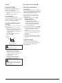
Safety Notes
Prior to assembly and commissioning to
avoid injury of persons and damages of
the devices, it is absolutely necessary
to
carefully read and observe these instructions.
Necessary assembly, start-up, and
maintenance work must be performed
only by qualified, trained and authorized
personnel.
Prior to assembly and maintenance work
on the controller, the system must be:
- depressurized,
- cooled down,
- emptied and
- cleaned.
Please comply with the instructions of the
system manufacturer or system operator.
Definition of Application
The controller is in combination with
electrical actuators (AMV(E) used for flow
and temperature control of water and
water glycol mixtures for heating, district
heating and cooling systems.
AVQM-W(T) PN 25 could be combined
with electrical actuators AMV(E) 10/13
(DN15 only), AMV(E) 20/23, AMV 20/23 SL,
AMV(E) 30/33, AMV 30, AMV 150.
AVQMT-W PN 25 could be combined
with temperature actuator AVT or safety
temperature monitor (actuator) STM.
The technical parameters on the product
labels determine the use.
Assembly
Admissible Temperatures ❶
Admissible Installation Positions ❷
Medium temperatures up to 100 °C:
- Can be installed in any position,
except
with electrical actuator oriented
downwards.
Medium temperatures > 100 °C:
- Installation permitted only in horizontal
pipelines with the electrical actuator
oriented upwards.
Other details:
See instructions for electrical actuator
AMV(E). In case of AVQMT-W controller see
instructions for temperature actuator AVT
or safety temperature monitor (actuator)
STM as well.
Installation Location and
Installation Scheme
AVQM-W(T) return mounting ❸
AVQM-W(T) flow mounting ❹
Valve Installation ❺
1. Clean pipeline system prior to assembly.
2. The installation of a strainer ① in
front of the controller is strongly
recommended.
3. Install valve
• Theowdirectionindicatedonthe
product label ② or on the valve ③
must be observed.
• Thevalvewithmountedweld-on
tailpieces may only be spot welded to
the pipeline ④.
The weld-on tailpieces may be welded
only without the valve and seals! ⑤⑥
If these instructions are not observed,
high welding temperatures may
destroy the seals.
• Flanges⑦ in the pipeline must be in
parallel position and sealing surfaces
must be clean and without any
damage.
Tighten screws in flanges crosswise
in 3 steps up to the maximum torque
(50 Nm).
4. Caution:
Mechanical loads of the valve body by the
pipelines are not permitted ⑧.
Mounting of electrical actuator ❻
Place electrical actuator AMV(E) on the
valve and tighten union nut with wrench
SW 32.
Torque 25 Nm.
Other details:
See instructions for electrical actuator
AMV(E).
Mounting of temperature
actuator ❼
(relevant only at AVQMT-W controllers)
Place temperature actuator AVT or STM at
the diaphragm and tighten union nut with
wrench SW 50.
Torque 35 Nm.
Other details:
See instructions for temperature actuator
AVT or STM.
Insulation ❽
For medium temperatures up to 100 °C the
pressure actuator ① may also be insulated.
Insulation of electrical actuator ② AMV(E)
is not allowed.
Dimensions, Weights ❾
1)
Conical ext. thread acc. to EN 10226-1
2)
Flanges PN 25, acc. to EN 1092-2
Start-up ❿
Filling the system, first start-up
1. Open valves in the system.
2. Slowly open shut-off devices ① in the
flow pipeline.
3. Slowly open shut-off devices ② in the
return pipeline.
Leak and Pressure Tests
Do not test closed control valve with
pressures of more than 16 bar. Otherwise,
the valve may be damaged.
Pressure tests should be carried out prior
to the installation of the electrical actuator.
This guarantees that the valve is opened.
Before pressure test, open the adjustable
flow restrictor ④ by turning it:
- at PN 25 controller to the left
(counter clockwise) ⑤ or to the right
(clockwise) ⑥
Pressure must be gradually increased at
the (+/-) connection ③.
Non-compliance may cause damages at
the actuator or the valve.
A pressure test of the entire system
must be carried out in accordance with
manufacturer’s instructions.
The maximum test pressure is: 1.5 × PN
PN-see product label!
Putting out of operation
1. Slowly close shut-off devices ① in the
flow pipeline.
2. Slowly close shut-off devices ② in the
return pipeline.

73695440 DH-SMT/SI VI.LJ.C2.5B © Danfoss 05/2009 9
Settings
Flow Rate Setting ⓫
The flow rate is adjusted by means of
limitation of control valve stroke ①.
There are two possibilities:
1. Adjustment with the flow adjusting
curves,
2. Adjustment with heat meter.
Pre-condition ⓬
(min. diff. pressure over the valve)
To achieve maximum flow rate the pressure
difference Δp
v
① across the control valve
must be at least: ∆p
min
= 0.5 bar
Adjustment with flow adjusting
curves ⓭
The system don’t need to be active for
being adjusted.
1. Close control valve ① by turning the
adjustable flow restrictor ③ to its stop:
- at PN 25 controller to the right
(clockwise) ④ or to the left (counter
clockwise) ⑤
2. Select flow adjusting curve in the
diagram (see ⓯ ).
No
Necessary
flow rate
Revolutions of
adjusting throttle
For PN 25 controller: 1 = 360°
3. Open control valve ② with the
adjustable flow restrictor ⑥ by
determined number of revolutions:
• atPN25controllertotheleft(counter
clockwise) ⑦ or to the right
(clockwise) ⑧
4. The setting of the valve stroke is
completed, continue with step 2,
Adjustment with Heat Meter.
The setting may be verified with help of a
heat meter if the system is in operation,
see next section.
Flow Adjusting Curves PN 25 ⓯
Adjustment with Heat Meter
Pre-condition:
The setting should be carried out when the
electrical actuator AMV(E) is dismounted. If
the electrical actuator is mounted, the stem
of the actuator must be retracted.
The system must be in operation. All
units in the system or a bypass must be
completely open.
1. Observe heat meter indicator. ⓭
At PN 25 controller:
- turning to the left (counter
clockwise) ⑦ or to the right
(clockwise) ⑧ increases the flow rate
- turning to the right (clockwise) ④
or to the left (counter clockwise) ⑤
decreases the flow rate.
After the adjustment has been completed ⓮
:
2. If not yet done, install the actuator ①,
see section Mounting of electrical
actuator.
3. Shortly throttle the system and then re-
open it (e.g. by means of the electrical
actuator).
4. Verify flow rate.
The control valve setting is completed.
5. The adjustable flow restrictor ② may be
sealed.
Temperature setting
(relevant only at AVQMT-W controllers)
See instructions for temperature actuator
AVT or safety temperature monitor
(actuator) STM.

10 VI.LJ.C2.5B © Danfoss 05/2009 73695440 DH-SMT/SI

73695440 DH-SMT/SI VI.LJ.C2.5B © Danfoss 05/2009 11

12 VI.LJ.C2.5B
Produced by Danfoss A/S © 05/2009
-
 1
1
-
 2
2
-
 3
3
-
 4
4
-
 5
5
-
 6
6
-
 7
7
-
 8
8
-
 9
9
-
 10
10
-
 11
11
-
 12
12


Danfoss AVQM-W, AVQMT-W Bedienungsanleitung
- Typ
- Bedienungsanleitung
in anderen Sprachen
Verwandte Artikel
-
Danfoss AVQM, AVQMT (Generation 2006) Bedienungsanleitung
-
-
-
-
-
-
-
-
-