Danfoss AMV 410, AMV 413 Bedienungsanleitung
- Typ
- Bedienungsanleitung

Instructions
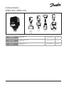
AMV 410, AMV 413
73696000 DH-SMT/SI VI.AA.U3.7R © Danfoss 10/2008 1
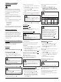
VFG 2 VFU 2 VFGS 2 AFQM 6
VFG 21
VFG 25
ENGLISH
Electrical Actuators
AMV 410, 413
www.danfoss.com Page 5
DEUTSCH
Elektrischer Stellantrieb
AMV 410, 413
www.danfoss.de Seite 6
POLSKI
Siłownik elektryczny
AMV 410, 413
www.danfoss.pl Strona 7

AFQM 6
(DN 40, 50)
VFU 2
VFG 2 (21), (25)
AFQM 6
(DN 40, 50)
VFU 2
VFG 2 (21), (25)
1
2 3
4
73696000 DH-SMT/SI VI.AA.U3.7R © Danfoss 10/2008 2
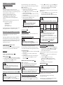
VFGS 2DN 15 - 80
> 120 °C
DN 15 - 80
< 120 °C
VFG (DN 15-80) VFU 2 (DN 15-80)
VFGS 2 (DN 15-80)
AFQM 6 (DN 40, 50)

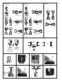
Power supply
230 V AC
with connection of STB/SDW
remove jumper
to from
controller
open
close
open
stroke
close
open
close
Power supply
230 V AC
with connection of STB/SDW
remove jumper
to from
controller
open
close
open
close
open
stroke
close
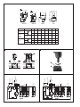
5 7
8
6
73696000 DH-SMT/SI VI.AA.U3.7R © Danfoss 10/2008 3
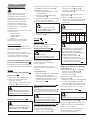
AMV 413 AMV 410 VFG(S) VFU
Type DN 15 20 25 32 40 50 65 80
VFG..
VFU 2
L
mm
130 250 260 280 200 230 290 310
VFG 2
VFG 21
VFG 25
VFGS 2
B 212 212 238 238 240 240 275 275
kg 7 9 10 13 17 22 33 41
VFU 2
B
mm
95 95 106 106 123 123 135 135
C 311 311 337 337 339 339 374 374
kg 7 9 10 13 17 22 33 41

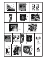
3 mm
10
9
11
73696000 DH-SMT/SI VI.AA.U3.7R © Danfoss 10/2008 4

73696000 DH-SMT/SI VI.AA.U3.7R © Danfoss 10/2008 5
DANSKENGLISH
Safety Notes
Prior to assembly and commissioning
to avoid injury of persons and damages
of the devices, it is absolutely necessary
to carefully read and observe these
instructions.
Necessary assembly, start-up, and
maintenance work must be performed
only by qualified, trained and authorized
personnel.
Prior to assembly and maintenance work
on the controller, the system must be:
- depressurized,
- cooled down,
- emptied and
- cleaned.
Please comply with the instructions of the
system manufacturer or system operator.
Definition of Application
The electrical actuator is used in
connection with the following valves:
VFG 2(21), VFG 25, VFU 2, VFGS 2, AFQM 6.
Fields of application are the temperature
control of water, water-glycol mixtures
and steam for heating, district heating and
cooling systems.
Safety Return Function and Effective
Direction
2
Safety function and effective direction of
stem: valid only for AMV 413.
Mounting
Permissible Installation Positions
1
Valve Installation
3
1. Install strainer in front of valve.
2. Rinse system before installing valve.
3. Observe flow direction on the valve
body.
Flanges in the pipeline system must be
in parallel direction, the sealing surfaces
must be clean and undamaged.
4. Install valve.
Actuator and Valve Installation
4
The actuator must only be mounted with
the stem retracted
.
Stroke indicator
must be in position .
On delivery the stem is retracted with a
screwed-in mounting screw .
If this is not the case, then:
1. Carry out the electrical connection, see
next section.
2. Press push-button and completely
retract the stem .
3. Screw in mounting screw up to its
stop.
4. Place actuator on the valve and align.
5. Tighten union nut torque 100 Nm.
6.
It is absolutely necessary to unscrew
the mounting screw
, otherwise, the
actuator is out of function.
7. If the actuator is installed in a downward
hanging position , remove label .
Insulation
5
Dimensions
6
Flanges: connection dimensions acc. to
EN 1092-2, seal form C.
Electrical Connection
7
HIGH VOLTAGE !
Danger of injury and life in case of
improper handling.
Switch off power supply prior to
connecting lines.
The electrical connection must only be
performed by an expert electrician.
Procedure
1.
Unscrew cap nut and remove cover .
2. Connect lines in accordance with
connection diagram.
3. Prior to remounting the cover, carry out
settings at the actuator, see part
8
.
Electrical Connection Diagram
8
Connection for:
STB - Safety Temperature Limiter
STW - Safety Temperature Monitor
SDB - Safety Pressure Limiter
Prior to connection, it is absolutely necessary
to remove the jumper (terminals 4-7).
Only types AMV 413 with safety return
function.
Mechanical Stroke Setting
9
The stroke of the electrical actuator must
be adjusted to the valve stroke.
1. Unscrew the mounting screw .
2. Press push-button until the valve
is completely closed (VFU 2
completely
open) and the direction
indicator stops.
Observe stroke indicator, it must move to
position .
3. Turn the screw until the cam
with line of the selected stroke is
aligned with the actuator of the end
switch.
Note:
Select the valve stroke from the table below.
Type DN 15 20 25 32 40 50 65 80
VFG 2
VFG 21
VFG 25
AFQM 6
mm
6 8 12 18
VFU 2 8 10 14 20
Note:
Only special actuator types are equipped
with end switches, see rating plate.
The adjustment of the end switches must
be done after the stroke has been set.
a. Unscrew the »Allen key« screw
b. Adjust the stroke of the electrical
actuator regarding to chapter:
”Mechanical stroke setting”
Adjusting the Additional
End Switch
10
1. Press push-button until the valve
is completely closed (VFU 2
completely open) and the direction
indicator stops.
Observe stroke indicator, it must move to
position .
2. Connect terminals 14 and 16 to an
ohmmeter .
3. Turn screw until the cam switches
the end switch and the ohmmeter
shows 0 Ω.
The end switches are adjusted.
Dismounting of Valve and
Actuator
11
DANGER!
Danger of injury by steam or hot water!
Valve without actuator is open , sealing
is in the actuator.
It is absolutely necessary to depressurize
system prior to dismounting.
Carry out dismounting in reverse order as
mounting.
9

73696000 DH-SMT/SI VI.AA.U3.7R © Danfoss 10/2008 6
DEUTSCH
Sicherheitshinweise
Um Verletzungen an Personen und
Schäden am Gerät zu vermeiden, ist diese
Anleitung unbedingt vor der Montage und
Inbetriebnahme zu beachten.
Montage, Inbetriebnahme und
Wartungsarbeiten dürfen nur von
sachkundigen, geschulten und
autorisierten Personen durchgeführt
werden.
Vor Montage und Wartungsarbeiten am
Regler muss die Anlage:
- drucklos gemacht,
- abgekühlt,
- geleert und
- gereinigt werden.
Die Vorgaben des Anlagenherstellers und
Anlagenbetreibers sind zu beachten.
Bestimmungsgemäße Verwendung
Der elektrische Stellantrieb wird in
Verbindung mit folgenden Ventilen
eingesetzt:
VFG 2(21), VFG 25, VFU 2, VFGS 2, AFQM 6.
Einsatzgebiete sind Temperaturregelung
von Wasser, Wasser-Glykolgemischen und
Dampf für Heizungs-, Fernheizungs- und
Kühlungsanlagen.
Sicherheitsfunktion und
Wirkrichtung
2
Sicherheitsfunktion und Wirkrichtung der
Antriebsstange: gilt nur für AMV 413.
Montage
Zulässige Einbaulagen
1
Einbau Ventil
3
1.
Schmutzfänger vor dem Ventil einbauen.
2.
Anlage vor dem Einbau des Ventils spülen.
3. Durchflussrichtung auf dem
Ventilgehäuse beachten.
Flansche in der Rohrleitung müssen
parallel, Dichtflächen sauber und ohne
Beschädigung sein.
4. Ventil einbauen.
Montage Stellantrieb und Ventil
4
Der Stellantrieb darf nur mit eingefahrener
Schubstange
montiert werden.
Hubanzeige
muss in Position stehen.
Bei Auslieferung ist die Schubstange
mittels eingeschraubter Montagechraube
eingefahren.
Ist das nicht der Fall, dann:
1. elektrischen Anschluss durchführen,
siehe nächsten Abschnitt.
2. Taster drücken und Schubstange
vollständig einfahren.
3. Montageschraube bis zum Anschlag
einschrauben.
4.
Stellantrieb am Ventil ansetzen und ausrichten.
5. Überwurfmutter anziehen
Anzugsmoment 100 Nm.
6.
Montageschraube unbedingt
herausschrauben, sonst ist der
Stellantrieb außer Funktion.
7. Bei hängendem Einbau des Stellantriebs
Aufkleber entfernen.
Isolierung
5
Abmessungen
6
Flansche Anschlussmaße nach EN 1092-2,
Dichtleiste Form C.
Elektrischer Anschluss
7
Vor dem Anschluss der Leitungen unbedingt
Spannungsversorgung abschalten.
Der elektrische Anschluss darf nur durch
eine Elektrofachkraft durchgeführt werden
Vorgehensweise
1.
Hutmutter abschrauben und Haube
abnehmen.
2. Leitungen nach dem Anschlussplan
anschließen.
3. Vor Montage der Haube, Einstellungen
am Stellantrieb durchführen, siehe
Abschnitt
8
.
Elektrischer Anschlussplan
8
Anschluss für:
STB - Sicherheitstemperaturbegrenzer
STW - Sicherheitstemperaturwächter
SDB - Sicherheitsdruckbegrenzer
Vor Anschluss unbedingt Brücke entfernen
(Klemmen 4-7).Nur Typen AMV 413 sind
mit Sicherheitsfunktion ausgestattet.
Mechanische Hubeinstellung
9
Der Hub des elektrischen Stellantriebs
muss dem Ventilhub angepasst werden.
1. Montageschraube herausschrauben.
2. Taster drücken, bis das Ventil ganz
geschlossen ist (VFU 2 ganz geöffnet
ist) und die Laufrichtungsanzeige
zum Stillstand kommt.
Hubanzeige beachten, sie muss bis Position
fahren.
3.
Schraube drehen, bis der Schaltnocken
mit dem gewählten Hub des
Stellantrieb-Endschalters übereinstimmt.
Hinweis:
Ventilhub aus folgender Tabelle entnehmen.
Typ DN 15 20 25 32 40 50 65 80
VFG 2
VFG 21
VFG 25
AFQM 6
mm
6 8 12 18
VFU 2 8 10 14 20
Hinweis:
Nur spezielle Stellantriebstypen sind
mit Endschaltern ausgeführt, siehe
Typenschild. Die Einstellung der
Endschalter muss nach der Hubeinstellung
erfolgen.
a. Innensechskantschraube abschrauben .
b. Hub des elektrischen Stellantriebs
gemäß Abschnitt “Mechanische
Hubeinstellung”
9
einstellen.
Einstellung des zusätzlichen
Endschalters
10
1. Taster drücken, bis das Ventil ganz
geschlossen ist (VFU 2 ganz geöffnet
ist) und die Laufrichtungsanzeige
zum Stillstand kommt.
Hubanzeige beachten, sie muss bis Position
fahren.
2. An Klemmen 14 und 16 ein Ohmmeter
anschließen .
3. Schraube drehen, bis der
Schaltnocken den Endschalter
schaltet und das Ohmmeter 0 Ω
anzeigt.
Endschalter sind eingestellt.
Demontage
11
Gefahr!
Verletzungsgefahr durch Dampf oder
Heißwasser!
Ventil ist ohne Antrieb offen , Abdichtung
befindet sich im Antrieb.
Vor Demontage Anlage unbedingt
drucklos machen.
Demontage in umgekehrter Reihenfolge
wie die Montage durchführen.
Gefahr durch Stromschlag!
Bei unsachgemäßer Handhabung besteht
Lebens- oder Verletzungsgefahr

73696000 DH-SMT/SI VI.AA.U3.7R © Danfoss 10/2008 7
POLSKI
Warunki bezpieczeństwa
W celu uniknięcia zranienia osób
i uszkodzenia urządzeń należy
bezwzględnie przed montażem i
uruchomieniem zaworu zapoznać się
dokładnie z niniejszą instrukcją.
Czynności związane z montażem,
uruchomieniem i obsługą mogą
być dokonywane wyłącznie przez
osoby uprawnione i odpowiednio
wykwalifikowane.
Przed montażem i obsługą konserwacyjną
regulatora należy:
- zrzucić ciśnienie,
- ostudzić urządzenie
- opróżnić układ,
- oczyścić .
Prosimy stosować się do instrukcji
producenta lub operatora układu.
Zakres zastosowań
Siłownik elektryczny stosowany jest w
połączeniu z zaworami: VFG 2(21), VFG 25,
VFU 2, VFGS 2, AFQM 6
Znajdują zastosowanie w regulacji
temperatury wody, roztworu woda-glikol
i pary wodnej w układach cieplnych,
instalacjach grzewczych i chłodzenia.
Funkcja bezpieczeństwa sprężyny
powrotnej i kierunek działania
2
Funkcja bezpieczeństwa i kierunek działania
trzpienia: dotyczy tylko siłownika AMV 413.
Montaż
Dopuszczalne pozycje montażu
1
Montaż zaworu
3
1. Zamontować filtr przed zaworem.
2. Przed zamontowaniem zaworu
przepłukać instalację.
3. Zwrócić uwagę na wskaźnik kierunku
przepływu na korpusie zaworu.
Kołnierze na rurociągu muszą być
wzajemnie równoległe, a powierzchnie
pod uszczelki czyste i bez uszkodzeń.
4. Zamontować zawór.
Montaż siłownika i zaworu
4
Aby siłownik mógł być zamontowany
musi mieć cofnięty trzpień
. Wskaźnik
położenia
musi być w pozycji .
W przypadku dostawy trzpień jest cofnięty
i zaplombowany śrubą montażową .
W przeciwnym wypadku:
1. Wykonać połączenie elektryczne, patrz
następny rozdział.
2. Naciśnij przycisk do całkowitego
cofnięcia trzpienia .
3.
Wkręcić śrubę montażową aż do zatrzymania
.
4. Umieścić siłownik na zaworze.
5.
Dokręcić nakrętkę łączącą . Moment 100 Nm.
6.
Należy koniecznie wykręcić śrubę
montażową
w innym przypadku
siłownik nie będzie działał.
7. Kiedy napęd jest skierowany do dołu
usunąć nalepkę .
Izolacja
5
Rozmiar, Waga
6
Kołnierze – wymiary połączeń zgodne z
EN 1092-2, uszczelka typu C.
Podłączenie elektryczne
7
WYSOKIE NAPIĘCIE!
Ryzyko obrażeń i zagrożenie życia w
przypadku nieprawidłowej obsługi.
Przed wykonaniem podłączeń
elektrycznych należy bezwzględnie
wyłączyć zasilanie.
Podłączenia elektryczne mogą być
wykonane wyłącznie przez uprawnionego
elektryka.
Tryb postępowania
1.
Odkręcić śrubę i usunąć obudowę .
2. Podłączyć przewody zgodnie ze
schematem podłączeń elektrycznych.
3. Przed założeniem obudowy wykonać
wszystkie nastawy siłownika - patrz
rozdział następny
8
.
Schemat podłączeń elektrycznych
8
Zaciski do:
STB - Ogranicznik temperatury bezpieczeństwa
STW - S
trażnik temperatury bezpieczeństwa
SDB -
Ogranicznik ciśnienia bezpieczeństwa
Przed połączeniem należy koniecznie
usunąć mostek. dot. wyłącznie typów
AMV 413 z funkcją sprężyny powrotnej.
Nastawy skoku mechanicznego
9
Skok siłownika elektrycznego musi być
przystosowany do skoku zaworu.
1. Jeżeli nie jest to jeszcze zrobione,
odkręcić śrubę montażową .
2. Wcisnąć przycisk aż do całkowitego
zamknięcia zaworu (VFU 2
całkowitego otwarcia) i do zatrzymania
wskaźnika poziomu
.
Obserwować wskaźnik poziomu, musi
osiągnąć pozycję .
3. Obrócić śrubę tak, aby krzywka
odpowiadająca wybranemu skokowi
zrównała się z siłownikiem wyłącznika
krańcowego.
Uwaga:
Skok zaworu wybrać z poniższej z tabeli.
Typ DN 15 20 25 32 40 50 65 80
VFG 2
VFG 21
VFG 25
AFQM 6
mm
6 8 12 18
VFU 2 8 10 14 20
Uwaga:
Tylko siłowniki w wersji specjalnej wyposażone
są w wyłączniki krańcowe (patrz tabliczka
znamionowa). Regulację wyłączników
krańcowych można przeprowadzić dopiero po
ustawieniu właściwego skoku.
a. Wykręcić śrubę ampulową
b. Wyregulować skok siłownika
elektrycznego zgodnie z instrukcjami
przedstawionymi w rozdziale
„Regulacja mechaniczna skoku”.
9
Regulacja dodatkowego wyłącznika
krańcowego
10
1. Nacisnąć przycisk aż do całkowitego
zamknięcia zaworu (VFU 2
całkowicie otwarty) i zatrzymania
wskaźnika poziomu .
Obserwować wskaźnik poziomu, musi
osiągnąć pozycję .
2. Podłączyć zaciski 14 i 16 do omomierza .
3. Przekręcać śrubę aż krzywka
spowoduje przełączenie przełączników
krańcowych , a omomierz wskaże 0 Ω.
Przełączniki krańcowe są nastawione.
Demontaż zaworu, napędu
11
Uwaga!
Ryzyko poparzenia parą lub gorącą wodą!
Zawór bez napędu jest otwarty ,
uszczelnienie znajduje się w napędzie.
Przed demontażem należy bezwzględnie
zrzucić ciśnienie z układu.
Kolejność wykonywanych czynności przy
demontażu odwrotna w stosunku do
kolejności podczas montażu.

73696000 DH-SMT/SI VI.AA.U3.7R © Danfoss 10/2008 8
-
 1
1
-
 2
2
-
 3
3
-
 4
4
-
 5
5
-
 6
6
-
 7
7
-
 8
8


Danfoss AMV 410, AMV 413 Bedienungsanleitung
- Typ
- Bedienungsanleitung
in anderen Sprachen
Verwandte Artikel
-
Danfoss AMV 410, AMV 413 Bedienungsanleitung
-
-
-
-
-
-
-
-
-