
DE
EN
Operating instructions
Betriebsanleitung
Level sensor with reed measuring chain, model FLR
Niveau-Messwertgeber mit Reed-Messkette, Typ FLR
Level sensor, model FLR

2
017461.04 08/2017 EN/DE
Operating instructions level sensor, model FLR
DE
EN
Operating instructions model FLR Page 3 - 18
Betriebsanleitung Typ FLR Seite 19 - 34
© 09/2016 WIKA Alexander Wiegand SE & Co. KG
All rights reserved. / Alle Rechte vorbehalten.
WIKA
®
and KSR
®
are registered trademarks in various countries.
WIKA
®
and KSR
®
sind geschützte Marken in verschiedenen Ländern.
Prior to starting any work, read the operating instructions!
Keep for later use!
Vor Beginn aller Arbeiten Betriebsanleitung lesen!
Zum späteren Gebrauch aufbewahren!

EN
Operating instructions level sensor, model FLR
017461.04 08/2017 EN/DE
3
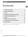
Contents
Contents
Declarations of conformity can be found online at www.wika.com.
1. General information 4
2. Design and function 5
3. Safety 6
4. Transport, packaging and storage 11
5. Commissioning, operation 11
6. Faults 15
7. Maintenance and cleaning 16
8. Dismounting, return and disposal 17
9. Specications 18

EN
017461.04 08/2017 EN/DE
4 Operating instructions level sensor, model FLR
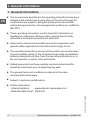
1. General information
■
The level sensors described in the operating instructions have been
designed and manufactured using state-of-the-art technology. All
components are subject to stringent quality and environmental
criteria during production. Our management systems are certied to
ISO 9001.
■
These operating instructions contain important information on
handling the instrument. Working safely requires that all safety
instructions and work instructions are observed.
■
Observe the relevant local accident prevention regulations and
general safety regulations for the instrument’s range of use.
■
The operating instructions are part of the product and must be kept
in the immediate vicinity of the instrument and readily accessible to
skilled personnel at any time. Pass the operating instructions on to
the next operator or owner of the instrument.
■
Skilled personnel must have carefully read and understood the
operating instructions prior to beginning any work.
■
The general terms and conditions contained in the sales
documentation shall apply.
■
Subject to technical modications.
■
Further information:
- Internet address: www.wika.de / www.wika.com
- Relevant data sheet: LM 20.02
1. General information

≤ 30°
EN
Operating instructions level sensor, model FLR
017461.04 08/2017 EN/DE
5
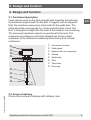
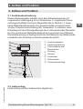
2. Design and function
2. Design and function
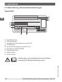
2.1 Functional description
Level sensors work on the oat principle with magnetic transmission.
A permanent magnet built into the oat triggers, with its magnetic
eld, the resistance measuring chain built into the guide tube. The
entire assembly corresponds to a 3-wire potentiometer circuit. The
oat changes its height with the level of the medium it is monitoring.
The measured resistance signal is proportional to the level. The
measurement voltage is very nely stepped due to the contact
separation of the resistance measuring chain and is thus virtually
continuous.
2.2 Scope of delivery
Cross-check scope of delivery with delivery note.
Connection housing
Cable gland
Spanner ats for screwing in
Sealing
Guide tube
Float
Teon disc
Float stop

EN
017461.04 08/2017 EN/DE
6 Operating instructions level sensor, model FLR
3. Safety
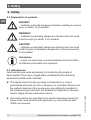
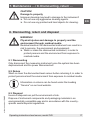
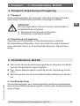
3.1 Explanation of symbols
DANGER!
... indicates a directly dangerous situation resulting in serious
injury or death, if not avoided.
WARNING!
... indicates a potentially dangerous situation that can result
in serious injury or death, if not avoided.
CAUTION!
... indicates a potentially dangerous situation that can result
in light injuries or damage to equipment or the environment,
if not avoided.
Information
... points out useful tips, recommendations and information
for ecient and trouble-free operation.
3.2 Intended use
Level sensors are used exclusively for monitoring the levels of
liquid media. The scope of application is defined by the technical
performance limits and materials.
■
The liquids must not have any large contamination or coarse
particulates and must not have a tendency to crystallise. Ensure that
the wetted materials of the level sensor are suciently resistant to
the medium being monitored. Not suitable for dispersions, abrasive
liquids, highly viscous media and colours.
■
This instrument is not permitted to be used in hazardous areas! For
these areas, level sensors with approval (e.g. in accordance with
ATEX) are required.
3. Safety

EN
Operating instructions level sensor, model FLR
017461.04 08/2017 EN/DE
7
■
The operating conditions specied in the operating instructions must
be observed.
■
Do not operate the instrument in the direct vicinity of ferromagnetic
environments (min. distance 50 mm).
■
Do not operate the instrument in the immediate vicinity of strong
electromagnetic elds or in the immediate vicinity of equipment that
can be aected by magnetic elds (min. clearance 1 m).
■
The level sensors must not be exposed to heavy mechanical strain
(impact, bending, vibration).
■
The technical specications contained in these operating instructions
must be observed. Improper handling or operation of the instrument
outside of its technical specications requires the instrument to be
taken out of service immediately and inspected by an authorised
WIKA service engineer.
The instrument has been designed and built solely for the intended
use described here, and may only be used accordingly.
The manufacturer shall not be liable for claims of any type based on
operation contrary to the intended use.
DANGER!
Work on vessels involves the danger of intoxication and
suocation. No work is allowed to be carried out unless by
taking suitable personal protective measures (e.g. respiratory
protection apparatus, protective outt etc.).
3. Safety

EN
017461.04 08/2017 EN/DE
8 Operating instructions level sensor, model FLR
3.3 Improper use
Improper use is dened as any application that exceeds the technical
performance limits or is not compatible with the materials.
WARNING!
Injuries through improper use
Improper use of the instrument can lead to hazardous
situations and injuries.
▶
Refrain from unauthorised modifications to the instrument.
▶
Do not use the instrument within hazardous areas.
Any use beyond or dierent to the intended use is considered as
improper use.
Do not use this instrument in safety or emergency stop devices.
3.4 Responsibility of the operator
The instrument is used in the industrial sector. The operator is therefore
responsible for legal obligations regarding safety at work.
The safety instructions within these operating instructions, as well as the
safety, accident prevention and environmental protection regulations for
the application area must be maintained.
To ensure safe working on the instrument, the operating company must
ensure the following:
■
The operating personnel are regularly instructed in all topics
regarding work safety, rst aid and environmental protection
and know the operating instructions and in particular, the safety
instructions contained therein.
■
The operating personnel have read the operating instructions and
taken note of the safety instructions contained therein.
■
The intended use for the application is complied with.
■
Following testing, improper use of the instrument is excluded.
3. Safety

EN
Operating instructions level sensor, model FLR
017461.04 08/2017 EN/DE
9
3.5 Personnelqualication
WARNING!
Riskofinjuryshouldqualicationbeinsucient
Improper handling can result in considerable injury and
damage to equipment.
▶
The activities described in these operating instructions
may only be carried out by skilled personnel who have the
qualifications described below.
Skilled personnel
Skilled personnel, authorised by the operator, are understood to be
personnel who, based on their technical training, knowledge of measu-
rement and control technology and on their experience and knowledge
of country-specic regulations, current standards and directives, are
capable of carrying out the work described and independently recognis-
ing potential hazards.
3.6 Personal protective equipment
The personal protective equipment is designed to protect the skilled
personnel from hazards that could impair their safety or health during
work. When carrying out the various tasks on and with the instrument,
the skilled personnel must wear personal protective equipment.
Follow the instructions displayed in the work area regarding
personal protective equipment!
The requisite personal protective equipment must be provided by the
operating company.
3. Safety

EN
017461.04 08/2017 EN/DE
10 Operating instructions level sensor, model FLR
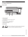
3.7 Labelling, safety marks
Product label
3. Safety
Type: AFVEN65/16/B1-VK5-L200/12-V44R
Ser. No.: 200012A1
BK
Art. No.: 210215
Tag No.:
IP65
max. AC 50 V / DC 75 V
Level Sensor FLR-SA
KSR KUEBLER
Niveau-Messtechnik AG
69439 Zwingenberg / Germany
manufactured for
BN
BU /
GY
Model, designation
Instrument code
Circuit diagram with colour coding per IEC 757
Switching power
Symbol of protection class per EN 61140
Ingress protection per IEC/EN 60529
Measuring point number
Article number
Serial number
Before mounting and commissioning the instrument,
ensure you read the operating instructions!

EN
Operating instructions level sensor, model FLR
017461.04 08/2017 EN/DE
11
4. Transport, packaging and storage
4.1 Transport
Check the level sensor for any damage that may have been caused by
transport. Obvious damage must be reported immediately.
CAUTION!
With improper transport, a high level of damage to property
can occur.
▶
Observe the symbols on the packaging.
▶
Handle packed goods with care.
4.2 Packaging and storage
Do not remove packaging until just before commissioning.
Keep the packaging as it will provide optimum protection during transport
(e.g. change in installation site, sending for repair).
5. Commissioning, operation
■
Observe all instructions given on the shipment packaging for
removing the transportation safety devices.
■
Remove the level sensor carefully from the packaging!
■
When unpacking, check all components for any external damage.
5.1 Functional check
Prior to installation, a functional test of the level sensor can be carried
out with a resistance measuring instrument and manual movement of the
oat.
4. Transport ... / 5. Commissioning, operation

EN
017461.04 08/2017 EN/DE
12 Operating instructions level sensor, model FLR
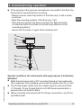
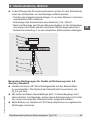
The following table describes the measurements and the expected
measured values for the movement of the oat, from bottom to top.
Resistance measurement
of the wire colours
Measured value
BK―BN(R1) Resistance value rises proportionally with the
position of the oat.
BU―BN(R2) Resistance value drops in inverse proportion
to the position of the oat.
BK―BU(Ri) Resistance value remains constant,
irrespective of the position of the oat.
WARNING!
Ensure that the functional check does not start any
unintended processes.
5.2 Mounting preparation
Ensure that the sealing faces of the vessel or level sensor are clean and
do not show any mechanical damage.
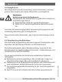
5.3 Mounting
■
Observe the torque values of screws specied in pipetting work.
■
In the selection of the mounting material (sealings, screws, washers
and nuts), take the process conditions into account. The suitability
of the sealing must be specied with regard to the medium and
its vapours. In addition, ensure it has corresponding corrosion
resistance.
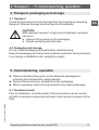
■
The level sensor is mounted to the vessel from the outside
■
The guide tube should not be inclined more than a maximum of
30° to the vertical.
■
Mount the level sensor correctly for the design of the process
connection.
5. Commissioning, operation

EN
Operating instructions level sensor, model FLR
017461.04 08/2017 EN/DE
13
■
If the opening of the process connection is too small for the oat, the
oat must be removed before mounting.
- Before removal, mark the position of the oat stop with a water-
proof pen
- Mark the mounting position of the oat (e.g. “Up”)
- After the level sensor has been mounted, the oat should be
re-attached within the inside of the tank (pay attention to the
mounting position!).
- Secure the oat stop again at the marked point.
Special conditions for instruments with approval per 3-A Sanitary
Standard
■
Weld the instrument with a 3/8" mounting thread on the media side.
The roughness of the welding seam must be smaller than R
a
0.4 µm.
■
The thread length visible from the outside should not be more than
1.5 threads. To any threads that do not full these requirements, a
special union nut must be tted.
■
When mounting instruments with Tri-Clamp connections, only t the
permitted seals.
≤ 30°
5. Commissioning, operation

EN
017461.04 08/2017 EN/DE
14 Operating instructions level sensor, model FLR
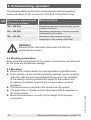
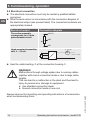
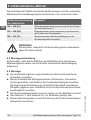
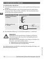
5.4 Electrical connection
■
The electrical connection must only be made by qualied skilled
personnel.
■
Wire the level sensor in accordance with the connection diagram of
the electrical output (see product label). The connection terminals are
appropriately marked.
Electrical output Connection diagram
The entire assembly
corresponds to a 3-wire
potentiometer circuit
Head-mounted transmitter
with 4 ... 20 mA
R
I
A
4 ... 20 mA
+
–
DC 12 ... 30 V
■
Seal the cable bushing at the connection housing .
WARNING!
Malfunctions through voltage spikes due to running cables
together with mains connection leads or due to large cable
lengths.
This can lead to a malfunction in the plant and thus lead to
injury to personnel or damage to equipment.
▶
Use shielded connection leads.
▶
Ground connection leads at one end.
Always observe the mounting and operating instructions of accessories
when commissioning them.
BU/GY
BN
BK
5. Commissioning, operation

EN
Operating instructions level sensor, model FLR
017461.04 08/2017 EN/DE
15
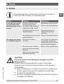
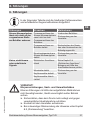
6. Faults
The following table contains the most frequent causes of
faults and the necessary countermeasures.
Faults Causes Measures
Level sensor cannot
be mounted at the
planned place on the
vessel
Process connection of
the level sensor does
not match to the process
connection of the vessel.
Modication of the vessel
Return to the manufacturer
Process connection at the
vessel defective
Rework the thread or
replace the screwed
coupling
Mounting thread at the level
sensor defective
Return to the manufacturer
No signal, non-linear
orundenedsignals
Electrical connection
incorrect
See chapter 5.4 “Electrical
connection”. Check the
assignment with the aid of
the connection diagram.
Measuring chain defective Return to the manufacturer
Head-mounted transmitter
defective
Head-mounted transmitter
adjusted incorrectly
CAUTION!
Physical injuries and damage to property and the
environment
If faults cannot be eliminated by means of the listed
measures, the instrument must be taken out of operation
immediately.
▶
Ensure that there is no longer any pressure present and
protect against being put into operation accidentally.
▶
Contact the manufacturer.
▶
If a return is needed, please follow the instructions given
in chapter 8.2 “Return”.
6. Faults

EN
017461.04 08/2017 EN/DE
16 Operating instructions level sensor, model FLR
7. Maintenance and cleaning
7.1 Maintenance
When used properly, the level sensors work maintenance-free. They
must be subjected to visual inspection within the context of regular
maintenance, however, and included in the vessel pressure test.
DANGER!
Work on containers involves the danger of intoxication and
suocation. No work is allowed to be carried out unless by
taking suitable personal protective measures (e.g. respiratory
protection apparatus, protective outt etc.).
Repairs must only be carried out by the manufacturer.
Perfect functioning of the level sensors can only be
guaranteed when original accessories and spare parts are
used.
7.2 Cleaning
CAUTION!
Physical injuries and damage to property and the
environment
Improper cleaning may lead to physical injuries and damage
to property and the environment. Residual media in the
dismounted instrument can result in a risk to persons, the
environment and equipment.
▶
Rinse or clean the removed instrument.
▶
Take sufficient precautionary measures.
1. Prior to cleaning, properly disconnect the instrument from the process
and the power supply.
2. Clean the instrument carefully with a moist cloth.
3. Electrical connections must not come into contact with moisture!
7. Maintenance and cleaning

EN
Operating instructions level sensor, model FLR
017461.04 08/2017 EN/DE
17
CAUTION!
Damage to property
Improper cleaning may lead to damage to the instrument!
▶
Do not use any aggressive cleaning agents.
▶
Do not use any pointed and hard objects for cleaning.
8. Dismounting, return and disposal
WARNING!
Physical injuries and damage to property and the
environment through residual media
Residual media in the dismounted instrument can result in a
risk to persons, the environment and equipment.
▶
Wash or clean the dismounted instrument, in order to
protect persons and the environment from exposure to
residual media.
8.1 Dismounting
Only disconnect the measuring instrument once the system has been
depressurised and the power disconnected!
8.2 Return
Wash or clean the dismounted level sensor before returning it, in order to
protect personnel and the environment from exposure to residual media.
Information on returns can be found under the heading
“Service” on our local website.
8.3 Disposal
Incorrect disposal can put the environment at risk.
Dispose of instrument components and packaging materials in an
environmentally compatible way and in accordance with the country-
specic waste disposal regulations.
7. Maintenance ... / 8. Dismounting, return ...

EN
017461.04 08/2017 EN/DE
18 Operating instructions level sensor, model FLR
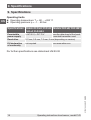
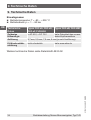
9. Specications
Operating limits
■
Operating temperature: T = -80 ... +200 °C
■
Operating pressure: p = -1 ... 80 bar
Specications Models FLR-xA, FLR-xE,
FLR-xF, FLR-HA3
Models FLR-xB, FLR-HB3
Permissible
power supply
< AC 50 V, < DC 75 V see the data sheet of the head-
mounted transmitter used
Resolution 2.7 mm, 5.5 mm, 7.5 mm, 9 mm (depending on version)
EU declaration
of conformity
not required see www.wika.com
For further specifications see data sheet LM 20.02
9.Specications

DE
Betriebsanleitung Niveau-Messwertgeber, Typ FLR
017461.04 08/2017 EN/DE
19
Inhalt
Inhalt
Konformitätserklärungen nden Sie online unter www.wika.de.
1. Allgemeines 20
2. Aufbau und Funktion 21
3. Sicherheit 22
4. Transport, Verpackung und Lagerung 27
5. Inbetriebnahme, Betrieb 27
6. Störungen 31
7. Wartung und Reinigung 32
8. Demontage, Rücksendung und Entsorgung 33
9. Technische Daten 34

DE
017461.04 08/2017 EN/DE
20 Betriebsanleitung Niveau-Messwertgeber, Typ FLR
1. Allgemeines
■
Die in der Betriebsanleitung beschriebenen Niveau-Messwertgeber
werden nach dem aktuellen Stand der Technik konstruiert und gefer-
tigt. Alle Komponenten unterliegen während der Fertigung strengen
Qualitäts- und Umweltkriterien. Unsere Managementsysteme sind
nach ISO 9001 zertiziert.
■
Diese Betriebsanleitung gibt wichtige Hinweise zum Umgang mit dem
Gerät. Voraussetzung für sicheres Arbeiten ist die Einhaltung aller
angegebenen Sicherheitshinweise und Handlungsanweisungen.
■
Die für den Einsatzbereich des Gerätes geltenden örtlichen Unfall-
verhütungsvorschriften und allgemeinen Sicherheitsbestimmungen
einhalten.
■
Die Betriebsanleitung ist Produktbestandteil und muss in unmittel-
barer Nähe des Gerätes für das Fachpersonal jederzeit zugänglich
aufbewahrt werden. Betriebsanleitung an nachfolgende Benutzer
oder Besitzer des Gerätes weitergeben.
■
Das Fachpersonal muss die Betriebsanleitung vor Beginn aller Arbei-
ten sorgfältig durchgelesen und verstanden haben.
■
Es gelten die allgemeinen Geschäftsbedingungen in den Verkaufs-
unterlagen.
■
Technische Änderungen vorbehalten.
■
Weitere Informationen:
- Internet-Adresse: www.wika.de / www.wika.com
- Zugehöriges Datenblatt: LM 20.02
1. Allgemeines
Seite wird geladen ...
Seite wird geladen ...
Seite wird geladen ...
Seite wird geladen ...
Seite wird geladen ...
Seite wird geladen ...
Seite wird geladen ...
Seite wird geladen ...
Seite wird geladen ...
Seite wird geladen ...
Seite wird geladen ...
Seite wird geladen ...
Seite wird geladen ...
Seite wird geladen ...
Seite wird geladen ...
Seite wird geladen ...
-
 1
1
-
 2
2
-
 3
3
-
 4
4
-
 5
5
-
 6
6
-
 7
7
-
 8
8
-
 9
9
-
 10
10
-
 11
11
-
 12
12
-
 13
13
-
 14
14
-
 15
15
-
 16
16
-
 17
17
-
 18
18
-
 19
19
-
 20
20
-
 21
21
-
 22
22
-
 23
23
-
 24
24
-
 25
25
-
 26
26
-
 27
27
-
 28
28
-
 29
29
-
 30
30
-
 31
31
-
 32
32
-
 33
33
-
 34
34
-
 35
35
-
 36
36


WIKA FLR-H tag:model:FLR-P tag:model:FLR-S Bedienungsanleitung
- Typ
- Bedienungsanleitung
- Dieses Handbuch eignet sich auch für
in anderen Sprachen
Verwandte Artikel
-
WIKA BNA Bedienungsanleitung
-
-
-
-
-
-
-
-
-