
DE
EN
Operating instructions
Betriebsanleitung
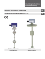
Magnetic oat switch, model FLS
Schwimmer-Magnetschalter, Typ FLS
Stainless steel version
mounting thread
Plastic version
ange connection

2
001888.04 05/2017 EN/DE
Operating instructions, magnetic oat switch, model FLS
DE
EN
Operating instructions model FLS Page 3 - 22
Betriebsanleitung Typ FLS Seite 23 - 42
© 06/2016 WIKA Alexander Wiegand SE & Co. KG
All rights reserved. / Alle Rechte vorbehalten.
WIKA
®
and KSR
®
are registered trademarks in various countries.
WIKA
®
and KSR
®
sind geschützte Marken in verschiedenen Ländern.
Prior to starting any work, read the operating instructions!
Keep for later use!
Vor Beginn aller Arbeiten Betriebsanleitung lesen!
Zum späteren Gebrauch aufbewahren!

EN
Operating instructions, magnetic oat switch, model FLS
001888.04 05/2017 EN/DE
3
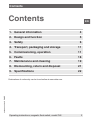
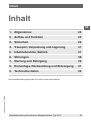
Contents
Contents
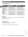
Declarations of conformity can be found online at www.wika.com.
1. General information 4
2. Design and function 5
3. Safety 6
4. Transport, packaging and storage 11
5. Commissioning, operation 11
6. Faults 18
7. Maintenance and cleaning 19
8. Dismounting, return and disposal 21
9. Specications 22

EN
001888.04 05/2017 EN/DE
4 Operating instructions, magnetic oat switch, model FLS
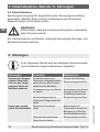
1. General information
■
The magnetic oat switches described in the operating instructions
have been designed and manufactured using state-of-the-art
technology. All components are subject to stringent quality and
environmental criteria during production. Our management systems
are certied to ISO 9001.
■
These operating instructions contain important information on
handling the instrument. Working safely requires that all safety
instructions and work instructions are observed.
■
Observe the relevant local accident prevention regulations and
general safety regulations for the instrument’s range of use.
■
The operating instructions are part of the product and must be kept
in the immediate vicinity of the instrument and readily accessible to
skilled personnel at any time. Pass the operating instructions on to
the next operator or owner of the instrument.
■
Skilled personnel must have carefully read and understood the
operating instructions prior to beginning any work.
■
The general terms and conditions contained in the sales
documentation shall apply.
■
Subject to technical modications.
■
Further information:
- Internet address: www.wika.de / www.wika.com
- Relevant data sheet: LM 30.01
Abbreviations, denitions
L-SP Level switch point
T-SP Temperature switch point
NO/NC Normally open/normally closed
CO Change-over
1. General information

≤ 30°
EN
Operating instructions, magnetic oat switch, model FLS
001888.04 05/2017 EN/DE
5
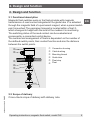
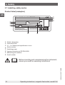
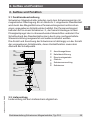
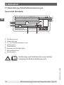
2. Design and function
2.1 Functional description
Magnetic oat switches work on the oat principle with magnetic
transmission. A reed contact integrated in the guide tube is actuated
through the magnetic eld of a permanent magnet, when a preset switch
point is reached. The permanent magnet is located within a oat ,
which changes its height with the level of the medium it is monitoring.
The switching status of the reed contact can be evaluated and
processed by a connected control device.
The number and arrangement of oats is dependent on the number of
the dened switch points, their contact function and also the distance
between the switch points.
Connection housing
Cable bushing
Mounting thread
Guide tube
Float stop
Float
2.2 Scope of delivery
Cross-check scope of delivery with delivery note.
2. Design and function

EN
001888.04 05/2017 EN/DE
6 Operating instructions, magnetic oat switch, model FLS
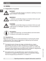
3. Safety
3.1 Explanation of symbols
DANGER!
... indicates a directly dangerous situation resulting in serious
injury or death, if not avoided.
WARNING!
... indicates a potentially dangerous situation that can result
in serious injury or death, if not avoided.
CAUTION!
... indicates a potentially dangerous situation that can result
in light injuries or damage to property or the environment, if
not avoided.
Information
... points out useful tips, recommendations and information
for ecient and trouble-free operation.
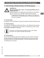
3.2 Intended use
Magnetic oat switches are used exclusively for monitoring the levels
of liquid media. The scope of application is dened by the technical
performance limits and materials.
■
The liquids must not have any large contamination or coarse
particulates and must not have a tendency to crystallise. Ensure
that the wetted materials of the magnetic oat switch are suciently
resistant to the medium being monitored. Not suitable for dispersions,
abrasive liquids, highly viscous media and colours.
■
This instrument is not permitted to be used in hazardous areas!
Excluded are magnetic oat switches which are marked as simple
electrical equipment per EN 60079-11 section 5.7.
3. Safety

EN
Operating instructions, magnetic oat switch, model FLS
001888.04 05/2017 EN/DE
7
■
The operating conditions specied in the operating instructions must
be observed.
■
Do not operate the instrument in the direct vicinity of ferromagnetic
environments (min. distance 50 mm).
■
Do not operate the instrument in the immediate vicinity of strong
electromagnetic elds or in the immediate vicinity of equipment that
can be aected by magnetic elds (min. clearance 1 m).
■
The magnetic oat switches must not be exposed to heavy
mechanical strain (impact, bending, vibration).
■
The technical specications contained in these operating instructions
must be observed. Improper handling or operation of the instrument
outside of its technical specications requires the instrument to be
taken out of service immediately and inspected by an authorised
WIKA service engineer.
The instrument has been designed and built solely for the intended use
described here, and may only be used accordingly.
The manufacturer shall not be liable for claims of any type based on
operation contrary to the intended use.
DANGER!
Work on vessels involves the danger of intoxication and
suocation. No work is allowed to be carried out unless by
taking suitable personal protective measures (e.g. respiratory
protection apparatus, protective outt etc.).
3. Safety

EN
001888.04 05/2017 EN/DE
8 Operating instructions, magnetic oat switch, model FLS
3.3 Improper use
Improper use is dened as any application that exceeds the technical
performance limits or is not compatible with the materials.
WARNING!
Injuries through improper use
Improper use of the instrument can lead to hazardous
situations and injuries.
▶
Refrain from unauthorised modifications to the instrument.
▶
Do not use the instrument within hazardous areas.
Any use beyond or dierent to the intended use is considered as
improper use.
Do not use this instrument in safety or emergency stop devices.
3.4 Responsibility of the operator
The instrument is used in the industrial sector. The operator is therefore
responsible for legal obligations regarding safety at work.
The safety instructions within these operating instructions, as well as the
safety, accident prevention and environmental protection regulations for
the application area must be maintained.
To ensure safe working on the instrument, the operating company must
ensure the following:
■
The operating personnel are regularly instructed in all topics
regarding work safety, rst aid and environmental protection
and know the operating instructions and in particular, the safety
instructions contained therein.
■
The operating personnel have read the operating instructions and
taken note of the safety instructions contained therein.
■
The intended use for the application is complied with.
■
Following testing, improper use of the instrument is excluded.
3. Safety

EN
Operating instructions, magnetic oat switch, model FLS
001888.04 05/2017 EN/DE
9
3.5 Personnel qualication
WARNING!
Risk of injury should qualication be insucient
Improper handling can result in considerable injury and
damage to equipment.
▶
The activities described in these operating instructions
may only be carried out by skilled personnel who have the
qualifications described below.
Skilled personnel
Skilled personnel, authorised by the operator, are understood to
be personnel who, based on their technical training, knowledge
of measurement and control technology and on their experience
and knowledge of country-specic regulations, current standards
and directives, are capable of carrying out the work described and
independently recognising potential hazards.
3.6 Personal protective equipment
The personal protective equipment is designed to protect the skilled
personnel from hazards that could impair their safety or health during
work. When carrying out the various tasks on and with the instrument, the
skilled personnel must wear personal protective equipment.
Follow the instructions displayed in the work area regarding
personal protective equipment!
The requisite personal protective equipment must be provided by the
operating company.
3. Safety

Type: ARV2"-VU-L1100/12-V52A
Ser. No.: 200012A1 Art. No.: 210215
L1: 250
L2: 350
L3: 690
L4:
L5:
Tag No.:
IP65
max. AC/DC 250 V
Magnetic float switch FLS-SA
KSR KUEBLER
Niveau-Messtechnik AG
69439 Zwingenberg / Germany
manufactured for
EN
001888.04 05/2017 EN/DE
10 Operating instructions, magnetic oat switch, model FLS
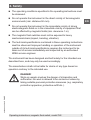
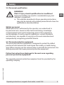
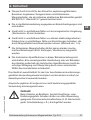
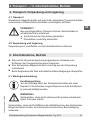
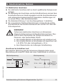
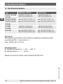
3.7 Labelling, safety marks
Product label (examples)
Model, designation
Instrument code
L1 ... Ln: Switch point specication in mm
Article number
Switching power
Ingress protection per IEC/EN 60529
Measuring point number
Serial number
Before mounting and commissioning the instrument,
ensure you read the operating instructions!
3. Safety

EN
Operating instructions, magnetic oat switch, model FLS
001888.04 05/2017 EN/DE
11
4. Transport, packaging and storage
4.1 Transport
Check the magnetic oat switch for any damage that may have been
caused by transport. Obvious damage must be reported immediately.
CAUTION!
With improper transport, a high level of damage to property
can occur.
▶
Observe the symbols on the packaging
▶
Handle packed goods with care
4.2 Packaging and storage
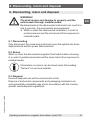
Do not remove packaging until just before commissioning.
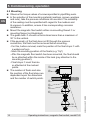
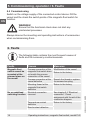
5. Commissioning, operation
■
Observe all instructions given on the shipment packaging for
removing the transportation safety devices.
■
Remove the magnetic oat switch carefully from the packaging!
■
When unpacking, check all components for any external damage.
5.1 Mounting preparation
Functional check
Before mounting, the oat switch can be connected as
described in chapter 5.3 and the switch points can be
operated manually.
WARNING!
Ensure that the functional check does not start any
unintended processes.
Ensure that the sealing faces of the vessel or magnetic oat switch are
clean and do not show any mechanical damage.
4. Transport ... / 5. Commissioning, operation

≤ 30°
EN
001888.04 05/2017 EN/DE
12 Operating instructions, magnetic oat switch, model FLS
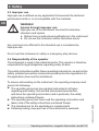
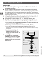
5.2 Mounting
■
Observe the torque values of screws specied in pipetting work.
■
In the selection of the mounting material (sealings, screws, washers
and nuts), take the process conditions into account. The suitability
of the sealing must be specied with regard to the medium and
its vapours. In addition, ensure it has corresponding corrosion
resistance.
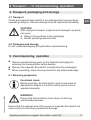
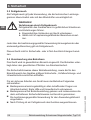
■
Mount the magnetic oat switch either via mounting thread or
mounting ange (not illustrated).
■
The guide tube should not be inclined more than a maximum of
30° to the vertical.
■
If the geometry of the oat does not t through the process
connection, the oat must be removed before mounting.
- For this, before removal, mark the position of the oat stops with
a waterproof pen
- Mark the mounting position of the oats (e.g. “Up”)
- After the magnetic oat switch has been mounted, the oat should
be re-attached within the inside of the tank (pay attention to the
mounting position!).
- Float stops must then be
re-attached at the marked
points.
■
The number of oats and also
the position of the oat stops are
dependent upon the dimension
and the number of switch points.
5. Commissioning, operation

EN
Operating instructions, magnetic oat switch, model FLS
001888.04 05/2017 EN/DE
13
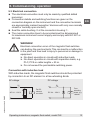
5.3 Electrical connection
■
The electrical connection must only be made by qualied skilled
personnel.
■
Connection details and switching functions are given on the
connection diagram on the instrument and the connection terminals
are appropriately marked (exception: Versions with only one normally
closed or normally open contact).
■
Seal the cable bushing at the connection housing .
■
The mains connection lines to be provided must be dimensioned
for maximum instrument current supply and comply with IEC 227 or
IEC 245.
WARNING!
Electrical connection errors of the magnetic oat switches
can destroy the reed contacts. This can lead to a malfunction
in the plant and thus lead to injury to personnel or damage to
equipment.
▶
No direct operation in circuits with inductive loads.
▶
No direct operation in circuits with capacitive loads, e.g.
PLC, PCS or cable lengths > 50 m.
▶
Do not exceed the permissible switching power.
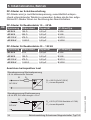
Connection with inductive load
With inductive loads, the magnetic float switches should be protected
by connection to an RC element or a free-wheeling diode.
For RC
element
see table
S1
AC 24 ... 230 V
R
C
S1
DC 24 ... 250 V
+
–
AC voltage DC voltage
Free-
wheeling
diode, e.g.
1N4007
5. Commissioning, operation

EN
001888.04 05/2017 EN/DE
14 Operating instructions, magnetic oat switch, model FLS
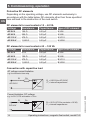
Protective RC elements
Depending on the operating voltage, use RC elements exclusively in
accordance with the table below. RC elements other than those specied
here will lead to the destruction of the reed switch.
RC elements for reed contacts 10 ... 40 VA
Voltage Resistance Capacitance Type of RC element
AC 24 V 100 Ω 0.33 μF A 3/24
AC 48 V 220 Ω 0.33 μF A 3/48
AC 115 V 470 Ω 0.33 μF A 3/115
AC 230 V 1,500 Ω 0.33 μF A 3/230
RC elements for reed contacts 40 ... 100 VA
Voltage Resistance Capacitance Type of RC element
AC 24 V 47 Ω 0.33 μF B 3/24
AC 48 V 100 Ω 0.33 μF B 3/48
AC 115 V 470 Ω 0.33 μF B 3/115
AC 230 V 1,000 Ω 0.33 μF B 3/230
Connection with capacitive load
R
S
= 220 Ω (for AC 230 V)
C₁ = internal capacitance
S1 R
S
+
–
C
1
AC 230 V
AC voltage current limitation
e.g. for electronic time relay
Relay
R
S
= 22 Ω (47 Ω for contacts ≤ 10 VA)
C₁ = internal capacitance
S1 R
S
+
–
C
1
DC 24 V
Current limitation, DC voltage
e.g. for PLC, PCS and cables > 50 m
PLC
5. Commissioning, operation

EN
Operating instructions, magnetic oat switch, model FLS
001888.04 05/2017 EN/DE
15
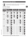
To increase the service life of the contacts, we recommend
operation with a contact protection relay.
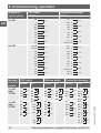
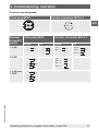
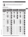
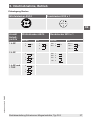
Connection diagrams
Colour coding per IEC 757
Number
of switch
points
PVC cable Silicone cable Connection housing
NO/NC CO NO/NC CO NO/NC CO
1 L-SP
GY
L1
BK
GY
L1
BN
BK
GY
L1
BK
GY
L1BN
BK
GY 1
L1
BN 2
GY 1
L1BN 2
BK 3
2 L-SP
BK
L1
BK
BN
L2
GY
YE
L1
GN
BK
BU
L2
PK
GY
BK
L1
BK
BN
L2
GY
YE
L1GN
BK
BU
L2RD
WH
BK 1
L1
BK 2
BN 3
L2
GY 4
YE 1
L1GN 2
BN 3
GY 4
L2RD 5
WH 6
3 L-SP
GN
L1
BN
YE
L2
GY
PK
L3
BU
BU-RD
L1
RD
WH
YE
L2
GN
BN
BU
L3
PK
GY
GN
L1
BN
YE
L2
GY
PK
L3
BU
-
BN 1
L1
WH 2
YE 3
L2
GN 4
GY 5
L3
RD 6
WH 1
L1BK 2
OG 3
YE 4
L2GN 5
BN 6
BU 7
L3PK 8
GY 9
4 L-SP
RD
L1
WH
GN
L2
BN
YE
L3
GY
PK
L4
BU
GY-RD
L1
BK
VT
BU-RD
L2
RD
WH
YE
L3
GN
BN
BU
L4
PK
GY
- -
RD 1
L1
WH 2
GN 3
L2
BN 4
YE 5
L3
GY 6
PK 7
L4
BU 8
WH
1
L1
BK
2
OG
3
YE
4
L2
GN
5
BN
6
BU
7
L3
PK
8
GY
9
RD
10
L4
VT
11
CLEAR 12
5. Commissioning, operation

EN
001888.04 05/2017 EN/DE
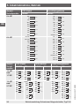
16 Operating instructions, magnetic oat switch, model FLS
Number of
switch points
PVC cable Connection housing
NO/NC NO/NC
5 L-SP
BK
L1
VI
RD
L2
WH
GN
L3
BN
YE
L4
GY
PK
L5
BU
RD 1
L1
WH 2
GN 3
L2
BN 4
YE 5
L3
GY 6
PK 7
L4
BU 8
VT 9
L5
CLEAR 10
6 L-SP
GY-RD
L1
BU-RD
BK
L2
VT
RD
L3
WH
GN
L4
BN
YE
L5
GY
PK
L6
BU
RD 1
L1
WH 2
GN 3
L2
BN 4
YE 5
L3
GY 6
PK 7
L4
BU 8
VT 9
L5
CLEAR 10
BK 11
L6
OG 12
Number
of switch
points
PVC cable Silicone cable Connection housing
NO/NC CO NO/NC CO NO/NC CO
1 L-SP
and
1 T-SP
BK
L1
BK
BN
ϑ
GY
GY
L1RD
WH
BN
ϑ
GN
BK
L1
BK
BN
ϑ
GY
GY
L1RD
WH
BN
ϑ
GN
BK 1
L1
BK 2
BN 3
ϑ
GY 4
GY 1
L1RD 2
WH 3
BN 4
ϑ
GN 5
1 L-SP
and
2 T-SP
GN
L1
BN
YE
ϑ
55°C
GY
PK
ϑ
75°C
BU
BU-RD
L1
RD
WH
YE
ϑ
55°C
GN
ϑ
75°C
PK
GY
BN
L1
WH
YE
ϑ
55°C
GN
BU
ϑ
75°C
RD
-
BN 1
L1
WH 2
YE 3
ϑ
55°C
GN 4
GY 5
ϑ
75°C
RD 6
WH 1
L1BK 2
OG 3
YE 4
ϑ
55°C
GN 5
BN 6
BU 7
ϑ
75°C
PK 8
GY 9
5. Commissioning, operation

EN
Operating instructions, magnetic oat switch, model FLS
001888.04 05/2017 EN/DE
17
Connector pin assignment
Cube plug ASC4 Circular connector M12 x 1
1
2
3
Number
of switch
points
Cube plug ASC4 Circular connector M12 x 1
NO/NC CO NO/NC CO
1 L-SP
1
L1
2
1
L13
2
BN 1
L1
WH 2
WH 2
L1BN 1
BK 4
2 L-SP
2
L1
1
L2
3
-
BN 1
L1
WH 2
BU 3
L2
BK 4
-
1 L-SP and
1 T-SP
2
L1
1
ϑ
3
-
5. Commissioning, operation

EN
001888.04 05/2017 EN/DE
18 Operating instructions, magnetic oat switch, model FLS
5.4 Commissioning
Switch on the voltage supply of the connected control device. Fill the
vessel and the check the switch points of the magnetic oat switch for
function.
WARNING!
Ensure that the functional check does not start any
unintended processes.
Always observe the mounting and operating instructions of accessories
when commissioning them.
6. Faults
The following table contains the most frequent causes of
faults and the necessary countermeasures.
Faults Causes Measures
Magnetic oat
switch cannot be
mounted at the
planned place on
the vessel
Process connection of the
magnetic oat switch does
not match the process
connection of the vessel.
Modication of the vessel
Return to the factory
Process connection at the
vessel defective
Rework the thread or replace
the screwed coupling
Mounting thread at the
magnetic oat switch
defective
Return to the factory
No or undened
switching function
Electrical connection
incorrect
See chapter 5.3 “Electrical
connection”. Check
assignment with the aid of the
connection diagram.
Temperature contact
defective
Return to the factory
Reed contact defective
5. Commissioning, operation / 6. Faults

EN
Operating instructions, magnetic oat switch, model FLS
001888.04 05/2017 EN/DE
19
CAUTION!
Physical injuries and damage to property and the
environment
If faults cannot be eliminated by means of the listed
measures, the instrument must be taken out of operation
immediately.
▶
Ensure that there is no longer any pressure present and
protect against being put into operation accidentally.
▶
Contact the manufacturer.
▶
If a return is needed, please follow the instructions given
in chapter 8.2 “Return”.
7. Maintenance and cleaning
7.1 Maintenance
When used properly, the magnetic oat switches work maintenance-free.
They must be subjected to visual inspection within the context of regular
maintenance, however, and included in the vessel pressure test.
DANGER!
Work on vessels involves the danger of intoxication and
suocation. No work is allowed to be carried out unless by
taking suitable personal protective measures (e.g. respiratory
protection apparatus, protective outt etc.).
Repairs must only be carried out by the manufacturer.
Perfect functioning of the magnetic oat switches can only
be guaranteed when original accessories and spare parts
are used.
6. Faults / 7. Maintenance and cleaning

EN
001888.04 05/2017 EN/DE
20 Operating instructions, magnetic oat switch, model FLS
7.2 Cleaning
CAUTION!
Physical injuries and damage to property and the
environment
Improper cleaning may lead to physical injuries and damage
to property and the environment. Residual media in the
dismounted instrument can result in a risk to persons, the
environment and equipment.
▶
Rinse or clean the removed instrument.
▶
Sufficient precautionary measures must be taken.
1. Prior to cleaning, properly disconnect the instrument from the process
and the power supply.
2. Clean the instrument carefully with a moist cloth.
3. Electrical connections must not come into contact with moisture!
CAUTION!
Damage to property
Improper cleaning may lead to damage to the instrument!
▶
Do not use any aggressive cleaning agents.
▶
Do not use any pointed and hard objects for cleaning.
7. Maintenance and cleaning
Seite wird geladen ...
Seite wird geladen ...
Seite wird geladen ...
Seite wird geladen ...
Seite wird geladen ...
Seite wird geladen ...
Seite wird geladen ...
Seite wird geladen ...
Seite wird geladen ...
Seite wird geladen ...
Seite wird geladen ...
Seite wird geladen ...
Seite wird geladen ...
Seite wird geladen ...
Seite wird geladen ...
Seite wird geladen ...
Seite wird geladen ...
Seite wird geladen ...
Seite wird geladen ...
Seite wird geladen ...
Seite wird geladen ...
Seite wird geladen ...
Seite wird geladen ...
Seite wird geladen ...
-
 1
1
-
 2
2
-
 3
3
-
 4
4
-
 5
5
-
 6
6
-
 7
7
-
 8
8
-
 9
9
-
 10
10
-
 11
11
-
 12
12
-
 13
13
-
 14
14
-
 15
15
-
 16
16
-
 17
17
-
 18
18
-
 19
19
-
 20
20
-
 21
21
-
 22
22
-
 23
23
-
 24
24
-
 25
25
-
 26
26
-
 27
27
-
 28
28
-
 29
29
-
 30
30
-
 31
31
-
 32
32
-
 33
33
-
 34
34
-
 35
35
-
 36
36
-
 37
37
-
 38
38
-
 39
39
-
 40
40
-
 41
41
-
 42
42
-
 43
43
-
 44
44


in anderen Sprachen
- English: WIKA FLS Operating instructions
Verwandte Artikel
-
WIKA MSA Bedienungsanleitung
-
-
-
-
-
-
-
-
-