SICK WTB8 Photoelectric proximity sensor Bedienungsanleitung
- Typ
- Bedienungsanleitung

English
Photoelectric proximity sensor
Operating instructions
Safety notes
• Read the operating instructions before commissioning.
• Connection, mounting, and setting may only be performed by trained
specialists.
• Not a safety component in accordance with the EU Machinery Directive.
• UL: Only for use in applications in accordance with NFPA 79. Adapters
listed by UL with connection cables are available. Enclosure type 1.
• When commissioning, protect the device from moisture and
contamination.
• These operating instructions contain information required during the
life cycle of the sensor.
Correct use
The WTB8 is an opto-electronic photoelectric proximity sensor (referred to
as “sensor” in the following) for the optical, non-contact detection of ob-
jects, animals, and persons. If the product is used for any other purpose or
modied in any way, any warranty claim against SICK AG shall become void.
Photoelectric proximity sensor with background suppression.
Commissioning
1
Check the application conditions: Adjust the sensing range and distance
to the object or background and the remission capability of the object
according to the corresponding diagram [H] (x = sensing range,
y = transition range between the set sensing range and suppression
of the background as a % of the sensing range (object remission /
background remission). Remission: 6 % = black, 18 % = gray,
90 % = white (referring to standard white as per DIN 5033).
The minimum distance (= y) for background suppression can be
determined from diagram [H] as follows:
Example: x = 200 mm, y = 6 % => 6 % of 200 mm = 12 mm.
That is, the background is suppressed at a distance of > 212 mm from
the sensor.
2 Mount the sensor using a suitable mounting bracket (see the SICK
range of accessories).
Note the sensor's maximum permissible tightening torque of 0.6 Nm.
Note the preferred direction of the object relative to the sensor.
3 The sensors must be connected in a voltage-free state (U
B
= 0 V). The
information in the graphics [B] must be observed, depending on the
connection type:
– Male connector connection: pin assignment
– Cable: core color
Only apply voltage / switch on the power supply (U
B
> 0 V) once all
electrical connections have been completed. The green LED indicator
lights up on the sensor.
Explanations of the connection diagram (graphic B):
Switching output Q (according to graphic B):
WTB8-P (PNP: load -> M)
L = light switching
D = dark switching
4 Align the sensor with the object. Select the position so that the red
emitted light beam hits the center of the object. You must ensure that
the optical opening (front screen) of the sensor is completely clear [E].
We recommend making the adjustments using an object with a low
remission.
5 Sensor with potentiometer:
The sensing range is adjusted with the potentiometer (type: 4 rota-
tions). Clockwise rotation: sensing range increased; counterclockwise
rotation: sensing range reduced. We recommend placing the switching
state in the object, e. g., see graphic F. Once the sensing range has
been adjusted, the object is removed from the path of the beam, which
causes the background to be suppressed and the switching output to
change (see graphic C).
The sensor is adjusted and ready for operation. Refer to graphics C
and G to check the function. If the switching output fails to behave in
accordance with graphic C, check application conditions. See section
Fault diagnosis.
Fault diagnosis
Table I indicates which measures are to be taken if the sensor stops working.
Disassembly and disposal
The sensor must be disposed of according to the applicable country-specic
regulations. Eorts should be made during the disposal process to recycle
the constituent materials (particularly precious metals).
Maintenance
SICK sensors are maintenance-free.
We recommend doing the following regularly:
– Clean the external lens surfaces
– Check the screw connections and plug-in connections
No modications may be made to devices.
Subject to change without notice. Specied product properties and
technical data are not written guarantees.
Deutsch
Reexions-Lichttaster
Betriebsanleitung
Sicherheitshinweise
• Vor der Inbetriebnahme die Betriebsanleitung lesen.
• Anschluss, Montage und Einstellung nur durch Fachpersonal.
• Kein Sicherheitsbauteil gemäß EU-Maschinenrichtlinie.
• UL: Nur zur Verwendung in Anwendungen gemäß NFPA 79.
Von UL gelistete Adapter mit Anschlusskabeln sind verfügbar.
Enclosure type 1.
• Gerät bei Inbetriebnahme vor Feuchte und Verunreinigung schützen.
• Diese Betriebsanleitung enthält Informationen, die während des
Lebenszyklus des Sensors notwendig sind.
Bestimmungsgemäße Verwendung
Die WTB8 ist ein optoelektronischer Reexions-Lichttaster (im Folgenden
Sensor genannt) und wird zum optischen, berührungslosen Erfassen von
Sachen, Tieren und Personen eingesetzt. Bei jeder anderen Verwendung und
bei Veränderungen am Produkt verfällt jeglicher Gewährleistungsanspruch
gegenüber der SICK AG.
Reexionslichttaster mit Hintergrundausblendung.
Inbetriebnahme
1
Einsatzbedingungen prüfen: Schaltabstand und Distanz zum Objekt
bzw. Hintergrund sowie Remissionsvermögen des Objektes mit dem
zugehörigen Diagramm [vgl. H] abgleichen (x = Schaltabstand,
y = Übergangsbereich zwischen eingestelltem Schaltabstand und
Ausblendung des Hintergrundes in % des Schaltabstands (Remission
Objekt / Remission Hintergrund)). Remission: 6 % = schwarz,
18 % = grau, 90 % = weiß (bezogen auf Standardweiß nach DIN 5033).
Die minimale Distanz (= y) für die Hintergrundausblendung kann aus
dem Diagramm [vgl. H] wie folgt ermittelt werden:
Beispiel: x = 200 mm, y = 6 % => 6 % von 200 mm = 12 mm.
D. h. der Hintergrund wird ab einer Distanz von > 212 mm vom Sensor
ausgeblendet.
2 Den Sensor an einen geeigneten Befestigungswinkel montieren
(siehe SICK-Zubehör-Programm).
Maximal zulässiges Anzugsdrehmoment des Sensors von 0,6 Nm
beachten.
Vorzugsrichtung des Objektes zum Sensor beachten [vgl. A].
3 Anschluss der Sensoren muss spannungsfrei (U
B
= 0 V) erfolgen.
Je nach Anschlussart sind die Informationen in den Graken [vgl. B]
zu beachten:
– Steckeranschluss: Pinbelegung
– Leitung: Adernfarbe
Erst nach Anschluss aller elektrischen Verbindungen die Span-
nungsversorgung (U
B
> 0 V) anlegen bzw. einschalten. Am Sensor
leuchtet die grüne Anzeige-LED.
Erläuterungen zum Anschlussschema (Grak B):
Schaltausgang Q (gemäß Grak B):
WTB8-P (PNP: Last -> M)
L = hellschaltend
D = dunkelschaltend
4 Sensor auf Objekt ausrichten. Positionierung so wählen, dass der rote
Sendelichtstrahl in der Mitte des Objekts auftrit. Es ist darauf zu acht-
en, dass die optische Önung (Frontscheibe) des Sensors vollständig
frei ist [vgl. E]. Wir empfehlen, die Einstellung mit einem Objekt von
niedriger Remission vorzunehmen.
5 Sensor mit Potentiometer:
Mit dem Potentiometer (Art: 4 Umdrehungen) wird der Schaltabstand
eingestellt. Drehung nach rechts: Erhöhung des Schaltabstandes,
Drehung nach links: Verringerung des Schaltabstandes. Wir empfeh-
len, den Schaltabstand in das Objekt zu legen, z. B. siehe Grak F.
Nachdem der Schaltabstand eingestellt worden ist, das Objekt aus
dem Strahlengang entfernen, der Hintergrund wird dabei ausgeblendet
und der Schaltausgang ändert sich (siehe Grak C).
Sensor ist eingestellt und betriebsbereit. Zur Überprüfung der Funktion
Grak C und G heranziehen. Verhält sich der Schaltausgang nicht gemäß
Grak C, Einsatzbedingungen prüfen. Siehe Abschnitt Fehlerdiagnose.
Fehlerdiagnose
Tabelle I zeigt, welche Maßnahmen durchzuführen sind, wenn die Funktion
des Sensors nicht mehr gegeben ist.
Demontage und Entsorgung
Die Entsorgung des Sensors hat gemäß den länderspezisch anwendbaren
Vorschriften zu erfolgen. Für die enthaltenen Wertstoe (insbesondere
Edelmetalle) ist im Rahmen der Entsorgung eine Verwertung anzustreben.
Wartung
SICK-Sensoren sind wartungsfrei.
Wir empfehlen, in regelmäßigen Abständen
– die optischen Grenzächen zu reinigen
– Verschraubungen und Steckverbindungen zu überprüfen
Veränderungen an Geräten dürfen nicht vorgenommen werden.
Irrtümer und Änderungen vorbehalten. Angegebene Produkteigenschaften
und technische Daten stellen keine Garantieerklärung dar.
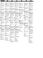
WTB8-x1xxx WTB8-x21xx / -x33xx WTB8-x22xx / -x34xx
Anzeige-LED / Fehlerbild /
LED indicator / fault pattern
Ursache /
Cause
Maßnahme /
Measures
grüne LED leuchtet nicht bzw. flackert /
green LED does not light up or flickers
Sensor ist noch betriebsbereit, aber die Betriebsbe-
dingungen sind nicht optimal (Funktionsreservefaktor
zwischen 0,9 und 1,1) /
Sensor is still ready for operation, but the operating
conditions are not ideal (operating reserve factor
between 0.9 and 1.1)
Betriebsbedingungen prüfen: Lichtstrahl (Lichtfleck)
vollständig auf das Objekt ausrichten / Reinigung der
optischen Flächen / Empfindlichkeit (Potentiometer)
neu einstellen / Schaltabstand überprüfen und ggf.
anpassen, siehe Grafik F. /
Check the operating conditions: Fully align the beam
of light (light spot) with the object. / Clean the optical
surfaces . / Readjust the sensitivity (potentiometer) /
Check sensing range and adjust if necessary;
see graphic F.
grüne LED leuchtet nicht /
green LED does not light up
keine Spannung oder Spannung unterhalb der
Grenzwerte /
no voltage or voltage below the limit values
Spannungsversorgung prüfen, den gesamten elektri-
schen Anschluss prüfen (Leitungen und Steckerver-
bindungen) /
Check the power supply, check all electrical
connections (cables and plug connections)
grüne LED leuchtet nicht /
green LED does not light up
Spannungsunterbrechungen /
Voltage interruptions
Sicherstellen einer stabilen Spannungsversorgung
ohne Unterbrechungen /
Ensure there is a stable power supply without
interruptions
grüne LED leuchtet nicht /
green LED does not light up
Sensor ist defekt /
Sensor is faulty
Wenn Spannungsversorgung in Ordnung ist, dann
Sensor austauschen /
If the power supply is OK, replace the sensor
gelbe LED leuchtet, kein Objekt im Strahlengang /
yellow LED lights up, no object in the path of the beam
Abstand zwischen Sensor und Hintergrund ist zu
gering /
Distance between the sensor and the background
is too short
Schaltabstand verringern, siehe Grafik F /
Reduce the sensing range, see graphic F
gelbe LED leuchtet nicht (gilt für hellschaltende Geräte),
bzw. gelbe LED leuchtet (gilt für dunkelschaltende
Geräte), Objekt ist im Strahlengang /
yellow LED does not light up (applies to light switching
devices) or yellow LED lights up (applies to dark
switching devices), object is in the path of the beam
Empfindlichkeit ist zu gering eingestellt oder Abstand
zwischen Sensor und Objekt ist zu groß /
Sensitivity is set too low or distance between the
sensor and the object is too long
Schaltabstand vergrößern, Abstand zwischen Sensor
und Hintergrund beachten, siehe Grafik F /
Increase the sensing range, take note of the distance
between the sensor and the background, see graphic F
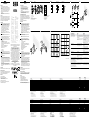
WTB8
11
(0.43)
8.1
(0.32)
18.8
(0.74)
8.3
(0.33)
20
(0.79)
3
(0.12)
20
(0.79)
3
(0.12)
25.4
(1.0)
31
(1.22)
2.8
(0.11)
25.4
(1.0)
31
(1.22)
2.8
(0.11)
17.5
(0.69)
1
2
3
45
6
6
6
6
11
(0.43)
8.1
(0.32)
18.8
(0.74)
8.3
(0.33)
18
(0.71)
1
2
3
45
|1| Standard dir
ection
|2| Cent
er of optical axis
|3| Connection
|4| LED indicat
or orange: switching output active
|5| LED indicat
or green: stability indicator
|6| Threaded mounting hole M3
8
7
45
LD
|4| LED indicator orange: switching output activ
e
|5| LED indicator green: stability indicator
|7| Sensing range adjustment
|8| Light / dark rotary switch:
L = light switching
D = dark switching
90 % / 90 %
6 % / 90 %
18 % / 90 %
020
(0.79)
40
(1.57)
60
(2.36)
80
(3.15)
100
(3.94)
5
4
3
2
1
0
1
2
3
Distance in mm (inch)
WTB8-xxx3x WTB8-xxx1x
Distanza di commutazione Distancia de conmutación
开关距离 最大検出範囲
Расстояние срабатывания
40 ... 300 mm 20 ... 100 mm
Distanza max. di commutazione Distancia de conmutación max.
最大开关距离 最大検出範囲
Расстояние срабатывания, макс.
30 ... 300 mm
1)
5 ... 100 mm
1)
Diametro punto luminoso / distanza Diámetro del punto luminoso / distancia 光斑直径 / 距离 光点のスポット径 / 距離 Диаметр светового пятна / расстояние
20 mm / 300 mm 6 mm / 100 mm
Tensione di alimentazione U
B
Tensión de alimentación U
B
供电电压 U
B
供給電圧 U
B
Напряжение питания U
B
DC 10 ... 30 V
2)
DC 10 ... 30 V
2)
Corrente di uscita I
max.
Intensidad de salida I
max.
输出电流 I
max.
出力電流 I
max.
Выходной ток I
макс.
100 mA 100 mA
Sequenza di commutazione max. Secuencia de conmutación max.
最大开关操作顺序 最大スイッチング周波数
Частота срабатывания
1,000 / s
3)
1,000 / s
3)
Tempo di reazione Tiempo de respuesta
响应时间 応答時間
Время отклика
0.5 ms
4)
0.5 ms
4)
Tipo di protezione Tipo de protección
防护类型 保護等級
Класс защиты
IP 67 IP 67
Classe di protezione Clase de protección
防护等级 保護クラス
Класс защиты
Commutazioni di protezione Circuitos de protección 保护电路 回路保護 Схемы защиты
A, B, D
5)
A, B, D
5)
Temperatura ambientale di funzionamento Temperatura ambiente de servicio
工作环境温度
周辺温度
(作動中) Диапазон рабочих температур
-25 ... + 55 °C -25 ... +55 °C
1)
Oggetto con il 90 % di remissione (riferito al bianco standard DIN 5033)
2)
Valori limite:
funzionamento in rete protetta da cortocircuito max. 8 A;
ondulazione residua max. 5 V
SS
3)
Con rapporto chiaro / scuro 1:1
4)
Durata segnale con carico ohmico
5)
A = U
B
-Allacciamenti protetti dall'inversione di polarità
B = entrate e uscite protette da polarità inversa
D = uscite protette da sovracorrente e da cortocircuito
1)
Material con un 90 % de reflexión (sobre el blanco estándar según DIN 5033)
2)
Valores límite:
funcionamiento en red protegida contra cortocircuitos max. 8 A;
ondulación residual max. 5 V
SS
3)
Con una relación claro / oscuro de 1:1
4)
Duración de la señal con carga óhmica
5)
A = U
B
protegidas contra polarización inversa
B = Entradas y salidas protegidas contra polarización incorrecta
D = Salidas a prueba de sobrecorriente y cortocircuitos
1)
具有 90 % 反射比的扫描对象(指 DIN 5033 规定的标准白)
2)
极限值:
在防短路电网中运行,最大 8 A;
最大余波 5 V
SS
3)
明暗比为 1:1
4)
信号传输时间(电阻负载时)
5)
A = U
B
接口(已采取反极性保护措施)
B = 具有反极性保护的输入端和输出端
D = 抗过载电流和抗短路输出端
1)
反射率 90 % の対象物(DIN 5033 に準拠した白色)
2)
限界値:
短絡保護の操作は最大 8 A;
残留リップルは最大 5 V
SS
3)
ライト / ダークの比率 1:1
4)
負荷のある信号経過時間
5)
A = U
B
接続は逆接保護
B = 入力および出力は逆接保護
D = 出力過電流および短絡保護
1)
Сканируемый объект – ремиссия 90 % (относительно стандартного белого по DIN 5033)
2)
Предельные значения:
эксплуатация в защищенной от короткого замыкания сети макс. 8 А;
остаточная волнистость макс. 5 B
SS
3)
Соотношение светлых и темных участков изображения 1:1
4)
Продолжительность сигнала при омической нагрузке
5)
A = U
B
-подключения с защитой от перепутывания полюсов
B = входы и выходы с защитой от перепутывания полюсов
D = выходы с защитой от тока перегрузки и короткого замыкания
WTB8-xxx3x WTB8-xxx1x
Sensing range Schaltabstand Portée Distância de comutação
40 ... 300 mm 20 ... 100 mm
Sensing range max. Schaltabstand max. Portée max. Distância de comutação max.
30 ... 300 mm
1)
5 ... 100 mm
1)
Light spot diameter / distance Lichtfleckdurchmesser / Entfernung Diamètre spot / distance Diâmetro do ponto de luz / distância
20 mm / 300 mm 6 mm / 100 mm
Supply voltage U
B
Versorgungsspannung U
B
Tension d'alimentation U
B
Tensão de alimentação U
B
DC 10 ... 30 V
2)
DC 10 ... 30 V
2)
Output current I
max.
Ausgangsstrom I
max.
Courant de sortie I
max.
Corrente de saída I
max.
100 mA 100 mA
Max. switching frequency Schaltfolge max. Commutation max. Sequência max. de comutação
1,000 / s
3)
1,000 / s
3)
Response time Ansprechzeit Temps de réponse Tempo de resposta
0.5 ms
4)
0.5 ms
4)
Enclosure rating Schutzart Indice de protection Tipo de proteção
IP 67 IP 67
Protection class Schutzklasse Classe de protection Classe de proteção
Circuit protection Schutzschaltungen Protections électriques Circuitos de proteção
A, B, D
5)
A, B, D
5)
Ambient operating temperature Betriebsumgebungstemperatur Température de service Temperatura ambiente de funcionamento
-25 ... + 55 °C -25 ... +55 °C
1)
Object with 90 % remission (based on standard white DIN 5033)
2)
Limit value:
operation in short-circuit protection mains max. 8 A;
residual ripple max. 5 V
SS
3)
With light / dark ratio 1:1
4)
Signal transit time with resistive load
5)
A = U
B
-connections reverse polarity protected
B = inputs and output reverse-polarity protected
D = outputs overcurrent and short-circuit protected
1)
Tastgut mit 90 % Remission (bezogen auf Standard-Weiß DIN 5033)
2)
Grenzwerte:
Betrieb im kurzschlussgeschützten Netz max. 8 A;
Restwelligkeit max. 5 V
SS
3)
Mit Hell- / Dunkelverhältnis 1:1
4)
Signallaufzeit bei ohmscher Last
5)
A = U
B
-Anschlüsse verpolsicher
B = Ein- und Ausgänge verpolsicher
D = Ausgänge überstrom- und kurzschlussfest
1)
Objet avec 90 % de réémission (par rapport au blanc standard selon DIN 5033)
2)
Valeurs limites :
fonctionnement sur réseau protégé contre les courts-circuits max. 8 A ;
ondulation résiduelle max. 5 V
CC
3)
Pour un rapport clair / sombre de 1:1
4)
Temps de propagation du signal sur charge ohmique
5)
A = raccordements U
B
protégés contre les inversions de polarité
B = entrées et sorties protégées contre les inversions de polarité
D = sorties protégées contre les courts-circuits et les surcharges
1)
Objeto a ser detectado com 90 % de luminância (com base no padrão branco DIN 5033)
2)
Valores limite:
funcionamento com rede à prova de curto-circuito max. 8 A;
ondulação residual max. 5 V
SS
3)
Com proporção sombra / luz 1:1
4)
Tempo de funcionamento do sinal com carga ôhmica
5)
A = conexões protegidas contra inversão de pólos U
B
B = Entradas e saídas protegidas contra polaridade inversa
D = Saídas protegidas contra sobrecorrente e curtocircuito
WTB8-xxx1x WTB8-xxx3x
Distance in mm (inch)
30
25
20
15
10
5
0
0 100
(3.94)
200
(7.87)
300
(11.81)
6 % / 90 %
18 % / 90 %
90 % / 90 %
1
2
3
WTB8-xxx1x
WTB8-xxx3x
+ (L+)
- (M)
Q
brn
blu
blk
+ (L+)
- (M)
Q
brn
blu
blk
1
3
4
+ (L+)
not connected
- (M)
brn
wht
blu
1
2
3
Q
blk
4
A B
C E
F G H I
More representatives and agencies at www.sick.com ∙ Subject to change
without notice ∙ The specied product features and technical data do not
represent any guarantee.
Weitere Niederlassungen nden Sie unter www.sick.com ∙ Irrtümer
und Änderungen vorbehalten ∙ Angegebene Produkteigenschaften und
technische Daten stellen keine Garantieerklärung dar.
Plus de représentations et d’agences à l’adresse www.sick.com ∙ Sujet à
modication sans préavis ∙ Les caractéristiques de produit et techniques
indiquées ne constituent pas de déclaration de garantie.
Para mais representantes e agências, consulte www.sick.com ∙ Alterações
poderão ser feitas sem prévio aviso ∙ As características do produto e os
dados técnicos apresentados não constituem declaração de garantia.
Altri rappresentanti ed agenzie si trovano su www.sick.com ∙ Contenuti
soggetti a modiche senza preavviso ∙ Le caratteristiche del prodotto e i
dati tecnici non rappresentano una dichiarazione di garanzia.
Más representantes y agencias en www.sick.com ∙ Sujeto a cambio sin
previo aviso ∙ Las características y los datos técnicos especicados no
constituyen ninguna declaración de garantía.
欲了解更多代表机构和代理商信息,请登录 www.sick.com ∙
如有更改, 不另行通知 ∙ 对所给出的产品特性和技术参数
的正确性不予保证。
その他の営業所はwww.sick.com よりご覧ください ・ 予告なしに変更され
ることがあります ・ 記載されている製品機能および技術データは保証を明
示するものではありません。
------------------------------------------------------------------------------------------------------------------------- -------------------------------------------------------------------------------------------------------------------------
BZ int49
Detailed addresses and further locations at www.sick.com
Australia
Phone +61 (3) 9457 0600
1800 33 48 02 –
tollfree
Austria
Phone +43 (0) 2236 62288-0
Belgium/Luxembourg
Phone +32 (0) 2 466 55 66
Brazil
Phone +55 11 3215-4900
Canada
Phone +1 905.771.1444
Czech Republic
Phone +420 234 719 500
Chile
Phone +56 (2) 2274 7430
China
Phone +86 20 2882 3600
Denmark
Phone +45 45 82 64 00
Finland
Phone +358-9-25 15 800
France
Phone +33 1 64 62 35 00
Germany
Phone +49 (0) 2 11 53 010
Greece
Phone +30 210 6825100
Hong Kong
Phone +852 2153 6300
Hungary
Phone +36 1 371 2680
India
Phone +91-22-6119 8900
Israel
Phone +972 97110 11
Italy
Phone +39 02 27 43 41
Japan
Phone +81 3 5309 2112
Malaysia
Phone +603-8080 7425
Mexico
Phone +52 (472) 748 9451
Netherlands
Phone +31 (0) 30 229 25 44
New Zealand
Phone +64 9 415 0459
0800 222 278 – tollfree
Norway
Phone +47 67 81 50 00
Poland
Phone +48 22 539 41 00
Romania
Phone +40 356-17 11 20
Russia
Phone +7 495 283 09 90
Singapore
Phone +65 6744 3732
Slovakia
Phone +421 482 901 201
Slovenia
Phone +386 591 78849
South Africa
Phone +27 10 060 0550
South Korea
Phone +82 2 786 6321/4
Spain
Phone +34 93 480 31 00
Sweden
Phone +46 10 110 10 00
Switzerland
Phone +41 41 619 29 39
Taiwan
Phone +886-2-2375-6288
Thailand
Phone +66 2 645 0009
Turkey
Phone +90 (216) 528 50 00
United Arab Emirates
Phone +971 (0) 4 88 65 878
United Kingdom
Phone +44 (0)17278 31121
USA
Phone +1 800.325.7425
Vietnam
Phone +65 6744 3732
SICK AG, Erwin-Sick-Strasse 1, D-79183 Waldkirch
2006/42/EG
NO
SAFETY
-------------------------------------------------------------------------------- 8017531.12HP 0719 COMAT -----------------------------------------------------------------------------
Seite wird geladen ...
-
 1
1
-
 2
2


SICK WTB8 Photoelectric proximity sensor Bedienungsanleitung
- Typ
- Bedienungsanleitung
in anderen Sprachen
- English: SICK WTB8 Photoelectric proximity sensor Operating instructions
- français: SICK WTB8 Photoelectric proximity sensor Mode d'emploi
- español: SICK WTB8 Photoelectric proximity sensor Instrucciones de operación
- italiano: SICK WTB8 Photoelectric proximity sensor Istruzioni per l'uso
- русский: SICK WTB8 Photoelectric proximity sensor Инструкция по эксплуатации
- português: SICK WTB8 Photoelectric proximity sensor Instruções de operação
- 日本語: SICK WTB8 Photoelectric proximity sensor 取扱説明書
Verwandte Artikel
-
SICK WTB8L Photoelectric proximity sensor Bedienungsanleitung
-
-
-
-
SICK WT100-2 energetic Bedienungsanleitung
-
-
-
-
-