
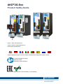
AKD
®
2G-Sxx
Product Safety Guide
Edition: -, Beta, December 2018
Valid for AKD2G, Hardware Revision A
Part Number 907-200024-99
English Deutsch Français Italiano Português Español Русский 中 国
Original language is English. All other content is translated from the genuine English content.
For safe and proper use, follow
these instructions.
Keep them for future reference.
Beta Drives: Approvals (CE, Functional Safety, UL) are pending.

Record of Document Revisions
Revision Remarks
...
Table with lifecycle information of this document see (➜ # 75)
Beta, 12/2018 Beta edition
Contents
Product Safety Guide English (➜ # 3) Product Safety Guide Português (➜ # 49)
Product Safety Guide Deutsch (➜ # 25) Product Safety Guide Español (➜ # 50)
Product Safety Guide Français (➜ # 47) Product Safety Guide Русский (➜ # 51)
Product Safety Guide Italiano (➜ # 48)
Product Safety Guide 中国
(➜ # 52)
Appendix/Electrical Data (➜ # 54) Appendix/Dimensions (➜ # 60)
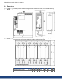
Appendix/Connection Overview (➜ # 61) Appendix/Approvals (➜ # 74)
Hardware Revision (HR)
AKD2G Firmware Workbench KAS IDE Remarks
A from 02-00-00-000 from 2.00.0.0000 from 3.01 Beta revision
Technical changes which improve the performance of the device may be made without prior notice!
This document is the intellectual property of Kollmorgen. All rights reserved. No part of this work may be reproduced
in any form (by photocopying, microfilm or any other method) or stored, processed, copied or distributed by electronic
means without the written permission of Kollmorgen.
Technische Änderungen zur Verbesserung der Leistung der Geräte ohne vorherige Ankündigung vorbehalten.
Dieses Dokument ist geistiges Eigentum von Kollmorgen. Alle Rechte vorbehalten. Kein Teil dieses Werkes darf in
irgendeiner Form (Fotokopie, Mikrofilm oder in einem anderenVerfahren) ohne schriftliche Genehmigung von Koll-
morgen reproduziert oder elektronisch verarbeitet, vervielfältigt oder verbreitet werden.
Sous réserve de modifications techniques apportés en vue d'amélioration des appareils!
Ce document est la propriété intellectuelle de Kollmorgen.Tous droits réservés. Sans autorisation écrite de
l'entreprise Kollmorgen, aucune partie de cet ouvrage n'a le droit d'être ni reproduite par des moyens quelconques
(impression, photocopie, microfilm ou autre procédure) ni traitée, polycopiée ou distribuée électronique.
Il produttore si riserva la facoltà di apportare modifiche tecniche volte al miglioramento degli apparecchi
Questo documento è la proprietà intellettuale di Kollmorgen. Tutti i diritti riservati. Nessuna parte del documento può
essere riprodotta in qualsiasi forma (fotocopia, microfilm o altro processo) senza l’approvazione scritta della ditta Koll-
morgen o rielaborata, riprodotta o diffusa mediante l’uso di sistemi elettronici.
Alterações técnicas que melhoram o desempenho do dispositivo podem ser feitos sem aviso prévio!
Este documento é uma propriedade intelectual da Kollmorgen. Todos os direitos reservados. Nenhuma parte deste
trabalho pode ser reproduzida sob qualquer forma (por fotocópia, microfilme ou qualquer outro método) ou
armazenado, processado, copiado ou distribuído por meios eletrônicos sem a permissão escrita da Kollmorgen.
Los cambios técnicos que mejoran el rendimiento del dispositivo pueden llevarse a cabo sin aviso previo.
Este documento es propiedad intelectual de Kollmorgen. Todos los derechos reservados. Ninguna parte de esta
obra, bajo concepto alguno, podrá reproducirse (por fotocopia, microfilm ni ningún otro método) ni almacenarse, pro-
cesarse, copiarse ni distribuirse por medios electrónicos sin el permiso por escrito de Kollmorgen.
Сохраняется право внесения технических изменений с целью усовершенствования приборов!
Настоящий документ является интеллектуальной собственностью Kollmorgen. Все права защищены.
Воспроизведение любой части данного издания в любой форме (фотокопия, микрофильм или иной метод) или
редактирование, размножение или распространение с помощью электронных систем без письменного
разрешения компании Kollmorgen запрещаются.
如有提升设备性能的技术变更,恕不另行通知!
本文档知识产权归 Kollmorgen 所有。版权所有。未经 Kollmorgen 书面许可,不得以任何形式( 利用影印、缩微胶
片或任何其他方法) 复制本文档的任何部分,也不得利用电子手段存储、处理、复制或分发本文档的任何部分。
2 Kollmorgen | kdn.kollmorgen.com | Beta, December 2018

1 English
1.1 General 4
1.1.1 Notes for the Printed Edition (paper version) 4
1.1.2 Symbols Used 5
1.1.3 Abbreviations Used 6
1.2 Product Safety 7
1.2.1 You should pay attention to this 7
1.2.2 Use as Directed 9
1.2.3 Prohibited Use 10
1.2.4 Warning note labels 11
1.3 Product life cycle handling 12
1.3.1 Transport 12
1.3.2 Packaging 12
1.3.3 Storage 12
1.3.4 Installation, setup and normal operation 13
1.3.5 Decommissioning 13
1.3.6 Maintenance and cleaning 13
1.3.7 Disassembly 13
1.3.8 System Repair 14
1.3.9 Disposal 14
1.4 Technical description and general data 15
1.4.1 Drive part number scheme 15
1.4.2 Package Supplied 16
1.4.3 Ambient Conditions, Ventilation, and Mounting Position 16
1.4.4 Electrical Data 17
1.4.5 Display, B1/2 push-buttons, S1/2 rotary switches 17
1.4.6 Fault and Warning Messages 18
1.5 Functional Safety 19
1.6 Mechanical Installation 20
1.7 Electrical Installation 21
1.8 Setup 22
1.9 Troubleshooting the AKD2G 24
AKD2G Product Safety Guide | 1 English
Kollmorgen | kdn.kollmorgen.com | Beta, December 2018 3

AKD2G Product Safety Guide | 1 English
1.1 General
This guide presents the relevant information for safe installation and setup of the AKD
®
2G
series of digital drives with functional safety support. This guide is valid for AKD
®
2G single
axis drive or dual axis drive with 110V to 240V or 240V to 480V mains voltage.
Ouput stages: 3 A, 6 A, 12 A rated current
Programmability options: Base drive or Position Indexer drive
Connectivity options: analog, CANopen, EtherCAT
I/O options: Extended I/O (X22), 2nd Feedback&EEO (X23)
Functional Safety options:
safety option 1 (SIL2 PLd) with STO or
safety option 2 (SIL3 PLe) with STO, SS1-t, SBC, SDB and SBT or
safety option 3 (SIL3 PLe) with STO, SS1-t, SS1-r, SS2, SLS, SSM, SSR, SDI, SLA,
SAR, SLI, SLP, SCA, SBC, SDB and SBT.
For full information refer to additional Kollmorgen documents for the AKD2G series of drives:
Installation Manual (PDF format):
This manual provides instructions for installation and drive setup.
Accessories Manual (PDF format):
It provides information for accessories like cables and regen resistors used with AKD2G.
Regional variants of this manual exist.
CAN-BUS Communication (PDF format):
Describes how to use your drive in CANopen applications.
EtherCAT Communication (PDF format):
Describes how to use your drive in EtherCAT applications.
WorkBench Online help (HTML5 format):
Describes how to use your drive in common applications. It also provides tips for max-
imizing your system performance with the AKD2G. The online help includes the Para-
meter and Command Reference Guide which provides information for the parameters and
commands used to program the AKD2G.
Beta Drives:
Approvals (CE, Functional Safety, UL) are pending.
All documents are in preliminary.
These documents can be found on the DVD in the drive package. All documents can be
downloaded from the Kollmorgen website www.kollmorgen.com.
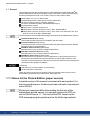
1.1.1 Notes for the Printed Edition (paper version)
A printed version of the manual is enclosed with each product. For
environmental reasons, the document was reduced in size and prin-
ted on DIN A5.
Should you experience difficulties reading the font size of the
scaled-down printed version, you can print and use the PDF ver-
sion in DIN A4 format 1:1. You can find the PDF version on the
DVD accompanying the product and on the Kollmorgen website.
4 Kollmorgen | kdn.kollmorgen.com | Beta, December 2018

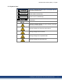
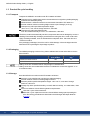
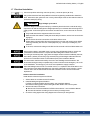
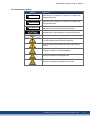
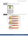
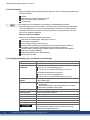
1.1.2 Symbols Used
Symbol Indication
DANGER
Indicates a hazardous situation which, if not avoided, will res-
ult in death or serious injury.
WARNING
Indicates a hazardous situation which, if not avoided, could
result in death or serious injury.
CAUTION
Indicates a hazardous situation which, if not avoided, could
result in minor or moderate injury.
Indicates situations which, if not avoided, could result in prop-
erty damage.
This symbol indicates important notes.
Warning of a danger (general). The type of danger is specified
by the text next to the symbol.
Warning of danger from electricity and its effects.
Warning of danger from hot surface.
Warning of danger from suspended loads.
Warning of danger from automatic start.
AKD2G Product Safety Guide | 1 English
Kollmorgen | kdn.kollmorgen.com | Beta, December 2018 5

AKD2G Product Safety Guide | 1 English
1.1.3 Abbreviations Used
Abbreviation Meaning
(➜ # 53) "see page 53" in this document
Ω Ohms
A#, AXIS# A# or AXIS# are placeholders for the axis number. Used with keywords or
signal names
AGND Analog ground
AMSL Above mean sea level
Axis Depends on context, either one AKD2G output stage or one load axis of
the full motion system.
CAT Category
CE Communité Européenne
COM Serial interface for a personal computer
DGND Digital ground
EEPROM Electrically erasable programmable memory
EEO Emulated Encoder Output
EMC Electromagnetic compatibility
EMF Electromagnetic force
F-SMA Fiber optic cable connector according to IEC 60874-2
FSoE Fail safe over EtherCAT
KAS Kollmorgen Automation Suite
KAS IDE Setup software (Kollmorgen Automation Suite Integrated Development
Environment)
KDN Kollmorgen Developer Network
LED Light-emitting diode
LSB Low significant byte (or bit)
MSB Main significant byte (or bit)
NI Zero pulse
OSSD Output Signal Switching Device
PC Personal computer
PE Protective earth
PELV Protective Extra Low Voltage
PLC Programmable logic control
PWM Pulse-width modulation
RAM Random access memory (volatile memory)
RBrake/RB Regen resistor (also called a brake resistor)
RBext External regen resistor
RBint Internal regen resistor
RCD Residual current device
RES Resolver
S1 Continuous operation
tbd To be discussed (in process)
VAC Volts, alternating current
VDC Volts, direct current
6 Kollmorgen | kdn.kollmorgen.com | Beta, December 2018

1.2 Product Safety
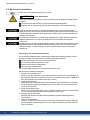
1.2.1 You should pay attention to this
Specialist staff required!
Only properly qualified personnel are permitted to perform such tasks as transport, install-
ation and setup. Qualified specialist staff are persons with expertise in transport, installation,
assembly, commissioning and operation of electrotechnical equipment.
Transport, storage, unpacking: only by personnel with knowledge of handling elec-
trostatically sensitive components.
Mechanical installation: only by personnel with mechanical expertise.
Electrical installation: only by personnel with electrotechnical expertise.
Basic tests / setup: only by personnel with expertise in electrical engineering and drive
technology.
The qualified personnel must know and observe ISO 12100 / IEC 60364 / IEC 60664 and
national accident prevention regulations.
Read the documentation!
Read the available documentation before installation and commissioning. Improper handling
of the devices can cause harm to people or damage to property. The operator of systems
using the drive system must ensure that all personnel who work with the drive read and under-
stand the manual before using the drive.
Check Hardware Revision!
Check the Hardware Revision Number of the product (see product label). This number is the
link between your product and the manual. The product Hardware Revision Number must
match the Hardware Revision Number on the cover page of the manual.
Pay attention to the technical data!
Adhere to the technical data and the specifications on connection conditions. If permissible
voltage values or current values are exceeded, the devices can be damaged. Unsuitable
motor or wrong wiring will damage the system components. Check the combination of drive
and motor. Compare the rated voltage and current of the units.
Perform a risk assessment!
The manufacturer of the machine must generate a risk assessment for the machine, and take
appropriate measures to ensure that unforeseen movements cannot cause injury or damage
to any person or property. Additional requirements on specialist staff may also result from the
risk assessment.
Automatic restart
The drive might restart automatically after power on, voltage dip or interruption of the supply
voltage, depending on the parameter setting. Risk of death or serious injury for humans work-
ing in the machine.
If the parameter AXIS#.ENDEFAULT is set to 1, then place a warning sign to the machine
(Warning: Automatic Restart at Power On) and ensure, that power on is not possible, while
humans are in a dangerous zone of the machine. In case of using an undervoltage protection
device, you must observe EN 60204-1:2006 chapter 7.5 .
AKD2G Product Safety Guide | 1 English
Kollmorgen | kdn.kollmorgen.com | Beta, December 2018 7

AKD2G Product Safety Guide | 1 English
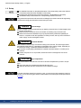
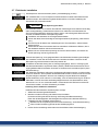
Observe electrostatically sensitive components!
The devices contain electrostatically sensitive components which may be damaged by incor-
rect handling. Electrostatically discharge your body before touching the device. Avoid con-
tact with highly insulating materials (artificial fabrics, plastic film etc.). Place the device on a
conductive surface.
Hot surface!
Drives may have hot surfaces during operation. The housing can reach temperatures above
80°C. Risk of minor burns! Measure the temperature, and wait until the housing has cooled
down below 40 °C before touching it.
Earthing!
It is vital that you ensure that the drive is safely earthed to the PE (protective earth) busbar in
the switch cabinet. Risk of electric shock. Without low-resistance earthing no personal pro-
tection can be guaranteed.
Leakage Current!
Since the leakage current to PE is more than 3.5 mA, in compliance with IEC61800-5-1 the
PE connection must either be doubled or a connecting cable with a cross-section >10 mm²
must be used. Deviating measures according to regional standards might be possible.
High voltages!
The equipment produces high electric voltages up to 900 V. Lethal danger exists at live parts
of the device. Do not open or touch the equipment during operation. Keep all covers and cab-
inet doors closed. Built-in protection measures such as insulation or shielding may not be
removed. Work on the electrical installation may only be performed by trained and qualified
personnel, in compliance with the regulations for safety at work, and only with switched off
mains supply, and secured against restart.
Never undo any electrical connections to the drive while it is live. There is a danger of elec-
trical arcing with damage to contacts and personal injury. Wait at least 5 minutes after dis-
connecting the drive from the main supply power before touching potentially live sections of
the equipment (such as contacts) or removing any connections.
Always measure the voltage in the DC bus link and wait until the voltage is below 50 V
before handling components.
Functional Safety!
Beta drives: Safety functionality is not approved nor certified. Do not use this functionality in
applications with functional safety request.
The assessment of the safety functions according to EN13849 or EN 62061 must finally be
done by the user.
Reinforced Insulation
Thermal sensors, motor holding brakes and feedback systems built into the connected motor
must have reinforced insulation (according to IEC61800-5-1) against system components
with power voltage, according to the required application test voltage. All Kollmorgen com-
ponents meet these requirements.
Never modify the drive!
It is not allowed to modify the drive hardware without permission by the manufacturer. Open-
ing the housing causes loss of warranty.
8 Kollmorgen | kdn.kollmorgen.com | Beta, December 2018

1.2.2 Use as Directed
The AKD2G drives are exclusively intended for driving suitable synchronous servomotors
with closed-loop control of torque, speed, and/or position.
AKD2G are components that are built into electrical plants or machines and can only be oper-
ated as integral components of these plants or machines. The manufacturer of the machine
used with a drive must generate a risk assessment for the machine. When the drives are built
into machines or plant, the drive must not be used until it has been established that the
machine or plant fulfills the requirements of the regional directives.
Cabinet and wiring
Drives must only be operated in a closed control cabinet suitable for the ambient conditions
(➜ # 16). Ventilation or cooling may be necessary to keep the temperature within the cabinet
below 40°C.
Use only copper conductors for wiring. The conductor cross-sections can be derived from the
standard IEC 60204 (alternatively for AWG cross-sections: NEC Table 310-16, 75°C
column).
Power supply
The drives can be supplied by 1, 2 or 3 phase industrial supply networks.
Drives in the AKD2G series can be supplied as follows:
AKD2G-Sxx-6Vxx:
1, 2 or 3 phase industrial supply networks (not more than 200 kA symmetrical rated cur-
rent at 120 V and 240 V).
AKD2G-Sxx-7Vxx:
3 phase industrial supply networks (not more than 200 kA symmetrical rated current at
240 V, 400 V and 480 V).
Connection to other voltage types of supply networks is possible with an additional isolating
transformer.
Repeated overvoltages between phases (L1, L2, L3) and the housing of the drive must not
exceed 1000 V peak. In accordance with IEC 61800, voltage spikes (< 50 µs) between
phases must not exceed 1000 V. Voltage spikes (<50 µs) between a phase and the housing
must not exceed 2000 V.
EMC filter measures for AKD2G-Sxx-6Vxx must be implemented by the user.
Motor voltage rating
The rated voltage of the motors must be at least as high as the DC bus link voltage divided
by √2 produced by the drive (U
nMotor
>=U
DC
/√2).
Functional Safety
Beta Drives: Safety functionality is neither approved nor certified yet. Do not use this func-
tionality in applications with functional safety request until further notice.
The network, to which the drive is connected, must be secured according to state-of-the-
art information technology security requirements.
The user IT specialists shall analyze whether further security requirements are applic-
able to ensure functional safety.
Review the chapter "Use as Directed" in the Functional Safety section before using safety
functionality.
AKD2G Product Safety Guide | 1 English
Kollmorgen | kdn.kollmorgen.com | Beta, December 2018 9

AKD2G Product Safety Guide | 1 English
1.2.3 Prohibited Use
Other use than that described in chapter “Use as directed” is not intended and can lead to per-
sonnel injuries and equipment damage. The drive may not be used with a machine that does
not comply with appropriate national directives or standards. The use of the drive in the fol-
lowing environments is also prohibited:
potentially explosive areas
environments with corrosive and/or electrically conductive acids, alkaline solutions, oils,
vapors, dusts
ships or offshore applications
The drive must not be connected directly to the Internet. If the network, to which the drive is
connected, is not secured according to state-of-the-art information technology, this could be
a functional safety risk.
10 Kollmorgen | kdn.kollmorgen.com | Beta, December 2018

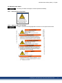
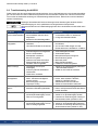
1.2.4 Warning note labels
If a warning note label is damaged, it must be replaced immediately.
1.2.4.1 Notes placed on the product
AKD2G
Wait 5 minutes
after removing power
before servicing.
1.2.4.2 Adhesive label in the package
To meet UL, place the multi-language label on the drive or on the panel near the drive.
AKD2G Product Safety Guide | 1 English
Kollmorgen | kdn.kollmorgen.com | Beta, December 2018 11

AKD2G Product Safety Guide | 1 English
1.3 Product life cycle handling
1.3.1 Transport
Transport the AKD2G in accordance with IEC 61800-2 as follows:
Transport only by qualified personnel in the manufacturer’s original recyclable packaging.
Avoid shocks while transporting.
Vibration/Shock: AKD2G is tested for environmental class 2M1 of IEC 60721-3-2.
Store at or below maximum stacking height 8 cartons (see "Storage" (➜ # 12))
Transport only within specified temperature ranges:
-25 to +70 °C, max. rate of change 20 K/hour, class 2K3.
Transport only within specified humidity:
max. 95% relative humidity at +40°C, no condensation, class 2K3.
The drives contain electrostatically sensitive components that can be damaged by incorrect
handling. Electrostatically discharge yourself before touching the drive. Avoid contact with
highly insulating materials, such as artificial fabrics and plastic films. Place the drive on a
conductive surface.
If the packaging is damaged, check the unit for visible damage. Inform the shipper and the
manufacturer of any damage to the package or product.
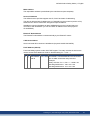
1.3.2 Packaging
The AKD2G packaging consists of recyclable cardboard with inserts and a label on the out-
side of the box.
Model Package
(mm) HxWxL
Total Weight
(kg)
AKD2G-Sxx-6V03 to 6V12 tbd 4.2
AKD2G-Sxx-7V03 to 7V12 tbd 4.3
Mating connectors are not included in the package of a standard drive.
Mating connectors are included when the drive is ordered with accessories (append “-A” to
the model number).
1.3.3 Storage
Store the AKD2G in accordance with IEC 61800-2 as follows:
Store only in the manufacturer’s original recyclable packaging.
Store at or below maximum stacking height 8 cartons.
Store only within specified temperature ranges: -25 to +55 °C, max.rate of change
20K/hour, class 1K4.
Storage only within specified humidity: 5 to 95% relative humidity, no condensation, class
1K3.
Store in accordance with the following duration requirements:
Less than 1 year: without restriction.
More than 1 year: capacitors must be re-formed before setting up and operating the
drive. Re-forming procedures are described in the Kollmorgen Developer Network
(Forming).
12 Kollmorgen | kdn.kollmorgen.com | Beta, December 2018

1.3.4 Installation, setup and normal operation
Installation and setup information are given in this Guide:
Mechanical installation (➜ # 20)
Electrical installation (➜ # 21)
Setup (➜ # 22)
Normal operation tested for environmental class 3K3 according to IEC 61800-2 (➜ # 16).
The manufacturer of the machine defines the necessary end user expertise based on the risk
assessment for the machine and describes the requirements for normal operation based on
the application.
1.3.5 Decommissioning
Only professional staff who are qualified in electrical engineering are allowed to decom-
mission parts of the system.
DANGER: Lethal Voltages!
There is a danger of serious personal injury or death by electrical shock or electrical arcing.
Switch off the main switch of the switchgear cabinet.
Secure the system against restarting.
Block the main switch.
Wait at least 5 minutes after disconnecting.
1.3.6 Maintenance and cleaning
The device does not require maintenance. Opening the device voids the warranty. The inside
of the unit can only be cleaned by the manufacturer.
Do not immerse or spray the device. Avoid that liquid enters the device.
To clean the device exterior:
1. Decommission the device (see chapter 1.3.5 "Decommissioning").
2. Casing: Clean with isopropanol or similar cleaning solution.
Caution : Highly Flammable! Risk of injury by explosion and fire.
Observe the safety notes given on the cleaning liquid package.
Wait at least 30 minutes after cleaning before putting the device back into operation.
3. Protective grill on fan: Clean with a dry brush.
1.3.7 Disassembly
Only professional staff who are qualified in electrical engineering are allowed to disassemble
parts of the system.
1. Decommission the device (see chapter 1.3.5 "Decommissioning").
2. Check temperature.
CAUTION: High Temperature! Risk of minor burns. During operation, the heat sink of
the drive may reach temperatures above 80°C (176°F). Before touching the device,
check the temperature and wait until it has cooled below 40°C (104°F).
3. Remove the connectors. Disconnect the potential earth connection last.
4. Demount: loosen the fastening screws. Remove the device.
AKD2G Product Safety Guide | 1 English
Kollmorgen | kdn.kollmorgen.com | Beta, December 2018 13

AKD2G Product Safety Guide | 1 English
1.3.8 System Repair
Only professional staff who are qualified in electrical engineering are allowed to exchange
parts of the drive system.
CAUTION: Automatic Start! During replacement work a combination of hazards and mul-
tiple episodes may occur.
Work on the electrical installation may only be performed by trained and qualified per-
sonnel, in compliance with the regulations for safety at work, and only with use of pre-
scribed personal safety equipment.
Exchange of the device
Only the manufacturer can repair the device. Opening the device voids the warranty.
1. Decommission the device (see chapter 1.3.5 "Decommissioning").
2. Demount the device (see chapter 1.3.7 "Disassembly").
3. Send the device to the manufacturer.
4. Install a new device as described in this manual.
5. Setup the system as described in this manual.
Exchange of other drive system parts
If parts of the drive system (for example cables) must be replaced, proceed as follows:
1. Decommission the device (see chapter 1.3.5 "Decommissioning").
2. Exchange the parts.
3. Check all connections for correct fastening.
4. Setup the system as described in this manual.
1.3.9 Disposal
To dispose the unit properly, contact a certified electronic scrap disposal merchant.
In accordance with the WEEE-2012/19/EC guideline and similar, the manufacturer accepts
returns of old devices and accessories for professional disposal. Transport costs are the
responsibility of the sender.
Contact Kollmorgen and clarify the logistics.
Send the devices in the original packaging to the manufacturer address:
North America South America
KOLLMORGEN
201 West Rock Road
Radford, VA 24141, USA
KOLLMORGEN
Avenida João Paulo Ablas, 2970
Jardim da Glória, Cotia – SP
CEP 06711-250, Brazil
Europe Asia
KOLLMORGEN Europe GmbH
Pempelfurtstr. 1
40880 Ratingen, Germany
KOLLMORGEN
Floor 4, Building 9, No. 518,
North Fuquan Road, Changning District,
Shanghai 200335, China
14 Kollmorgen | kdn.kollmorgen.com | Beta, December 2018

1.4 Technical description and general data
The AKD2G is a digital servo drive with extended functionality that is ideal for complex drive
tasks with functional safety requirements.
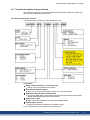
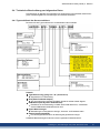
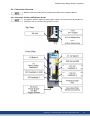
1.4.1 Drive part number scheme
Use the part number scheme for product identification only.
Accessories
Model number followed by "-A" (Accessories)
Mating connectors included in the package.
SFA (Smart Feedback Adapter)
SFA converts conventional feedback signals to a 2-wire serial signal.
SDB Module (Safe Dynamic Brake Module)
Required for SDB usage. When SDB is activated, the external Safe Dynamic Brake
Module (SDB-Module) shorts the motor terminals.
Hybrid motor cables
Motor cables with integrated power, brake and feedback leads.
External regen resistors
High power resistors for dissipation of generative energy.
For accessories refer to your regional Accessories Manual.
AKD2G Product Safety Guide | 1 English
Kollmorgen | kdn.kollmorgen.com | Beta, December 2018 15

AKD2G Product Safety Guide | 1 English
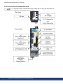
1.4.2 Package Supplied
When a standard drive from the AKD2G series is delivered, the following items are included
in the drive package:
AKD2G
Printed copy of AKD
®
2G Product Safety Guide .
DVD with WorkBench setup software .
Panel safety label
Mating connectors are not included in the package of a standard drive.
Mating connectors are included when the drive is ordered with accessories (append “-A” to
the model number). With the accessories option all connectors to match the drive variant are
included, excepting SubD (Feedback 3), RJ25 (CAN bus) and RJ45 (service and fieldbus
networks).
Accessories Sold Separately
Accessories must be ordered separately if required.
EMC filters for mains supply voltage, categories C2 or C3.
External regen resistor.
Connector kits
Hybrid cable. Assembled hybrid motor cables are available for all regions.
Motor cable. Assembled motor cables are available for all regions.
Feedback cable. Assembled feedback cables are available for all regions.
SFA (Smart Feedback Adapter) .
SDB Module (Safe Dynamic Brake Module).
Ethernet service cable.
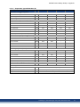
1.4.3 Ambient Conditions, Ventilation, and Mounting Position
Storage, Transport (➜ # 12)
Normal operation Environmental class 3K3 according to IEC 61800-2
Surrounding tem-
perature in operation
Internal regen resistor used:
0 to +40 °C under rated conditions
+40 to +60 °C with current derating 3 % per Kelvin
Internal regen resistor not used:
0 to +50 °C under rated conditions
+50 to +60 °C with current derating 2 % per Kelvin
Humidity in operation Relative humidity 5 to 85%, no condensation, IEC 61800-2 class
3K3
Site altitude Up to 1000 m above mean sea level (AMSL): no restriction
1,000 to 2,000 m AMSL: power derating 1.5%/100 m
Maximum altitude: 2000 m AMSL
Pollution level Pollution level 2 as per IEC 60664-1
Vibration Class 3M1 according to IEC 61800-2
Shock Class L according to IEC 61800-2
Drive protection IP 20 according to IEC 60529
Drive EMC immunity Increased immunity according to EN 61800-5-2
Mounting Vertical position, in a cabinet with protection of at least IP 54
Ventilation Built-in fan in all drive variants
The drive shuts down in case of excessively high temperature in
the control cabinet. Make sure sufficient forced ventilation is sup-
plied within the control cabinet.
16 Kollmorgen | kdn.kollmorgen.com | Beta, December 2018

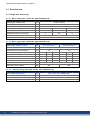
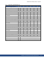
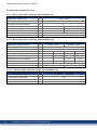
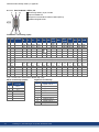
1.4.4 Electrical Data
Electrical data (➜ # 54)
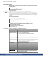
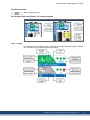
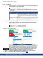
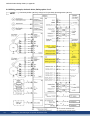
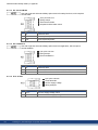
1.4.5 Display, B1/2 push-buttons, S1/2 rotary switches
AKD2G with Safety Option 1 AKD2G with Safety Option 2 or 3
1.4.5.1 Display
The LCD display offers several screens, which can be navigated by pushing the B1 or B2 but-
tons. Different colors visualize the current axis status.
AKD2G Product Safety Guide | 1 English
Kollmorgen | kdn.kollmorgen.com | Beta, December 2018 17

AKD2G Product Safety Guide | 1 English
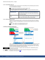
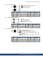
1.4.5.2 Push-buttons B1 / B2
A short button press invokes the action corresponding to the symbol directly above the but-
ton. On the dashboard for example,
a short press on B1 causes the menu system to appear, and
a short press on B2 causes a help screen to appear.
A long press (greater than 2 seconds) on B2 returns the display to the previous screen.
More B1/B2 functions Description
Boot from SD card Push both buttons during power up to boot with data from SD
card. Press the buttons first, then hold it down while turning on
the 24 V power supply.
Boot from flash fallback
image
Push both buttons during power up, without an SD card, to boot
from an on-board recovery image. Press the buttons first, then
hold it down while turning on the 24 V power supply.
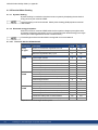
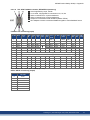
1.4.5.3 Rotary switches S1 / S2
AKD2G with functional safety option 2 or 3 offer two decimal rotary switches for setting the
Safe ID. The SafeID is calculated based on a fixed number plus an adder set with the rotary
switches.
Axis 1: 256 + adder 1 to 99, SafeID range 257 to 355
Axis 2: 512 + adder 1 to 99, SafeID range 513 to 611
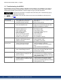
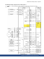
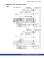
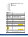
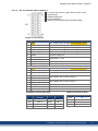
1.4.6 Fault and Warning Messages
Fault codes and Warning codes follow the same four digit code "G G X X", where GG is a two
digit group code, and XX is a two digit ID. The display on the front panel of the drive shows
the code of the fault or warning that occurred for the axis. Navigate with B1 / B2 to the Fault
screen to see a short description of the fault or warning.
Eliminate errors and faults in compliance with work safety rules. Troubleshooting only by
qualified and trained staff.
More information about fault messages, remedy and clearing faults can be found in the
WorkBench online help and in KDN.
18 Kollmorgen | kdn.kollmorgen.com | Beta, December 2018

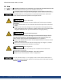
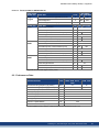
1.5 Functional Safety
Beta Drives: Functionality Safety of AKD2G is neither approved nor certified. Do not use
this functionality in applications with functional safety request.
There are three optional levels of Functional Safety implementation for AKD2G:
Option 1 (SIL2 PLd): STO, activation by safe I/O
Option 2 (SIL3 PLe): STO, SS1-t, SBC, SBT, SDB, activation by safe I/O or FSoE
Option 3 (SIL3 PLe): STO, SS1-t, SS1-r, SS2, SLS, SSM, SSR, SDI, SLA, SAR, SLI,
SLP, SCA, SBC, SBT, SDB, activation by safe I/O or FSoE
Resulting Functional Safety classification (SIL and/or PL level) must be calculated across
the drive system.
The safety properties given by Kollmorgen can be reached if the Kollmorgen components are
used. Refer to the matching AKD2G-S Installation Manual for full information on the installed
functional safety option.
Parameterizing of the safety functions shall be done by trained personnel only. The level of
experience shall beappropriate tothe complexity and safety integrity level of the drive sys-
tem.
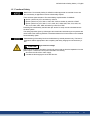
CAUTION
High electrical voltage!
Risk of electrical shock! The safety functions do not provide an electrical separation from the
power output. If manual access to power terminals is necessary,
disconnect the drive from mains supply,
consider the discharging time of the DC-Bus link.
AKD2G Product Safety Guide | 1 English
Kollmorgen | kdn.kollmorgen.com | Beta, December 2018 19

AKD2G Product Safety Guide | 1 English
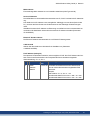
1.6 Mechanical Installation
For dimensions and cabinet mounting see (➜ # 60).
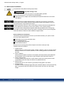
CAUTION
High EMC Voltage Level!
Risk of electrical shock, if drive (or motor) is not properly EMC-grounded.
Do not use painted (i.e. non-conductive) mounting plates.
Observe the hints in chapter "Recommendations for EMI noise reduction"in the Install-
ation Manual
Protect the drive from impermissible stresses. In particular, do not let any components
become bent or any insulation distances altered during transport and handling. Avoid con-
tact with electronic components and contacts.
The drive will switch itself off in case of overheating. Ensure that there is an adequate flow
of cool, filtered air into the bottom of the control cabinet, or use a heat exchanger.
Do not mount devices that produce magnetic fields directly beside the drive. Strong mag-
netic fields can directly affect internal components. Install devices which produce magnetic
field with distance to the drives and/or shield the magnetic fields.
Guide to Mechanical Installation
The following tools are required (at a minimum) to install the AKD2G; your specific install-
ation may require additional tools:
M5 hexagon socket-cap screws (ISO 4762)
4 mm T-handle Allen key
No. 2 Phillips head screwdriver
Small slotted screwdriver
Dimensions and mounting hole positions depend on the drive variant (➜ # 60).
Install the drive unit as follows:
1. Prepare the site.
Mount the drive in a closed control cabinet, ambient conditions (➜ # 16). The site must be
free from conductive or corrosive materials. For the mounting position in the cabinet see
(➜ # 60).
2. Check ventilation.
Check that the ventilation of the drive is unimpeded, and keep within the permitted ambi-
ent temperature (➜ # 16). Keep 50 mm space clearance above and below the drive.
3. Check cooling system.
If cooling systems are used for the control cabinet, position the cooling system so that
condensation water cannot drip onto the drive or peripheral devices.
4. Mount the drive.
Assemble the drive on the conductive, grounded mounting plate in the cabinet.
5. Ground the drive.
For EMC-compliant shielding and grounding see Installation Manual. Ground the mounting
plate, motor housing and CNC-GND of the control system and of the 24 V DC supply
voltage.
20 Kollmorgen | kdn.kollmorgen.com | Beta, December 2018
Seite laden ...
Seite laden ...
Seite laden ...
Seite laden ...
Seite laden ...
Seite laden ...
Seite laden ...
Seite laden ...
Seite laden ...
Seite laden ...
Seite laden ...
Seite laden ...
Seite laden ...
Seite laden ...
Seite laden ...
Seite laden ...
Seite laden ...
Seite laden ...
Seite laden ...
Seite laden ...
Seite laden ...
Seite laden ...
Seite laden ...
Seite laden ...
Seite laden ...
Seite laden ...
Seite laden ...
Seite laden ...
Seite laden ...
Seite laden ...
Seite laden ...
Seite laden ...
Seite laden ...
Seite laden ...
Seite laden ...
Seite laden ...
Seite laden ...
Seite laden ...
Seite laden ...
Seite laden ...
Seite laden ...
Seite laden ...
Seite laden ...
Seite laden ...
Seite laden ...
Seite laden ...
Seite laden ...
Seite laden ...
Seite laden ...
Seite laden ...
Seite laden ...
Seite laden ...
Seite laden ...
Seite laden ...
Seite laden ...
Seite laden ...
-
 1
1
-
 2
2
-
 3
3
-
 4
4
-
 5
5
-
 6
6
-
 7
7
-
 8
8
-
 9
9
-
 10
10
-
 11
11
-
 12
12
-
 13
13
-
 14
14
-
 15
15
-
 16
16
-
 17
17
-
 18
18
-
 19
19
-
 20
20
-
 21
21
-
 22
22
-
 23
23
-
 24
24
-
 25
25
-
 26
26
-
 27
27
-
 28
28
-
 29
29
-
 30
30
-
 31
31
-
 32
32
-
 33
33
-
 34
34
-
 35
35
-
 36
36
-
 37
37
-
 38
38
-
 39
39
-
 40
40
-
 41
41
-
 42
42
-
 43
43
-
 44
44
-
 45
45
-
 46
46
-
 47
47
-
 48
48
-
 49
49
-
 50
50
-
 51
51
-
 52
52
-
 53
53
-
 54
54
-
 55
55
-
 56
56
-
 57
57
-
 58
58
-
 59
59
-
 60
60
-
 61
61
-
 62
62
-
 63
63
-
 64
64
-
 65
65
-
 66
66
-
 67
67
-
 68
68
-
 69
69
-
 70
70
-
 71
71
-
 72
72
-
 73
73
-
 74
74
-
 75
75
-
 76
76


Kollmorgen AKD2G-S**-6V12 Product Safety Manual
- Typ
- Product Safety Manual
- Dieses Handbuch ist auch geeignet für
in anderen Sprachen
- English: Kollmorgen AKD2G-S**-6V12
Verwandte Papiere
-
Kollmorgen MKD-N240007 Product Safety Manual
-
Kollmorgen AKC-PCM-M Series Installationsanleitung
-
-
-
-
Kollmorgen AKM3 Benutzerhandbuch
-
-
-
-
Sonstige Unterlagen
-
Baumer Heat Sink Type D Datenblatt
-
Allied Brass 7220D-PNI Dimensions Guide
-
 Dryflow IFSM092A-ANON Series Benutzerhandbuch
-
Trendnet TV-SS1 Datenblatt
-
Ametek Dunkermotoren BG Series Assembly Instructions Manual
-
Schneider Electric XPSUDN Benutzerhandbuch
-
Honeywell N10XX Bedienungsanleitung
-
-
-
 Sprint Electric PL/X Schnellstartanleitung

