
Operating Instructions
Double channel Ex separator for
4 … 20 mA sensors
VEGATRENN 142
Document ID: 65695

2
Contents
VEGATRENN 142 •
65695-EN-210129
Contents
1 About this document ............................................................................................................... 4
1.1 Function ........................................................................................................................... 4
1.2 Target group ..................................................................................................................... 4
1.3 Symbols used................................................................................................................... 4
2 For your safety ......................................................................................................................... 5
2.1 Authorised personnel ....................................................................................................... 5
2.2 Appropriate use ................................................................................................................ 5
2.3 Warning about incorrect use ............................................................................................. 5
2.4 General safety instructions ............................................................................................... 5
2.5 Installation and operation in the USA and Canada ........................................................... 5
2.6 Safety instructions for Ex areas ........................................................................................ 6
3 Product description ................................................................................................................. 7
3.1 Conguration .................................................................................................................... 7
3.2 Principle of operation........................................................................................................ 7
3.3 Adjustment ....................................................................................................................... 7
3.4 Packaging, transport and storage ..................................................................................... 8
4 Mounting ................................................................................................................................... 9
4.1 General instructions ......................................................................................................... 9
5 Connecting to power supply ................................................................................................. 10
5.1 Preparing the connection ............................................................................................... 10
5.2 Anschlussschritte ........................................................................................................... 11
5.3 Anschlussplan ................................................................................................................ 12
6 Setup ....................................................................................................................................... 13
6.1 Bediensystem ................................................................................................................ 13
6.2 Adjustment elements ...................................................................................................... 13
7 Diagnostics and servicing .................................................................................................... 15
7.1 Maintenance .................................................................................................................. 15
7.2 Rectify faults ................................................................................................................... 15
7.3 How to proceed if a repair is necessary .......................................................................... 15
8 Dismount................................................................................................................................. 17
8.1 Dismounting steps.......................................................................................................... 17
8.2 Disposal ......................................................................................................................... 17
9 Certicatesandapprovals .................................................................................................... 18
9.1 Approvals for Ex areas ................................................................................................... 18
9.2 EU conformity ................................................................................................................. 18
9.3 SIL conformity (optional) ................................................................................................ 18
9.4 Environment management system ................................................................................. 18
10 Supplement ............................................................................................................................ 19
10.1 Technical data ................................................................................................................ 19
10.2 Maße .............................................................................................................................. 21
10.3 Industrial property rights ................................................................................................. 22
10.4 Trademark ...................................................................................................................... 22

3
Contents
VEGATRENN 142 •
65695-EN-210129
Editing status: 2021-01-27

4
1 About this document
VEGATRENN 142 •
65695-EN-210129
1 About this document
1.1 Function
This instruction provides all the information you need for mounting,
connection and setup as well as important instructions for mainte-
nance,faultrectication,theexchangeofpartsandthesafetyofthe
user. Please read this information before putting the instrument into
operation and keep this manual accessible in the immediate vicinity
of the device.
1.2 Target group
This operating instructions manual is directed to trained personnel.
Thecontentsofthismanualmustbemadeavailabletothequalied
personnel and implemented.
1.3 Symbols used
Document ID
This symbol on the front page of this instruction refers to the Docu-
ment ID. By entering the Document ID on www.vega.com you will
reach the document download.
Information, note, tip: This symbol indicates helpful additional infor-
mation and tips for successful work.
Note: This symbol indicates notes to prevent failures, malfunctions,
damage to devices or plants.
Caution: Non-observance of the information marked with this symbol
may result in personal injury.
Warning: Non-observance of the information marked with this symbol
may result in serious or fatal personal injury.
Danger: Non-observance of the information marked with this symbol
results in serious or fatal personal injury.
Ex applications
This symbol indicates special instructions for Ex applications.
•
List
The dot set in front indicates a list with no implied sequence.
1 Sequence of actions
Numbers set in front indicate successive steps in a procedure.
Battery disposal
This symbol indicates special information about the disposal of bat-
teries and accumulators.

5
2 For your safety
VEGATRENN 142 •
65695-EN-210129
2 For your safety
2.1 Authorised personnel
All operations described in this documentation must be carried out
onlybytrained,qualiedpersonnelauthorisedbytheplantoperator.
During work on and with the device, the required personal protective
equipment must always be worn.
2.2 Appropriate use
VEGATRENN 142 is an [Ex ia] separator with separate power supply
for connection of 4 … 20 mA/HART sensors in two-wire version.
Youcannddetailedinformationabouttheareaofapplicationin
chapter " Product description".
Operational reliability is ensured only if the instrument is properly
usedaccordingtothespecicationsintheoperatinginstructions
manual as well as possible supplementary instructions.
2.3 Warning about incorrect use
Inappropriate or incorrect use of this product can give rise to applica-
tion-specichazards,e.g.vesseloverllthroughincorrectmounting
or adjustment. Damage to property and persons or environmental
contamination can result. Also, the protective characteristics of the
instrument can be impaired.
2.4 General safety instructions
This is a state-of-the-art instrument complying with all prevailing
regulations and directives. The instrument must only be operated in a
technicallyawlessandreliablecondition.Theoperatorisresponsi-
ble for the trouble-free operation of the instrument. When measuring
aggressive or corrosive media that can cause a dangerous situation
if the instrument malfunctions, the operator has to implement suitable
measures to make sure the instrument is functioning properly.
The safety instructions in this operating instructions manual, the na-
tional installation standards as well as the valid safety regulations and
accident prevention rules must be observed by the user.
For safety and warranty reasons, any invasive work on the device
beyond that described in the operating instructions manual may be
carried out only by personnel authorised by the manufacturer. Arbi-
traryconversionsormodicationsareexplicitlyforbidden.Forsafety
reasons,onlytheaccessoryspeciedbythemanufacturermustbe
used.
To avoid any danger, the safety approval markings and safety tips on
the device must also be observed.
2.5 Installation and operation in the USA and
Canada
This information is only valid for USA and Canada. Hence the follow-
ing text is only available in the English language.

6
2 For your safety
VEGATRENN 142 •
65695-EN-210129
Installations in the US shall comply with the relevant requirements of
the National Electrical Code (ANSI/NFPA 70).
Installations in Canada shall comply with the relevant requirements of
the Canadian Electrical Code.
2.6 Safety instructions for Ex areas
For Ex applications, only devices with corresponding Ex approval may
beused.ObservetheEx-specicsafetyinstructions.Thesearean
integral part of the operating instructions and are enclosed with every
device with Ex approval.

7
3 Product description
VEGATRENN 142 •
65695-EN-210129
3 Product description
3.1 Conguration
The scope of delivery encompasses:
•
VEGATRENN 142
•
Documentation
– This operating instructions manual
– Ex-specic"Safety instructions" (depending on the version)
– Ifnecessary,furthercerticates
Thetypelabelcontainsthemostimportantdataforidenticationand
use of the instrument:
•
Instrument type
•
Information about approvals
•
Technical data
•
Serial number of the instrument
•
QR code for device documentation
•
Number code for Bluetooth access
•
Manufacturer information
Move to " www.vega.com"andenterinthesearcheldtheserial
number of your instrument.
Thereyoucanndthefollowinginformationabouttheinstrument:
•
Order data
•
Documentation
•
Software
Alternatively,youcanndallviayoursmartphone:
•
Scan the QR-code on the type label of the device or
•
Enter serial number manually in the VEGA Tools app (available
free of charge in the respective stores)
3.2 Principle of operation
DasVEGATRENN142isteinzweikanaliger[EExia]-Speisetrenner
mitseparaterSpannungsversorgungzumAnschlussvonzwei
4…20mA/HART-SensoreninZweileiterausführung.Alszugehöriges
elektrisches Betriebsmittel stellt es eine galvanische Trennung
zwischenSensorstromkreisundAuswertstromkreisunddadurch
zwischenEx-undNicht-Ex-Bereichsicher.
An integrated transmitter power supply powers the connected sensor.
The current signal from the sensor (4 … 20 mA) is transferred to the
output linearly and galvanically separated. The instrument is HART
transparent, i.e. the HART signals are transmitted bidirectionally
between input and output.
3.3 Adjustment
NoadjustmentorcongurationofVEGATRENN142isnecessary.A
parameter adjustment of the connected sensors can be carried out
Scope of delivery
Type label
Documents and software
Anwendungsbereich
Functional principle

8
3 Product description
VEGATRENN 142 •
65695-EN-210129
via the HART communication sockets behind the hinged front cover.
Adjustment of the connected sensors is carried out preferably via a
Windows PC with a parameter adjustment software such as PACT-
ware and corresponding DTM. A VEGACONNECT interface adapter
or a HART modem is necessary for connecting the PC.
3.4 Packaging, transport and storage
Your instrument was protected by packaging during transport. Its
capacity to handle normal loads during transport is assured by a test
based on ISO 4180.
The packaging of standard instruments consists of environment-
friendly, recyclable cardboard. For special versions, PE foam or PE
foil is also used. Dispose of the packaging material via specialised
recycling companies.
Transport must be carried out in due consideration of the notes on the
transport packaging. Nonobservance of these instructions can cause
damage to the device.
The delivery must be checked for completeness and possible transit
damage immediately at receipt. Ascertained transit damage or con-
cealed defects must be appropriately dealt with.
Up to the time of installation, the packages must be left closed and
stored according to the orientation and storage markings on the
outside.
Unless otherwise indicated, the packages must be stored only under
the following conditions:
•
Not in the open
•
Dry and dust free
•
Not exposed to corrosive media
•
Protected against solar radiation
•
Avoiding mechanical shock and vibration
•
Storage and transport temperature see chapter " Supplement -
Technical data - Ambient conditions"
•
Relative humidity 20 … 85 %
Packaging
Transport
Transport inspection
Storage
Storage and transport
temperature

9
4 Mounting
VEGATRENN 142 •
65695-EN-210129
4 Mounting
4.1 General instructions
VEGATRENN 142 is designed for carrier rail mounting (top hat rail
35 x 7.5 according to DIN EN 50022/60715). Due to its protection
rating of IP20, the instrument is suitable for mounting in switching
cabinets.Itcanbemountedhorizontallyandvertically.
Note:
When several instruments are mounted together without space in
between, the ambient temperature at the installation location of the
instrument must not exceed 60 °C. Around the ventilation slots there
must be a distance of at least 2 cm to the next component.
VEGATRENN 142 is a corresponding, intrinsically safe equipment
andmustnotbeinstalledinhazardousareasofzone0/1.Asafe
operation is only ensured if the operating instructions and EU type
approvalcerticateareobserved.VEGATRENN142mustnotbe
opened.
A distance of 50 mm to the intrinsically safe terminals must be en-
sured when mounting.
The instrument is suitable for standard and extended ambient condi-
tions acc. to DIN/EN/IEC/ANSI/ISA/UL/CSA 61010-1.
Makesurethattheenvironmentalandambientconditionsspeciedin
chapter " Technical data" are maintained.
Mounting options
Ambient conditions

10
5 Connecting to power supply
VEGATRENN 142 •
65695-EN-210129
5 Connecting to power supply
5.1 Preparing the connection
Always keep in mind the following safety instructions:
Warning:
Connect only in the complete absence of line voltage.
•
Connect only in the complete absence of line voltage
•
If overvoltage surges are expected, overvoltage arresters should
be installed
Note:
Install a disconnecting device for the instrument which is easy to
access. The disconnecting device must be marked for the instrument
(IEC/EN 61010).
Inhazardousareasyoumusttakenoteoftherespectiveregulations,
conformityandtypeapprovalcerticatesofthesensorsandpower
supply units.
Thedataforpowersupplyarespeciedinchapter"Technical data".
The voltage supply of VEGATRENN 142 is connected with standard
cable according to the national installation standards.
Make sure that the cable used has the required temperature resist-
anceandresafetyformax.occurringambienttemperature
The sensors are connected with standard two-wire cable without
shielding. If electromagnetic interference is expected which is above
the test values of EN 61326 for industrial areas, shielded cable should
be used. In general, cable screening is necessary in HART multidrop
mode.
Connect the cable shielding on both ends to ground potential. In
the sensor, the shielding must be connected directly to the internal
ground terminal. The ground terminal on the outside of the sensor
housing must be connected to the potential equalisation (low imped-
ance).
If potential equalisation currents are expected, the connection on the
processing side must be made via a ceramic capacitor (e. g. 1 nF,
1500 V). The low-frequency potential equalisation currents are thus
suppressed,buttheprotectiveeectagainsthighfrequencyinterfer-
ence signals remains.
Take note of the corresponding installation regulations for Ex applica-
tions. In particular, make sure that no potential equalisation currents
owoverthecablescreen.Incaseofgroundingonbothsidesthis
can be achieved by the use of a capacitor or a separate potential
equalisation.
The instrument is equipped with communication sockets in the front
for connection of a VEGACONNECT or another HART handheld as
well as an integrated HART resistor.
Safety instructions
Safety instructions
for Ex applications
Voltage supply
Connection cable
Cable screening and
grounding
Connection cable
for Ex applications
HART communication

11
5 Connecting to power supply
VEGATRENN 142 •
65695-EN-210129
If the resistance of the connected processing system is less than
230Ω,thedigitaladjustmentsignalisextremelydampedorshort-cir-
cuited. Digital communication with the PC is then no longer possible.
Withlowimpedanceprocessingsystems,aresistorofapprox.230Ω
must be looped into the 4 … 20 mA cable. This resistor is already inte-
grated in VEGATRENN 142 and can be chosen through the selection
of the respective terminals.
No additional resistor is required in the sensor circuit for direct con-
nection of a HART-Master. When connecting a VEGADIS 82, the com-
munication resistor in the VEGADIS 82 must be deactivated.
In HART multidrop mode, the measured values are transmitted
on the same cable (bus) as the digital HART signals. An analogue
4 … 20 mA transmission is not possible, the current is limited to 4 mA.
An own, unambiguous address (address range 1-15) must be as-
signedtoeachconnectedsensor.Inthismode,uptovesensorscan
be connected to one channel.
Information:
When using a HART resistor, keep in mind that there is an additional
voltageloss.Youcannddetailsinchapter"Technical data".
5.2 Anschlussschritte
DiesteckbarenAnschlussklemmenkönnenbeiBedarfzumbeque-
menAnschlussabgezogenwerden.ZumelektrischenAnschluss
gehen Sie wie folgt vor:
1. Gerät wie im vorherigen Kapitel beschrieben montieren
2. Sensorleitung2anKlemme4/5anschließen,ggf.Schirmaue-
gen
3. Sensorleitung1anKlemme1/2anschließen,ggf.Schirmaue-
gen
4. Stromlos geschaltete Spannungsversorgung an Klemme 16/17
anschließen
5. Auswertstromkreis2,z.B.vonSPSanKlemme14/15oder13/15
(mitHART-Widerstand)anschließen,ggf.Schirmauegen
6. Auswertstromkreis1,z.B.vonSPSanKlemme11/12oder10/12
(mitHART-Widerstand)anschließen,ggf.Schirmauegen
Der elektrische Anschluss ist somit fertig gestellt.
Note:
Sollen mehrere Sensoren im HART-Multidropbetrieb angeschlos-
sen werden, muss jedem Sensor vor dem Anschluss an das
VEGATRENN142eineentsprechendeHART-Adressezugewiesen
werden.
HART multidrop mode

12
5 Connecting to power supply
VEGATRENN 142 •
65695-EN-210129
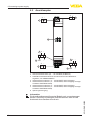
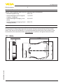
5.3 Anschlussplan
1
7
6
3
5
4
8
2
13 14 15
-+
-+
-
+H
1 2
-+
16 17
-+
4 5
10 11 12
-
+
-
+H
1 Sensorstromkreis Kanal 1 (4 … 20 mA/HART, Ex-Bereich)
2 Sensorstromkreis Kanal 2 (4 … 20 mA/HART, Ex-Bereich)
3 HART-Kommunikationsbuchsen zum Anschluss eines HART-Bedi-
engerätes, z. B. VEGACONNECT
4 Auswertstromkreis Kanal 1 (4 … 20 mA/HART, aktiver Ausgang)
5 Auswertstromkreis Kanal 1 (4 … 20 mA/HART, aktiver Ausgang mit einge-
schleiftem HART-Widerstand)
6 Auswertstromkreis Kanal 2 (4 … 20 mA/HART, aktiver Ausgang)
7 Auswertstromkreis Kanal 2 (4 … 20 mA/HART, aktiver Ausgang mit einge-
schleiftem HART-Widerstand)
8 Spannungsversorgung
Information:
DieAnschlussklemmenkönnenbeiBedarfnachvorneabgezogen
werden.DieskannbeibeengtenPlatzverhältnissenoderfürden
Austausch eines Gerätes sinnvoll sein.

13
6 Setup
VEGATRENN 142 •
65695-EN-210129
6 Setup
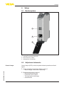
6.1 Bediensystem
1
2
3
Fig. 1: Anzeige- und Bedienelemente
1 HART-Kommunikationsbuchsen
2 Kontrollleuchten (LEDs)
3 Aufklappbare Frontblende
6.2 Adjustment elements
Control lamps (LED) in the front plate indicate operation and fault
signal.
•
Green operating control lamp lights in case of
– Mains voltage, instrument is operating
•
Red fault lamp lights in case of
– Short-circuit on the input
– Line break on the output
– Too high load on the output
– Internal faults
Control lamps

14
6 Setup
VEGATRENN 142 •
65695-EN-210129
The adjustment elements are located under a hinged front cover. To
open it, use a small screwdriver in conjunction with the slot on the
upper side of the front cover. To close it, push the cover at bottom and
toprmlyontothefrontcoveruntilyouhearthetworetainingclips
snap in.
AmVEGATRENN142selbstistkeineBedienungoderKonguration
erforderlich. Über die HART-Kommunikationsbuchsen kann eine Par-
ametrierung der angeschlossenen HART-Sensoren ohne Unterbrech-
nung des Messkreises vorgenommen werden. Der für diesen Zweck
benötigteWiderstand(230Ω)istbeimAnschlussderKlemmen10/12
(Kanal1)bzw.13/15(Kanal2)bereitsimVEGATRENN142integriert.
Die Bedienung des angeschlossenen Sensors erfolgt über einen
Windows-PCmiteinerParametrierungssoftware,wiez.B.PACTware
und entsprechendem DTM.
Front cover
HART-Kommunikations-
buchsen

15
7 Diagnostics and servicing
VEGATRENN 142 •
65695-EN-210129
7 Diagnostics and servicing
7.1 Maintenance
If the device is used properly, no special maintenance is required in
normal operation.
The cleaning helps that the type label and markings on the instrument
are visible.
Take note of the following:
•
Use only cleaning agents which do not corrode the housings, type
label and seals
•
Use only cleaning methods corresponding to the housing protec-
tion rating
7.2 Rectify faults
The operator of the system is responsible for taking suitable meas-
ures to rectify faults.
Maximum reliability is ensured. Nevertheless, faults can occur during
operation. These may be caused by the following, e.g.:
•
Voltage supply
•
Interference in the cables
Therstmeasuretobetakenistochecktheinput/outputsignalas
well as the power supply. In many cases, the causes can be deter-
minedandfaultscanbequicklyrectied.
Depending on the reason for the fault and the measures taken, the
steps described in chapter " Setup" must be carried out again or must
be checked for plausibility and completeness.
Should these measures not be successful, please call in urgent cases
the VEGA service hotline under the phone no. +49 1805 858550.
The hotline is also available outside normal working hours, seven
days a week around the clock.
Sinceweoerthisserviceworldwide,thesupportisprovidedin
English. The service itself is free of charge, the only costs involved are
the normal call charges.
7.3 How to proceed if a repair is necessary
Youcanndaninstrumentreturnformaswellasdetailedinforma-
tion about the procedure in the download area of our homepage:
www.vega.com.
By doing this you help us carry out the repair quickly and without hav-
ing to call back for needed information.
If a repair is necessary, please proceed as follows:
•
Printandlloutoneformperinstrument
•
Clean the instrument and pack it damage-proof
Maintenance
Cleaning
Reaction when malfunc-
tion occurs
Causes of malfunction
Faultrectication
Reaction after fault recti-
cation
24 hour service hotline


17
8 Dismount
VEGATRENN 142 •
65695-EN-210129
8 Dismount
8.1 Dismounting steps
Take note of chapters " Mounting" and " Connecting to voltage sup-
ply" and carry out the listed steps in reverse order.
8.2 Disposal
The device is made of recyclable materials. For this reason, it should
be disposed of by a specialist recycling company. Observe the ap-
plicable national regulations.

18
9Certicatesandapprovals
VEGATRENN 142 •
65695-EN-210129
9 Certicatesandapprovals
9.1 Approvals for Ex areas
Approvedversionsforuseinhazardousareasareavailableorin
preparation for the device series.
Youcanndtherelevantdocumentsonourhomepage.
9.2 EU conformity
ThedevicefullsthelegalrequirementsoftheapplicableEUdirec-
tives.ByaxingtheCEmarking,weconrmtheconformityofthe
instrument with these directives.
The EU conformity declaration can be found on our homepage.
9.3 SIL conformity (optional)
InstrumentswithSILoptionfullltherequirementsoffunctionalsafety
accordingtoIEC61508.Youcanndfurtherinformationinthesup-
plied Safety Manual.
9.4 Environment management system
Protection of the environment is one of our most important duties.
That is why we have introduced an environment management system
with the goal of continuously improving company environmental pro-
tection.Theenvironmentmanagementsystemiscertiedaccording
toDINENISO14001.Pleasehelpusfullthisobligationbyobserv-
ing the environmental instructions in chapters " Packaging, transport
and Lagestoragerung", " Disposal" of these operating instructions.

19
10 Supplement
VEGATRENN 142 •
65695-EN-210129
10 Supplement
10.1 Technical data
Note for approved instruments
The technical data in the respective safety instructions are valid for approved instruments (e.g. with
Exapproval).Insomecases,thesedatacandierfromthedatalistedherein.
All approval documents can be downloaded from our homepage.
General data
Series Module unit for mounting on carrier rails 35 x 7.5 acc. to
EN 50022/60715
Weight 160g(5.14oz)
Housing material Polycarbonate PC-FR
Connection terminals
Ʋ Type of terminal Screw terminal
Ʋ Wire cross-section 0.25 mm² (AWG 23) … 2.5 mm² (AWG 12)
HART communication sockets ø 2 mm
Spannungsversorgung
Betriebsspannung
Ʋ Nennspannung DC 24 … 31 V (-15 %, +10 %)
Max. Leistungsaufnahme 3 W
Sensorstromkreis
AnzahlSensoren 2 x 4 … 20 mA/HART (5 x HART-Multidrop pro Kanal)
Eingangsart Aktiv (Sensorversorgung durch VEGATRENN 142)
Klemmenspannung 21 … 16,5 V DC bei 4 … 20 mA
Leerlaufspannung 24 V DC (+/- 1 V)
Kurzschlussstrom < 26 mA
Restwelligkeit < 50 mV RMS
Auswertstromkreis
Anzahl 2 x 4 … 20 mA/HART
Ausgangsart Aktiv
Leerlaufspannung < 15,5 V DC
Restwelligkeit des Ausgangsstromes < 50 µA RMS
StrombeiKurzschlussamEingang < 10 µA
Strom ohne angeschlossenen Sensor
Ʋ Im Bereich +20 … +60 °C
(+68 … +140 °F)
< 50 µA
Ʋ Im Bereich -20 … +20 °C
(-4 … +68 °F)
< 200 µA

20
10 Supplement
VEGATRENN 142 •
65695-EN-210129
Max. anschließbare Bürde
1)
Ʋ bei 20 mA 600 Ohm
Ʋ bei 22 mA 550 Ohm
Deviation
Reference conditions Calibration temperature 25 °C (77 °F)
Linearity < 0.1 %
Inuenceoftheambienttemperature
Ʋ In the range of +20 … +60 °C
(+68 … +140 °F)
< 0.2 %
Ʋ In the range of -20 … +20 °C
(-4 … +68 °F)
< 0.6 %
Deviation due to strong, high-frequency
electromagneticelds(EN61326)
< 0.5 %
Integrated HART resistor
Resistance value 232Ω
Indicators
LED displays
Ʋ Status, operating voltage LED green
Ʋ Status, fault signal LED red
Ambient conditions
Ambient temperature at the installation
site of the instrument
-20 … +60 °C (-4 … +140 °F)
Storage and transport temperature -40 … +70 °C (-40 … +158 °F)
Relative humidity < 96 %
Mechanical environmental conditions
Vibrations (oscillations) Class4M4acc.toIEC60721-3-4(1g,4…200Hz)
Impacts (mechanical shock) Class 6M4 acc. to IEC 60721-3-6 (10 g/11 ms,
30 g/6 ms, 50 g/2.3 ms)
Electrical protective measures
Protection rating IP20
Overvoltage category (IEC 61010-1)
Ʋ up to 2000 m (6562 ft) above sea level II
Ʋ up to 5000 m (16404 ft) above sea
level
II - Only with connected overvoltage protection with
response voltage of < 1000 V
Ʋ up to 5000 m (16404 ft) above sea
level
I
Protection class II
1)
OhneinternenHART-Widerstand(beiAnschlussanKlemme11/12bzw.Klemme14/15)
Seite wird geladen ...
Seite wird geladen ...
Seite wird geladen ...
Seite wird geladen ...
-
 1
1
-
 2
2
-
 3
3
-
 4
4
-
 5
5
-
 6
6
-
 7
7
-
 8
8
-
 9
9
-
 10
10
-
 11
11
-
 12
12
-
 13
13
-
 14
14
-
 15
15
-
 16
16
-
 17
17
-
 18
18
-
 19
19
-
 20
20
-
 21
21
-
 22
22
-
 23
23
-
 24
24


in anderen Sprachen
Verwandte Artikel
-
Vega VEGATRENN 142 Bedienungsanleitung
-
Vega VEGATRENN 152 Bedienungsanleitung
-
Vega VEGATRENN 151 Bedienungsanleitung
-
Vega VEGATRENN 141 Bedienungsanleitung
-
-
-
-
 Vega VEGATRENN 149A Ex Bedienungsanleitung
-
 Vega VEGATRENN 149A Ex Bedienungsanleitung
-

