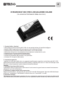
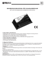
Teleco TSP 100W regolatore uno Benutzerhandbuch
- Typ
- Benutzerhandbuch

1. Caratteristiche e funzioni:
• Utilizzo dello standard industriale MCU SCM e di uno speciale software di controllo intelligente.
• Modalità PWM di regolazione della carica per una carica ad elevata efficienza.
• Protezione contro l’inversione di polarità della batteria, sovra e sotto tensione.
• Riattivazione del carico in uscita, protezioni da sovracorrente e cortocircuito in uscita.
• Protezione contro il cortocircuito del pannello solare
• Protezione contro l’apertura del circuito della batteria
• Funzione di rilevamento della tensione ad alta precisione
• Indicatore LED di capacità della batteria
2. Introduzione generale
I regolatori di carica solare della serie sc-xa, progettati specificamente secondo lo standard industriale MCU SCM,
garantiscono prestazioni ottimali ed una qualità eccellente. I regolatori della serie sc-xa sono stati ideati per essere
utilizzati in sistemi fotovoltaici installati a bordo di Veicoli Ricreazionali.
Funzioni:
1) Funzione di gestione della batteria:
La protezione contro la sovraccarica e quella contro la scarica eccessiva garantiscono un corretto funzionamento
allungando la vita utile della batteria.
2) Funzione di compensazione della temperatura:
Regola automaticamente i dati impostati per i parametri di controllo del programma di gestione della batteria per
evitare una "sottotensione" della batteria in inverno ed una sua “sovraccarica” in estate.
3) Protezioni multiple:
Collegamento inverso della batteria, protezioni da sovra e sottotensione, protezione contro il cortocircuito del pannello
solare. Riattivazione automatica della tensione in uscita e protezioni contro il cortocircuito della tensione in uscita.
IT
ISTRUZIONI D’USO PER IL REGOLATORE SOLARE
(DA LEGGERE ATTENTAMENTE PRIMA DELL’USO!)

INVERTER
BATTERIA
CARICO
SENSORE DI TEMPERATURA
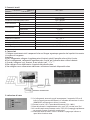
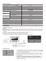
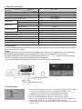
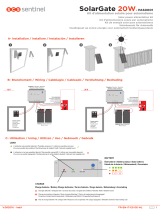
4. Connessioni
1) Collegare correttamente tutti i componenti in base al disegno seguente per garantire che la polarità sia corretta.
La sequenza è la seguente:
Attenzione:
a) Per il collegamento, collegare al regolatore prima la batteria, quindi il pannello solare e infine il carico.
b) Per lo scollegamento, scollegare dal regolatore prima il carico, poi il pannello solare e infine le batterie
c) Quando si collegano i cavi, accertarsi di non invertire i poli "+" e "-".
d) Non collegare il cavo della batteria al terminale del pannello solare.
e) Non collegare nessun alimentatore stabilizzato o caricatore al terminale del pannello solare.
5. Indicazione di stato
5.1 Se i collegamenti sono stati eseguiti correttamente, il numero dei LED verdi
indica la capacità corretta della batteria e l’indicatore della tensione in uscita
(POWER OUT nell’immagine a sinistra) si accende.
5.2 Durante la carica i LED si accendono ciclicamente (25%~100%).
5.3 Quando la batteria è completamente carica, tutti i LED restano accesi fissi.
5.4 In caso di batteria eccessivamente scarica, il LED (25%) lampeggia rapidamente
per avvertire l’utente di sostituirla quanto prima.
5.5 L’indicatore della tensione in uscita si accende o si spegne per indicare se
quest’ultima è attiva o meno.
3. Parametri tecnici
Tensione nominale
Corrente nominale
Protezione da sovraccarica
Tensione di riattivazione della carica
Modello n°
Parametri
Scarica eccessiva
Sovratensione
Caduta di tensione
Disattivazione
Riattivazione
Disattivazione
Riattivazione
Tra ingresso e batterie
Tra batterie e carico
Assorbimento di corrente senza carico
Temperatura ambiente
Altitudine
Dimensioni (LxPxH in mm)
Peso (kg)
Fattore di compensazione termica
SPC 10/1
12V
10A
14,4 ± 0,3 Vdc
13,3 ± 0,3 Vdc
11 ± 0,3Vdc
12 ± 0,3 Vdc
17 Vdc
15,0 Vdc
0,5 Vdc
0,2 Vdc
< 5mA
-10
~ +55 °C
5500m
164x100x48
0,39
28
~ 32 mV/cell. in °C

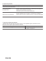
7. Guida alla risoluzione dei problemi
I regolatori della serie HSR12VXX sono di buona qualità. In caso di problemi o guasti, controllare le unità in
base alle istruzioni seguenti oppure contattare il fornitore.
Problema
L’indicatore di carica lampeggia
Soluzione
Le batterie sono state collegate in modo errato;
correggere il collegamento
6. Funzione di protezione
Tipo di protezione
Inversione delle polarità della batteria
Inversione delle polarità
del modulo solare
Apertura del circuito delle batterie
Dettagli
Un segnale acustico indica che le polarità sono state invertite.
Quando si collega il pannello fotovoltaico, se la polarità non viene rispettata, il
regolatore entra in protezione e non funziona
A correzione avvenuta l’unità funzionerà regolarmente.
Quando il regolatore solare è in funzione, ma la batteria non è collegata, il
regolatore limita la tensione in modo da evitare che il carico venga danneggiato.

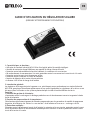
1. Caractéristiques et fonctions :
• Utilisation du standard industriel MCU SCM et d’un logiciel spécial de contrôle intelligent.
• Contrôle de tension de charge PWM pour une capacité de charge à haute efficacité.
• Protection contre le branchement inversé de la batterie, la surtension et la sous-tension.
• Ré-enclenchement du consommateur à la sortie, protection contre le sur-courant ou le court-circuit à la sortie.
• Protection contre le court-circuit du panneau solaire
• Protection contre l’ouverture du circuit de la batterie
• Fonction de détection de la tension à haute précision
• Indicateur à LED d’état de charge de la batterie
2. Introduction générale
Les régulateurs de charge solaire de la gamme sc-xa, spécialement conçus conformément au standard industriel
MCU SCM, garantissent d’excellentes performances et une qualité impeccable. Les régulateurs de la série sc-xa ont
été conçus pour l’utilisation sur des systèmes photovoltaïques installés à bord de Véhicules de Loisirs.
Fonctions :
1) Fonction de gestion de la batterie :
La protection contre la surcharge et la décharge profonde assure le fonctionnement correct et augmente la durée
de vie de la batterie.
2) Fonction de compensation de la température :
Cette fonction règle automatiquement les données programmées pour les paramètres de contrôle du programme
de gestion de la batterie, afin d’éviter la « sous-tension » de la batterie en hiver ou sa « surcharge » en été.
3) Protections multiples :
Protection contre le branchement inversé de la batterie, la surtension et la sous-tension, protection contre le court-
circuit du panneau solaire. Ré-enclenchement automatique de la tension à la sortie et protections contre le court-
circuit de la tension à la sortie.
FR
GUIDE D’UTILISATION DU RÉGULATEUR SOLAIRE
(LIRE AVEC ATTENTION AVANT L’UTILISATION!)

CONSOMMATEUR
BATTERIE
CHARGE
CAPTEUR DE TEMPÉRATURE
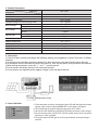
4. Raccordement
1) Raccordez correctement tous les composants, conformément au plan suivant, pour garantir la polarité correcte. Opérez
en respectant l’ordre suivant :
Attention
a) Pour le raccordement, raccordez au régulateur d’abord la batterie, puis le panneau solaire et pour finir, le consommateur.
b) Pour le débranchement, débranchez du régulateur d’abord le consommateur, puis le panneau solaire et, pour finir, les
batteries.
c) Quand vous raccordez les câbles, assurez-vous de ne pas inverser les pôles “+” et “-”.
d) Ne branchez pas le câble de la batterie sur la borne du panneau solaire.
e) Ne branchez aucun alimentateur stabilisé ou chargeur sur la borne du panneau solaire.
5. Indication d’état
5.1 Si le raccordement a été correctement réalisé, le nombre des LED verts indique
la capacité correcte de la batterie et l’indicateur de la tension à la sortie (POWER
OUT dans l’image à gauche) s’allume.
5.2 Au cours de la charge, les LED s’allument de manière cyclique (25%~100%).
5.3 Quand la batterie est complètement chargée, toutes les LED restent allumées
en permanence.
5.4 En cas de décharge profonde de la batterie, la LED (25%) clignote rapidement
pour signaler à l’utilisateur qu’il doit remplacer au plus tôt la batterie.
5.5 L’indicateur de tension à la sortie s’allume ou s’éteint pour indiquer si cette
dernière est active ou pas.
3. Parametri tecnici
Tension nominale
Courant nominal
Protection contre la surcharge
Tension de ré-enclenchement de la charge
Modèle n°
Caractéristiques
Décharge profonde
Surtension
Chute de tension
Désactivation
Ré-enclenchement
Désactivation
Ré-enclenchement
E
ntre entrée et batteries
Entre batteries et consommateur
Absorption de courant sans consommateur
Température ambiante
Altitude
Dimensions (LxPxH en mm)
Poids (kg)
Compensation de température
SPC 10/1
12V
10A
14,4 ± 0,3 Vdc
13,3 ± 0,3 Vdc
11 ± 0,3Vdc
12 ± 0,3 Vdc
17 Vdc
15,0 Vdc
0,5 Vdc
0,2 Vdc
< 5mA
-10
~ +55 °C
5500m
164x100x48
0,39
28
~ 32 mV/cell. in °C

7. Guide à la résolution des problèmes
Les régulateurs de la série HSR12VXX sont de bonne qualité. En cas de problèmes ou de dysfonctionnements,
contrôlez les unités conformément aux instructions suivantes ou bien contactez le fournisseur.
Problème
Le témoin d’état de charge clignote
Solution
Les batteries ont été mal raccordées ; corriger le
raccordement
6. Fonction de protection
Type de protection
Inversion des polarités de la batterie
Inversion des polarités du module solaire
Ouverture du circuit des batteries
Détails
Un signal sonore indique que les polarités ont été inversées.
Au branchement du panneau photovoltaïque, si la polarité n’est pas respectée, la
protection du régulateur se déclenche et le régulateur ne marche pas.
L’appareil recommence à fonctionner régulièrement une fois que l’erreur a été
corrigée.
Quand le régulateur solaire est en marche, mais que la batterie n’est pas branchée,
le régulateur limite la tension pour ne pas abîmer le consommateur.

1. Features and Functions:
• Adopts industrial degree MCU SCM and special software, for an intelligent control.
• PWM charging control mode, charge in high efficient.
• Protection against: battery reverse connection, over-voltage and low-voltage.
• Load output resume, output over-current, and output short-circuit protections.
• Solar panel short-circuit protection
• Battery open circuit protection
• High precision voltage recognition function
• LED indication for battery capacity
2. General Introduction
The sc-xA series solar charge controllers are specifically designed according to the industrial degree MCU SCM
ensuring great performance and excellent quality. The sc-xA series controllers are designed for solar power systems
to be installed on Recreational Vehicles.
Functions:
1) Battery management function:
Over-charge protection and over-discharge protection ensure normal use and prolong the life of the battery.
2) Temperature compensation function:
Auto adjust the data settings of the battery management program to control parameters to avoid battery "under-
voltage" in winter and "over-charge" in summer.
3) Multi-protections:
Battery reverse connection, over-voltage and low-voltage protections, solar panel short-circuit protection. Auto-
resuming of the output voltage, and protections against output voltage short-circuit.
GB
USER MANUAL FOR SOLAR CONTROLLER
(PLEASE READ CAREFULLY BEFORE USING!)

INVERTER
BATTERY
LOAD
TEMPERTATURE SENSOR
4. Connections
1) Connect all parts correctly according to the following drawing, ensuring polarity is correct. The order is as follows:
Attention:
a) To connect to the controller: connect the battery first, then connect the solar panel, finally connect the load.
b) To disconnect from the controller: disconnect the load first, then the solar panel, finally disconnect the batteries.
c) When making connections, ensure the "+" and "-" are not reversed.
d) Do not connect the battery directly to the solar panel terminal.
e) Do not connect any regulated power supply or charger to the solar panel terminal.
5. Status Indication
5.1 If the connections are correct, the number of green LEDs will show the correct battery
capacity and the output indicator (POWER OUT-see left image ) will light on.
5.2 The LED will light up cyclically during charging status (25%-100%).
5.3 All the LEDs will stop blinking and light on fixed when the battery is fully charged.
5.4 In over-discharge status, the LED (25%) will flash quickly to warn the user to replace
the battery as soon as possible.
5.5 The power output LED will light on or off to signal whether the output voltage is
activated.
3. Technical Parameters
Rated Voltage
Rated Current
Over-Charge Protection
Threshold voltage to restart charging mode
Model No.
Parameters
Over-Discharge
Over-Voltage
Voltage Drop
Cut-off
Resume
Cut-off
Resume
Between input and batteries
Between batteries and load
No Load Current Draw
Ambient Temperature
Altitude
Size (LxWxH: mm)
Weight (Kg)
i Temp. Compensated factor
SPC 10/1
12V
10A
14,4 ± 0,3 Vdc
13,3 ± 0,3 Vdc
11 ± 0,3Vdc
12 ± 0,3 Vdc
17 Vdc
15,0 Vdc
0,5 Vdc
0,2 Vdc
< 5mA
-10
~ +55 °C
5500m
164x100x48
0,39
28
~ 32 mV/cell. in °C

7. Trouble Shooting Guide
The HSR12VXX series controllers are of good quality; if you have any trouble or problem, please check the
units as follows or contact the supplier:
Problem
The charge indicator is flashing
Solution
The battery has been wrongly connected;
restore the right connection.
6. Protection Function
Protection item
Battery reversal polarity
Solar module reversal polarity
Battery open-circuit Protection
Details
The buzzer will warn when reverse connected.
When you connect the solar panel, if the polarity is not properly respected, its
protection system will be activated, not allowing the charge controller to work.
Once the polarity connections are properly restored, the unit will start working
properly again.
When the solar controller is on, but the battery is not connected, the solar controller
will limit the voltage to prevent the load from getting damaged.

1. Eigenschaften und Funktionen:
• Anwendung des MCU SCM-Industriestandards und einer speziellen intelligenten Steuerungssoftware.
• PWM-Modus für die Laderegelung für ein hocheffizientes Aufladen.
• Verpolungsschutz der Batterie sowie vor Über- und Unterspannung.
• Wiederaktivierung der Ausgangsladung, Schutz vor Überstrom und Ausgangskurzschluss.
• Schutz vor Kurzschluss am Solarpanel
• Schutz vor Batteriekreisunterbrechung
• hochpräzise Spannungsmessfunktion
• LED-Anzeige für die Batteriekapazität
2. Allgemeine Einführung
Die spezifisch nach dem MCU SCM-Industriestandard konzipierten Solarladeregler der Serie sc-xa garantieren optimale
Leistungen und eine ausgezeichnete Qualität. Die Laderegler der Serie sc-xa wurden für die Anwendung von in
Freizeitfahrzeugen installierten Fotovoltaiksystemen entworfen.
Funktionen:
1) Steuerfunktion der Batterie:
Der Überlastschutz und der Tiefentladeschutz garantieren einen korrekten Betrieb und verlängern die Nutzdauer der
Batterie.
2) Temperaturausgleichfunktion:
Regelt automatisch die für die Steuerparameter des Batterie-Verwaltungsprogramms eingestellten Daten, um eine
„Unterspannung“ der Batterie während der Winterzeit bzw. eine „Überlast“ derselben während der Sommerzeit
zu unterbinden.
3) Mehrfachschutz:
Batterieverpolung, Schutz vor Über- und Unterspannung, Schutz vor Kurzschluss am Solarpanel. Automatische
Wiederaktivierung der Ausgangsspannung und Schutz vor Kurzschluss der Ausgangsspannung.
D
BEDIENUNGSANLEITUNG FÜR SOLARLADEREGLER
(BITTE VOR DER ANWENDUNG AUFMERKSAM DURCHLESEN!)

WECHSELRICHTER
BATTERIE
LAST
TEMPERTATURSENSOR
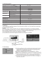
4. Anschlüsse
1) Alle Komponenten gemäß der folgenden Zeichnung korrekt anschließen, um die richtige Polung zu garantieren.
Die folgende Sequenz einhalten:
Achtung:
a) Für den Anschluss zunächst die Batterie, dann das Solarpanel und letztlich die Last am Regler anschließen.
b) Für die Unterbrechung zunächst die Last, dann das Solarpanel und letztlich die Batterie vom Regler trennen.c)
Beim Anschließen der Kabel sicherstellen, dass der Plus- und Minuspol nicht vertauscht sind.
d) Das Batteriekabel nicht am Anschluss des Solarpanels anschließen.
e) Kein stabilisiertes Netzteil oder Ladegerät am Anschluss des Solarpanels anschließen.
5. Statusanzeige
5.1 Mit richtig ausgeführten Anschlüssen wird die korrekte Batteriekapazität durch die
Anzahl der grünen LEDs angezeigt und die Anzeige für die Ausgangsspannung
(POWER OUT in der Abbildung links) leuchtet auf.
5.2 Während des Ladevorgangs leuchten die LEDs zyklisch auf (25 % ~ 100 %).
5.3 Wenn die Batterie vollständig geladen ist, leuchten alle LEDs durchgehend mit Dauerlicht
auf.
5.4 Im Fall einer tiefentladenen Batterie blinkt die LED (25 %) in schnellem Rhythmus, um
den Benutzer darauf hinzuweisen, dass sie schnellstmöglich auszutauschen ist.
5.5 Die Anzeige für die Ausgangsspannung schaltet sich ein oder aus, um anzeigen, ob
letztere aktiv ist oder nicht.
3. Technische Parameter
Nennspannung
Nennstrom
Überlastschutz
Spannung für Wiederaktivierung der Ladung
Modell
ParameTER
Tiefentlade-schutz
Überspannung
Spannungs-einbruch
Deaktivierung
Wiederaktivierung
Deaktivierung
Wiederaktivierung
zwischen Eingang und Batterien
zwischen Batterie und Last
Stromaufnahme ohne Last
Raumtemperatur
Höhe
Abmessungen (LxTxH in mm)
Gewicht (kg)
Temperaturkompensationsfaktor
SPC 10/1
12V
10A
14,4 ± 0,3 Vdc
13,3 ± 0,3 Vdc
11 ± 0,3Vdc
12 ± 0,3 Vdc
17 Vdc
15,0 Vdc
0,5 Vdc
0,2 Vdc
< 5mA
-10
~ +55 °C
5500m
164x100x48
0,39
28
~ 32 mV/Zelle. in °C

7. Anleitung zur Problemlösung
Die Laderegler der Serie HSR12VXX sind von guter Qualität. Im Fall von Problemen oder Störungen die Einheiten
gemäß den folgenden Anleitungen überprüfen oder den Hersteller kontaktieren.
Problem
Ausgangsspannung an.
Die Ladungsanzeige blinkt
Lösung
Die Batterien wurden auf falsche Weise angeschlossen;
den Anschluss korrigieren
6. Schutzfunktion
Schutztyp
Batterieverpolung
Verpolung am Solarmodul
Batteriekreis-unterbrechung
Nähere Beschreibung
Ein akustisches Signal weist darauf hin, dass die Pole vertauscht wurden.
Wenn die Polarität beim Anschluss des Fotovoltaikmoduls nicht berücksichtigt
wird, löst der Schutz des Reglers aus und das Modul funktioniert nicht.
Nach erfolgter Korrektur funktioniert die Einheit ordnungsgemäß.
Wenn der Solarladeregler in Funktion gesetzt ist, die Batterie aber nicht angeschlossen
ist, sorgt der Regler für die Begrenzung der Spannung, damit die Ladung nicht
beeinträchtigt wird.

1. Kenmerken en functies
• Toepassing van de industriestandaard MCU SCM en een speciaal intelligent besturingssoftwareprogramma
• PWM laadregelmodus voor een lading met een hoge efficiëntie
• Beveiliging tegen ompoling van de accu en beveiliging tegen over- en onderspanning.
• Heractivering van uitgaande lading en uitgaande overstroom- en kortsluitbeveiliging
• Beveiliging tegen kortsluiting van het zonnepaneel
• Nullastbeveiliging van de accu
• Spanningsdetectiefunctie met grote precisie
• LED-indicator van de accucapaciteit
2. Algemene inleiding
De zonne-energie laadregelaars van de sc-xa serie, die specifiek volgens de industriestandaard MCU SCM zijn
ontworpen, leveren optimale prestaties en zijn van uitstekende kwaliteit. De regelaars van de sc-xa serie zijn
ontwikkeld voor gebruik in fotovoltaïsche systemen die aan boord van recreatievoertuigen zijn geïnstalleerd.
Functies:
1) Regelfunctie van de accu:
De beveiliging tegen overlading en diepontlading garandeert een goede werking en zorgt voor een langere levensduur
van de accu.
2) Temperatuurcompensatiefunctie:
Regelt automatisch de ingestelde gegevens voor de controleparameters van het besturingsprogramma van de accu
om “onderspanning” van de accu in de winter en “overlading” in de zomer te vermijden.
3) Meerdere beveiligingen:
Beveiliging tegen ompoling van de accu, beveiliging tegen over- en onderspanning en beveiliging tegen kortsluiting
van het zonnepaneel. Automatische herinschakeling van de uitgangsspanning en beveiliging tegen kortsluiting van
de uitgangsspanning.
NL
GEBRUIKSAANWIJZING VOOR DE ZONNE-ENERGIE LAADREGELAAR
(VOOR GEBRUIK AANDACHTIG LEZEN!)

OMVORMER
ACCU
BELASTING
TEMPERATUURSENSOR
4. Aansluitingen
1) Sluit alle onderdelen goed aan op basis van onderstaande tekening om de garantie te hebben dat de polariteit
juist is. De volgorde is als volgt:
Let op:
a) Voor het aansluiten sluit u eerst de accu op de regelaar aan, daarna het zonnepaneel en tot slot de belasting.
b) Voor het loskoppelen, koppelt u eerst de belasting los, daarna het zonnepaneel en tot slot de accu.
c) Tijdens het aansluiten van de kabels moet erop gelet worden dat de “+” en “-” polen niet verwisseld worden.
d) Sluit de accukabel niet aan op de aansluiting van het zonnepaneel.
e) Sluit geen gestabiliseerde voeding of lader aan op de aansluiting van het zonnepaneel.
5. Statusindicatie
5.1 Als de aansluitingen op de juiste manier uitgevoerd zijn, geeft het aantal groene
leds de juiste capaciteit van de accu aan en gaat de indicator van de
uitgangsspanning (POWER OUT op de afbeelding links) branden.
5.2 Tijdens het opladen gaan de leds cyclisch branden (25%~100%).
5.3 Als de accu volledig geladen is blijven alle leds constant branden.
5.4 Als de accu te diep ontladen is knippert de led (25%) snel om de gebruiker te
waarschuwen dat hij de accu zo snel mogelijk moet vervangen.
5.5 De indicator van de uitgangsspanning gaat aan of uit om aan te geven of deze
actief is of niet.
3. Technische parameters
Nominale spanning
Nominale stroom
Beveiliging tegen overlading
Herinschakelspanning van de lading
Modèle nr.
Parameters
Diepontlading
Overspanning
Spanningsdaling
Uitschakelen
Herinschakelen
Uitschakelen
Herinschakelen
Tussen ingang en accu
Tussen accu en lading
Stroomopname zonder belasting
Omgevingstemperatuur
Hoogte
Afmetingen (LxBxH in mm)
Gewicht (kg)
Thermische compensatiefactor
SPC 10/1
12V
10A
14,4 ± 0,3 Vdc
13,3 ± 0,3 Vdc
11 ± 0,3Vdc
12 ± 0,3 Vdc
17 Vdc
15,0 Vdc
0,5 Vdc
0,2 Vdc
< 5mA
-10
~ +55 °C
5500m
164x100x48
0,39
28
- 32 mV/cell. in °C

7. Leidraad voor het oplossen van problemen
De regelaars van de HSR12VXX serie zijn van goede kwaliteit. Controleer in geval van problemen of storingen
de units op basis van de volgende aanwijzingen of neem contact op met de leverancier.
Probleem
De laadindicator knippert
Oplossing
De accu’s zijn verkeerd aangesloten; maak
de aansluiting in orde
6. Beveiligingsfunctie
Soort beveiliging
Ompoling van de accu
Ompoling van de zonne-energie module
Nullast van de accu’s
Details
Een geluidssignaal geeft aan dat de polen verwisseld zijn.
Als het fotovoltaïsche zonnepaneel wordt aangesloten en de polen niet aangehouden
worden, gaat de regelaar op de beveiligingsstand staan en functioneert hij niet.
Wordt dit gecorrigeerd dan zal de unit normaal functioneren.
Als de zonne-energie regelaar in werking is maar de accu niet aangesloten is,
beperkt de regelaar de spanning zodanig dat de belasting beschadigd wordt.

GREAT BRITAIN - SCAN TERIEUR LTD
30, The Metro Centre, Tolpits Lane - Watford,
Herts - England - WD18 9XG
Tel. 01923 800353 - Fax 01923 220358
e-mail: [email protected]
www.scan-terieur.com
THE NETHERLANDS/BELGIUM/LUXEMBOURG/DENMARK/SWEDEN
KARMAN TRADING
Tel. +31 ( 0 ) 341 722450 - Fax +31 ( 0 ) 341 722451
e-mail: [email protected]
www.karmantrading.eu
FRANCE - TELECO SAS
3, impasse des ILES - ZA La Maladière
07300 St Jean de Muzols - France
TéL. 04 75 08 49 17 - Fax 09 70 32 83 00
www.telecogroup.fr
SERVICE COMMERCIAL:
Jean-Philippe Bleys
Tél. 02 48 58 03 67 - Fax. 02 48 58 35 85
Service Technique:
Tél. 06 83 31 44 05 ou 04 75 08 28 25
ESPAÑA - ADD SICMAP S.L.
EVA Caravan - Via Sergia 92
Pol. Ind. Pla d’en Boet II
08302 MATARÓ ( Barcelona )
Tel. 93 790 35 26 - Fax. 93 796 21 17
e-mail: [email protected]
Servicio técnico: Fills de Rocha i Lopez, S.L.
C/Goya, 4 - 08903 L'Hospitalet de Llobregat - Barcelona
Tel. 933 333 753 Fax 933 337 236
ÖSTERREICH - TELECO GmbH
82041 Deisenhofen - Deutschland
Tel. 0049 8031 98939 - Fax. 0049 8031 98949
www.telecogroup.com
SERVICE 0900 94 94 70
DEUTSCHLAND - TELECO GmbH
82041 Deisenhofen
Tel. 08031 98939 - Fax 08031 98949
www.telecogroup.com
Vertretung:
Zimmer - Technik für Mobile Freizeit
Raiffeisenstr. 6 - 64347 Griesheim
Tel. 06155 797873 - Fax 06155 797871
SERVICE 08921129995
Kundendienst bei
ausgewählten
Bosch Service!
Foto e disegni non contrattuali - Les photos et les dessins ne sont donnés qu’à titre indicatif. - We reserve the right to make technical
changes without prior notice -
Fotos und Zeichnungen nicht vertraglich - Foto’s en tekeningen niet contractueel - Fotos y planos no indicados en contrato
IN EUROPE:
SPA
ITALY
Via E. Majorana 49
48022 LUGO ( RA )
Tel. + 39 0545 25037
Fax. + 39 0545 32064
mail: [email protected]
www.telecogroup.com
Assistenza 899 899 856
DEUTSCHLAND
82041 Deisenhofen
Tel. 08031 98939
Fax 08031 98949
www.telecogroup.com
FRANCE
3, Impasse des Iles
ZA La Maladière
07300 St Jean de Muzols
mail: [email protected]
www.telecogroup.fr
ITALY
Via E. Majorana 49
48022 LUGO ( RA )
Tel. + 39 0545 25037
Fax. + 39 0545 32064
mail: [email protected]
www.telecogroup.com
GmbH
sas
srl
06_05_2015
-
 1
1
-
 2
2
-
 3
3
-
 4
4
-
 5
5
-
 6
6
-
 7
7
-
 8
8
-
 9
9
-
 10
10
-
 11
11
-
 12
12
-
 13
13
-
 14
14
-
 15
15
-
 16
16


Teleco TSP 100W regolatore uno Benutzerhandbuch
- Typ
- Benutzerhandbuch
in anderen Sprachen
- français: Teleco TSP 100W regolatore uno Manuel utilisateur
- italiano: Teleco TSP 100W regolatore uno Manuale utente
- Nederlands: Teleco TSP 100W regolatore uno Handleiding
Verwandte Artikel
Andere Dokumente
-
Telair ACB 15A 2out Benutzerhandbuch
-
-
-
 SCS Sentinel AAM0097 Bedienungsanleitung
-
-
-
Phaesun Solar Peak LR1218 120 W Bedienungsanleitung
-
Parkside PWM 4 A1 Operating Instructions Manual
