
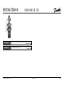
Instructions
6 000 005 867 DEBC 11 / 01
SAIA DN 15 - 50
1 (10)
VI.HA.S1.5B
Safety Pressure Relief Controller (SÜV)
SAIA
ENGLISH
DEUTSCH
www.danfoss.com
Sicherheitsüberströmventil (SÜV)
SAIA
www.iwk.danfoss.de
www.danfoss.de

2
SAIA
ENGLISH
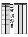
Contents
Safety Notes 3
Definition of
Application 3
Installation 4
- Admissible Installa-
tion Position 4
- Installation Scheme 4
- Valve Installation 5
- Insulation 6
- Dimensions, Weights 6
Start up 7
- Filling the System,
First Start-up 7
- Putting out of
Operation 7
- Leak and Pressure
Test 8
- Setpoint Adjustment 9
- Safety Function 10
DEUTSCH
Inhalt
Sicherheitshinweise 3
Bestimmungsgemäße
Verwendung 3
Montage 4
- Zulässige
Einbaulagen 4
- Einbauschema 4
- Einbau Ventil 5
- Isolierung 6
- Abmessungen,
Gewichte 6
Inbetriebnahme 7
- Füllung der Anlage,
Inbetriebnahme 7
- Außerbetriebnahme 7
- Dichtheits-,
Druckprüfung 8
- Sollwerteinstellung 9
- Sicherheitsfunktion 10

3
SAIA
ENGLISH
Safety Notes
To avoid injury of persons
and damages to the
device, it is absolutely
necessary to observe these
Instructions.
Necessary assembly, start-
up, and maintenance work
may be performed only by
qualified and authorized
personnel.
Prior to assembly and
disassembly, depressurize
system!
Please comply with the
instructions of the system
manufacturer or system
operator.
Definition
of Application
The controller is designed
for pressure control and as
a protection against excess
pressure in front of the
valve.
This device is used for
water control in heating and
district heating systems.
The technical data on the
rating plates determine the
use.
DEUTSCH
Sicherheitshinweise
Um Verletzungen an Perso-
nen und Schäden am Gerät
zu vermeiden, diese Anlei-
tung unbedingt beachten.
Montage, Inbetriebnahme
und Wartungsarbeiten
dürfen nur von sach-
kundigen und autorisierten
Personen durchgeführt
werden.
Anlage vor Montage,
Demontage unbedingt
drucklos machen!
Die Vorgaben des Anlagen-
herstellers und Anlagen-
betreibers sind zu
beachten.
Bestimmungsgemäße
Verwendung
Der Regler dient der
Druckregelung und der
Absicherung gegen
Überschreitung des
Druckes vor dem Ventil.
Der Regler wird in
Heizungs- und
Fernheizungsanlagen für
das Medium Wasser
eingesetzt.
Die technischen Daten auf
den Typenschildern sind für
den Einsatz maßgebend.

4
SAIA
ENGLISH DEUTSCH
Montage
Zulässige Einbaulagen
Mediumstemperaturen
bis 100 °C:
Einbaulage beliebig
Mediumstemperaturen
größer 100 °C:
Einbau nur in waagrechte
Rohrleitung mit nach unten
hängendem Antrieb
zulässig.
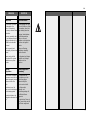
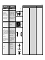
Einbauschema
Die Absperrarmatur
➀
gegen unbefugtes
Schließen sichern.
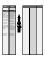
Installation
Admissible Installation
Positions
Medium temperatures
up to 100 °C:
Can be installed in any
position
Medium temperatures
>100 °C
Installation only permitted
in horizontal pipelines,
with the actuator hanging
downwards.
Installation Scheme
Secure the shut-off unit
➀
against unauthorized
opening.
SAID
➀
SAIA

5
SAIA
DEUTSCH
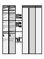
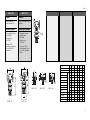
Einbau Ventil
1.Schmutzfänger ➀ vor
dem Regler einbauen.
Max. Maschenweite
DN 15 - 25: 0,5 mm
DN 32 - 50: 0,8 mm
2.Anlage vor dem Einbau
des Ventils spülen.
3.Durchflussrichtung ➁
auf dem Typenschild
beachten.
Ausführung mit Flanschen:
Flansche
➂ in der Rohr-
leitung müssen parallel,
Dichtflächen sauber und
ohne Beschädigung sein.
4.Ventil einbauen.
5.Schrauben über Kreuz
in 3 Stufen bis zum
max. Drehmoment
anziehen.
Ausführung mit
Schweißenden:
➃ nur heften
➄ schweißen
ENGLISH
Valve Installation
1.Install strainer ➀ before
the controller.
Max. mesh width
DN 15 - 25: 0.5 mm
DN 32 - 50: 0.8 mm
2.Rinse system prior to
installing the valve.
3.Observe flow direction
➁ on the rating plate.
Design with flanges:
Flanges
➂ in the pipeline
must be in parallel position
and sealing surfaces must
be clean and without any
damage.
4.Install valve.
5.Tighten screws cross-
wise in 3 steps up to the
max. torque.
Design with welded ends:
➃ Pin only
➄ Weld
➂
➁
➄
➀
➃
SAIA
SAID

6
SAIA
ENGLISH
Insulation
Do not insulate the
pressure actuator
➀ .
Dimensions, Weights
1)
Conic male thread acc.
to DIN 2999
2)
Thread acc. to
ISO 228/1
3)
Flange PN 25:
connection dimension
acc. to DIN 2501,
seal form C
DEUTSCH
Isolierung
Den Druckantrieb
➀ nicht
isolieren.
Abmessungen, Gewichte
1)
Kegeliges Aussen-
gewinde nach
DIN 2999
2)
Gewinde nach
ISO 228/1
3)
Flansche PN 25:
Anschlussmaße nach
DIN 2501, Dichtleiste
Form C
L
2
SW
G
E
S
SW
R
L
1
DN 32 - 50
DN 15 - 50
DN 15 - 50
DN 15 - 25
DN 15 - 25
➀
DN 15 20 25 32 40 50
R
1)
R 1/2 R 3/4 R 1 - - -
G
2)
3/4 A 1 A 1 1/4 A - - -
s 8.5 10 11 - - -
SW 32 41 50 - - -
d212633---
E657075---
L mm 139 154 159 184 204 -
L1 125 146 169 - - -
L2
3)
130 150 160 180 200 230
H1 57 64 64 57 62 62
H2 (1-5 bar) mm 270 276 276 306 310 310
Weight kg 5.2
4)
5.5
4)
5.7
4)
10.7 13.2 14.2
H2 (3-12 bar) mm 330 336 336 336 370 370
Weight kg 6.7
4)
7.0
4)
7.2
4)
12.2 14.7 15.7

7
SAIA
ENGLISH
Start Up
Filling the System, First
Start-up
Note
The valve is closed without
pressure.
The valve is opening
when the pressure in front
of the valve
➀
rises above
the adjusted setpoint.
1. Slowly open shut-off unit
➁ (outlet).
2. Slowly open shut-off unit
➂ (inlet).
Putting out of Operation
1. Slowly close shut-off
unit ➂ (inlet).
2. Slowly close shut-off
unit
➁ (outlet).
DEUTSCH
Inbetriebnahme
Füllung der Anlage,
Inbetriebnahme
Hinweis
Das Ventil ist drucklos
geschlossen.
Das Ventil öffnet, wenn der
Druck vor dem
Ventil
➀
über den
eingestellten Sollwert
steigt
1. Zuerst Absperrarmatur
➁ (Ausgang) langsam
öffnen.
2. Absperrarmatur ➂
(Eingang) langsam
öffnen.
Außerbetriebnahme
1. Absperrarmatur ➂
(Eingang) langsam
schließen.
2. Absperrarmatur ➁
(Ausgang) langsam
schließen.
➀
➁
➂

8
SAIA
DEUTSCH
Dichtheits-,
Druckprüfung
Bei Dichtheits-,
Druckprüfungen beachten:
Das Ventil ist drucklos
geschlossen.
Das Ventil öffnet, wenn der
Druck ➀ vor dem Ventil
über den eingestellten
Sollwert steigt
Daher den Druck
möglichst von allen Seiten
gleichmässig erhöhen.
Bei Prüfdrücken größer
14 bar:
- die Steuerleitung
➁
unbedingt entfernen
- den Anschluss
➂ mit
Stopfen G 1/8 ISO 228
schließen
Das Ventil ist in diesem
Fall immer geschlossen.
⇒ unbedingt den Druck
von allen Seiten
gleichmässig erhöhen
Max. Prüfdruck ist
1,5 x PN 25 = 37,5 bar
ENGLISH
Leak and Pressure Tests
When testing tightness and
pressure:
The valve is closed without
pressure.
The valve is opening
when the pressure ➀ in
front of the valve rises
above the adjusted
setpoint.
Therefore, increase
pressure only
simultaneously at all sides.
With pressures above
14 bar
- It is absolutely
necessary to remove
the impulse tube
➁.
- Close connection
➂
with plug G 1/8 ISO 228.
In this case, the valve is
always closed.
⇒ increase pressure only
simultaneously at all
sides.
Max testing pressure is
1.5 * PN 25 = 37.5 bar
➁
➀
➂

9
SAIA
DEUTSCH
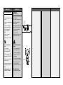
Sollwerteinstellung
Sollwertbereich siehe
Typenschild
➀.
1.Einstellung des Druckes
➁ vor dem Regler
SAIA:
Rechtsdrehung ➂
erhöht den Sollwert.
(Feder spannen,
Druckfeder)
Linksdrehung ➃
reduziert den Sollwert.
(Feder entspannen)
3.Der Sollwertsteller ➄
kann plombiert werden.
ENGLISH
Setpoint Adjustment
Set-point range see rating
plate
➀.
1.Adjustment of the
pressure ➁ in front
of the valve SAIA:
Turning to the right ➂
increases the set-point
(stressing the spring,
tension spring)
Turning to the left ➃
reduces the set-point
(unstressing the spring)
3.The set-point adjuster ➄
may be sealed.
➂
➃
➄
+
0
bar
0
bar
-
➁
SAIA
➀
Danfoss SAIA
Code Nr. 065-4278
p
s
(bar) 1 - 4,5

10
SAIA
DEUTSCH
Sicherheitsfunktion
Bei einem Membranbruch
der Regelmembrane
➀
wird in den beiden
Zwischenkammern ➁ ein
Druck aufgebaut. Der
Druck wirkt auf die
Sicherheitsmembrane ➂
dadurch wird:
- das Ventil geöffnet
- die Regelfunktion ist
außer Betrieb
- Anzeige des Membran-
bruchs durch geringen
Wasseraustritt an der
Verschraubung
➃
Der Regler muss nach
einem Membranbruch
ausgetauscht werden.
ENGLISH
Safety function
If the control diaphragm
➀
breaks, pressure is
developped in the two
intermediate chambers ➁.
This pressure acts upon
the safety diaphragm ➂
and causes the following:
- The valve is opened.
- The control function
does not operate.
- A slight water leakage
at the threaded joint
➃
indicates a break of the
diaphragm.
The controller must be
replaced when the
diaphragm is broken.
➀
➁
➂
➃
-
 1
1
-
 2
2
-
 3
3
-
 4
4
-
 5
5
-
 6
6
-
 7
7
-
 8
8
-
 9
9
-
 10
10


in anderen Sprachen
- English: Danfoss SAIA Operating instructions
Verwandte Artikel
-
Danfoss SAID Bedienungsanleitung
-
-
-
-
-
-
-
-