SICK Analog module BAM100 Bedienungsanleitung
- Typ
- Bedienungsanleitung

Analogmodul BAM100 /
Analog module BAM100
Zur Erstinformation. Dokument ersetzt nicht die Betriebsanleitung!
For detailed information, please refer to the operation manual.
Irrtümer und Änderungen vorbehalten · Subject to change without notice
GERÄTEHINWEIS
NOTES ON DEVICE
DE
Sicherheitshinweise
Setzen Sie das Busklemmen-
System in einen sicheren,
spannungslosen Zustand,bevor
Sie mit der Montage, Demontage
oder Verdrahtung der Busklem-
men beginnen!
Montage
Die Buskoppler und Busklem-
men werden durch leichten
Druck auf handelsübliche
35 mm Tragschienen (Hutschie-
nen nach EN 50022) aufgeras-
tet: Achten Sie bei der Montage
der Busklemmen darauf, dass
der Verriegelungsmechanismus
der Klemmen nicht in Konikt
mit den Befestigungsschrauben
der Tragschiene gerät.
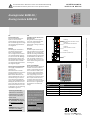
Spannungsversorgung BC9050
Versorgung von Busklemmen
Controller (Us)
Der Busklemmen Controller
benötigt zum Betrieb eine Versor-
gungsspannung von 24 V
DC
.
Der Anschluss ndet über die
oberen Federkraftklemmen mit
der Bezeichnung 24 V und 0 V
statt. Diese Versorgungsspan-
nung versorgt die Elektronik der
Buskoppler / Busklemmen-Con-
troller sowie über den K-Bus die
Elektronik der Busklemmen. Sie
ist galvanisch von der Spannung
der Feldebene getrennt.
EN
Installation of Bus Terminals on
mounting rails
Bring the bus terminal system
into a safe, powered down state
before starting installation,
disassembly or wiring of the Bus
Terminals!
Assembly
The Bus Coupler and Bus Termi-
nals are attached to commercially
available 35 mm mounting rails
(DIN rails according to EN 50022)
by applying slight pressure:During
the installation of the Bus Termi-
nals, the locking mechanism of
the terminals must not come into
conict with the xing bolts of the
mounting rail.
Power supply BC9050
Bus Terminal Controller supply (Us)
The Bus Terminal Controller re-
quires a supply voltage of 24 V
DC.
The connection is made by me-
ans of the upper spring-loaded
terminals labelled 24 V and 0 V.
This supply voltage is used for
the electronic components of the
Bus Coupler and Bus Terminal
Controllers and (via the K-bus)
the electronic components of the
Bus Terminals. It is galvanically
separated from the eld level
voltage.
24V
1
2
3
4
5
6
7
8
OV
++
--
PE
BC9050
PE
Feeding
Bus Terminal Controller +24 V
DC
Feeding
Bus Terminal Controller OV
Feeding
Power Contacts +24 V
DC
Feeding
Power Contacts O V
n.c.
Reihenfolge Bezeichnung
Order Marking
1 BC9050 (Buscontroller)
2 KL3454 (4x Analog Input)
3 KL4424 (4x Analog Output)
4 KL9010 (Endklemme / end terminal)
1 2 3 4
For instructions on mount-
ing, electrical installation,
start-up, conguration as
well as for technical data
please refer to:
Operating Instructions
(part no. 8014829, Eng-
lish edition) on www.sick.
com/Bulkscan
SOPAS ET software on
www.sick.com/SOPAS
Anleitung zur Montage,
elektrischem Anschluss,
Inbetrieb nahme, Kongu-
ration sowie technische
Daten siehe:
Betriebsanleitung (Artikel-
Nr. 8014828, dt. Ausgabe)
auf www.sick.com/Bulk-
scan
SOPAS ET Software unter
www.sick.com/SOPAS

8016795/11NT/2018-11-08 · 9MS · VD · Printed in Germany
· Irrtümer und Änderungen vorbehalten · Subject to change without notice · Aftint48sw
SICK AG | Waldkirch | Germany | www.sick.com
Elektroinstallation / Electrical installation
Analogmodul BAM100 / Analog module BAM100
DE
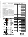
Eingänge KL3454
(siehe Tabelle 1 und Grak 1)
Die analoge Eingangsklemme
KL3454 verarbeitet Signale im
Bereich von 4 bis 20 mA. Der
Strom wird mit einer Auösung von
12 Bit digitalisiert und galvanisch
getrennt zum übergeordneten Au-
tomatisierungsgerät transportiert.
Bei der Busklemme KL3454 sind
die vier Eingänge in Zweileitertech-
nik ausgeführt und besitzen ein
gemeinsames Massepotenzial.
Ausgänge KL4424
(siehe Tabelle 2 und Grak 2)
Die analoge Ausgangsklemme
KL4424 erzeugt Signale im Be-
reich von 4…20 mA. Der Strom
wird mit einer Auösung von 12 Bit
galvanisch getrennt zur Prozesse-
bene gespeist. Die Ausgangsstufe
wird durch die 24 V Versorgung
gespeist. Die Busklemme besitzt
ein gemeinsames Massepotenzi-
al. Die Powerkontakte sind durch-
verbunden; die Bezugsmasse der
Ausgänge ist der Powerkontakt 0
V. Die Leuchtdioden zeigen den
Datenaustausch mit dem Bus-
koppler an.
Klemmstelle Nr. Kanal Name Anschluss für
Terminal point nr. Channel Name Connection for
1 1 Input 1 Analogeingang 1, Bandge-
schwindigkeit (4…20 mA)
Analog input 1, belt speed
(4...20 mA)
2 +24 V Analogeingang 1, 24 V
Analog input 1, 24 V
3 3 Input 3 Analogeingang 3, Massen-
strom (4…20 mA)
Analog input 3, mass ow
rate (4...20 mA)
4 +24 V Analogeingang 3, 24 V
Analog input 3, 24 V
5 2 Input 2 Analogeingang 2, Schütt-
gutdichte (4…20 mA)
Analog input 2, bulk densi-
ty (4...20 mA)
6 +24 V Analogeingang 2, 24 V
Analog input 2, 24 V
7 4 Input 4 Analogeingang 4, Externer
Eingang (4… 20 mA)
Analog input 4, external
input (4… 20 mA)
8 +24 V Analogeingang 4, 24 V
Analog input 4, 24 V
LED Run 1
LED Error 1
LED Run 3
LED Error 3
LED Run 2
LED Error 2
LED Run 4
LED Error 4
Input 2
Input 1
Input 3
Power-
contacts
+24 V
+24 V
13
E1 E2
++
++
E3 E4
14
KL3454
1
2
3
4
5
6
7
8
Input 4
Run 1
Run 3
Run 2
Run 4
Output 2
Output 1
Output 3
Power-
contacts
0 V0 V
0 V
13
A1 A2
--
--
A3 A4
14
KL4424
1
2
3
4
5
Output 4
7
6
0 V
8
Klemmstelle Nr. Kanal Name Anschluss für
Terminal point nr. Channel Name Connection for
1 1 Output
1
Analogausgang 1, Signal
(4… 20 mA)
Analog output 1, signal
(4… 20 mA)
2 0 V Analogausgang 1, Masse
Analog output 1, ground
3 3 Output
3
Analogausgang 3, Signal
(4… 20 mA)
Analog output 3, Signal
(4… 20 mA)
4 0 V Analogausgang 3, Masse
Analog output 3, ground
5 2 Output
2
Analogausgang 2, Signal
(4… 20 mA)
Analog output 2, signal
(4… 20 mA)
6 0 V Analogausgang 2, Masse
Analog output 2, ground
7 4 Output
4
Analogausgang 4, Signal
(4… 20 mA)
Analog output 4, signal
(4… 20 mA)
8 0 V Analogausgang 4, Masse
Analog output 4, ground
EN
Analog input terminal KL3454
(see table 1 an g. 1))
The KL3454 analog input terminal
process signals in the range bet-
ween 4 and 20 mA. The current
is digitized to a resolution of 12
bits, and is transmitted, in an
electrically isolated form, to the
higher-level automation device.
In the KL3454 Bus Terminal, the
four inputs are 2-wire versions and
have a common ground potential.
Analog output KL4424
(see table 2 and g. 2)
The KL4424 analog output ter-
minal generates signals in the
range 4 ... 20 mA. The power is
supplied to the process level with
a resolution of 12 bits, and is elec-
trically isolated. The output stage
is powered by the 24 V supply. The
terminals four outputs are 2-wire
versions and have a common
ground potential. The power con-
tacts are connected through. The
reference ground of the outputs is
the 0 V power contact. The LEDs
indicate the data exchange with
the Bus Coupler.
Tabelle 1 / table 1
Tabelle Nr. 2 / table 2
Grak 1 / g. 1
Grak 2 / g. 2
-
 1
1
-
 2
2


SICK Analog module BAM100 Bedienungsanleitung
- Typ
- Bedienungsanleitung
in anderen Sprachen
Andere Dokumente
-
WAGO INTERBUS ECO Fieldbus Coupler Benutzerhandbuch
-
-
-
-
-
-
-
-
-
IFM AC3218 Bedienungsanleitung