janitza 800-CT8-LP Installationsanleitung
- Kategorie
- Messung
- Typ
- Installationsanleitung

1 / 10
Allgemeines
12
Janitza electronics GmbH
Vor dem Polstück 6
D-35633 Lahnau
Support Tel. +49 6441 9642-22
E-Mail: [email protected]
www.janitza.de
www.janitza.de
Dok Nr. 2.053.114.0.d Stand: 05/2023
Modul 800-CT8-LP
Strommessmodul für das UMG 801
Installationsanleitung
English version:
see rear side
2Sicherheit
Haftungsausschluss
Die Beachtung der Nutzungsinformationen zu
den Geräten, Modulen und Komponenten ist
Voraussetzung für den sicheren Betrieb und um
angegebene Leistungsmerkmale und Produktei-
genschaften zu erreichen. Für Personen-, Sach-
oder Vermögensschäden, die durch Nichtachtung
der Nutzungsinformationen entstehen, übernimmt
die Janitza electronics GmbH keine Haftung. Sor-
gen Sie dafür, dass Ihre Nutzungsinformationen
leserlich zugänglich sind.
Weiterführende Nutzungsinformationen, wie
z.B. die Installationsanleitung oder das Benut-
zerhandbuch zum Basisgerät, finden Sie auf
unserer Website www.janitza.de unter Support >
Downloads.
Urheberrechtsvermerk
© 2023 - Janitza electronics GmbH - Lahnau.
Alle Rechte vorbehalten. Jede, auch auszugswei-
se, Vervielfältigung, Bearbeitung, Verbreitung und
sonstige Verwertung ist verboten.
Technische Änderungen vorbehalten
• Achten Sie darauf, dass Ihr Gerät, Modul oder
Ihre Komponente mit der Installationsanleitung
übereinstimmt.
• Lesen und verstehen Sie zunächst produktbe-
gleitende Nutzungsinformationen.
• Produktbegleitende Nutzungsinformationen
während der gesamten Lebensdauer verfügbar
halten und gegebenenfalls an nachfolgende
Benutzer weitergeben.
• Bitte informieren Sie sich über Geräte-Revisio-
nen und die damit verbundenen Anpassungen
der produktbegleitenden Nutzungsinformationen
auf www.janitza.de.
Entsorgung
Bitte beachten Sie nationale Bestimmungen! Ent-
sorgen Sie gegebenenfalls einzelne Teile, je nach
Beschaffenheit und existierende länderspezifische
Vorschriften, z.B. als:
• Elektroschrott
• Batterien und Akkumulatoren
• Kunststoffe
• Metalle
oder beauftragen Sie einen zertifizierten
Entsorgungsbetrieb mit der Verschrottung.
3
9
Benutzerhandbuch:
Das Strommessmodul
· erweitert den Funktionsumfang des Basisgeräts um weitere Strommesskanä-
le (2Gruppen á 4 Strommesskanäle).
· eignet sich für Low-Power-Stromwandler (LP-Stromwandler) mit den Wand-
lerverhältnissen von .. /0-400mV.
Das Basisgerät (UMG 801)
· erlaubt die Montage von bis zu 10 Strommessmodulen des Typs 800-CT8-LP.
· mit Strommessmodul misst Strom ausschließlich über LP-Stromwandler. Die
LP-Stromwandler benötigen eine durchgängig doppelte Isolierung gemäß IEC
61010-1:2010 zu Netz- oder Messstromkreisen.
Geräte-Kurzbeschreibung
6 7 8 Demontage
Busverbinder-
Kontakte
Schraubendreher
zur Entriegelung
Busverbinder-
Buchsen
Bodenriegel
ACHTUNG
Zu grobe Handhabung kann Ihr Modul beschädi-
gen und zum Sachschaden führen!
Die Busverbinder-Kontakte und die Bodenriegel
können bei der Demontage Ihres Moduls beschädigt
oder abgebrochen werden.
· Entreißen Sie niemals mit Gewalt das Modul
der Hutschiene.
· Entkoppeln Sie zuvor die Busverbinder (Jan-
Bus-Schnittstelle) und entriegeln Sie achtsam
mit dem Schraubendreher die Bodenriegel des
Moduls!
Modul demontieren:
1. Anlage spannungsfrei schalten! Gegen Wieder-
einschalten sichern! Spannungsfreiheit fest-
stellen! Erden und Kurzschließen! Benachbarte,
unter Spannung stehende Teile abdecken oder
abschranken!
2. Lösen Sie die Verdrahtung Ihres Moduls.
3. Entkoppeln Sie die Busverbinder (JanBus-
Schnittstelle) Ihres Moduls vom Basisgerät und/
oder den angereihten Modulen durch herauszie-
hen Ihres Moduls.
4. Entriegeln Sie alle Bodenriegel Ihres Moduls.
Empfehlung: Verwenden Sie hierfür einen
Schraubendreher (Achtsam!).
5. Entnehmen Sie Ihr Modul der Hutschiene ohne
die Busverbinder-Kontakte zu berühren oder zu
beschädigen.
Bus-
verbinder-
Buchsen
JanBus-
Schnittstelle
Hutschiene
JanBus-
Schnittstelle
für weitere
Module
ACHTUNG
Sachschaden durch Demontieren oder Entkoppeln
des Moduls während des Betriebs!
Demontieren oder Entkoppeln des Moduls während der
Kommunikation mit dem Basisgerät kann zur Beschä-
digung Ihrer Geräte führen!
· Schalten Sie vor der Demontage oder Entkop-
pelung des Moduls Ihre Anlage spannungsfrei!
Sichern Sie gegen Wiedereinschalten! Span-
nungsfreiheit feststellen! Erden und Kurzschlie-
ßen! Benachbarte, unter Spannung stehende Teile
abdecken oder abschranken!
Technische Daten
Allgemein
Nettogewicht
(mit Steckklemmen) 73g (0.16lb)
Geräteabmessungen B=18mm
(0.
71
in)
, H=90mm (3.54
in), T=76mm (2.99in)
Einbaulage beliebig
Befestigung/Montage -
geeignete Hutschienen
(35mm)
· TS 35/7,5 nach EN60715
· TS 35/10
· TS 35/15 x 1,5
Schutzart IP20 nach EN60529
Schlagfestigkeit IK07 nach IEC 62262
Strommessung Modul 800-CT8-LP
Messung über Low-Power-Strom-
wandler mit einer Sekundärspan-
nung von
.. / 0-400mV
Kanäle 8 (2x4)
· 2 Systeme (L1, L2, L3, N)
· Einzelkanäle
Eingangsimpedanz pro Kanal 230kΩ
Nenneingangssignal des Moduls 0 ... 400mV
Crest-Faktor 1,8
Überlast für 1 s 1V
Auflösung 16 Bit
Abtastfrequenz 6,8kHz
Frequenz der
Grundschwingung 40Hz .. 70Hz
Harmonische 1..15. (nur ungerade)
Transport und Lagerung
Die folgenden Angaben gelten für in der Originalverpackung
transportierte und gelagerte Geräte
Freier Fall 1m (39.37in)
Temperatur K55 -
-25°C(-13°F) bis +70°C(158°F)
Relative Luftfeuchtigkeit 0 bis 95% bei 25°C (77°F)
ohne Kondensation
Schnittstelle und Energieversorgung
JanBus (proprietär) · Über Busverbinder
· Max. Buslänge (JanBus) 100m
Versorgungsspannung
(über JanBus-Schnittstelle) 24V
Art. Nr. 3303892
LEDs Modul 800-CT8-LP
Tx (Daten senden) Blinken „orange“ im Betrieb und
signalisieren zyklischen Datenaus-
tausch.
Rx (Daten empfangen)
P (Power - Spannungs-
versorgung)
Leuchtet „grün“ bei korrekter Span-
nungsversorgung über die JanBus-
Schnittstelle.
E (Error - Initialisierung
und Fehlerfall) Leuchtet „rot“ bei der Initialisierung/
Start des Geräts und im Fehlerfall.
Umgebungsbedingungen im Betrieb
Das Gerät
· wettergeschützt und ortsfest einsetzen.
· erfüllt die Einsatzbedingungen nach DIN IEC 60721-3-3.
· besitzt Schutzklasse II nach IEC 60536 (VDE 0106, Teil 1), ein
Schutzleiteranschluss ist nicht erforderlich!
Arbeitstemperatur -10°C(14°F) .. +55°C(131°F)
Relative Luftfeuchtigkeit
im Betrieb 5 bis 95 % bei 25 °C (77 °F) ohne
Kondensation
Verschmutzungsgrad 2
Belüftung Keine Fremdbelüftung erforderlich
Versorgungsspannung Über Basisgerät UMG801
Anschlussvermögen der Klemmstellen - Modul
800-CT8-LP
Anschließbare Leiter
Pro Klemmstelle nur einen Leiter anschließen!
Eindrähtige, mehrdrähti-
ge, feindrähtige 0,2 - 1,5mm2, AWG 24-16
Aderendhülsen (nicht
isoliert) 0,2 - 1,5mm2, AWG 26-16
Aderendhülsen (isoliert) 0,2 - 1mm2, AWG 26-18
Aderendhülsen:
Länge der Kontakthülse 7mm (0.2756 in)
Anzugsdrehmoment
Schraubflansch 0,2 - 0,25 Nm (1.77 - 2.21 lbf in)
Relevante Gesetze,
angewendete Normen und Richtlinien
Die von der Janitza electronics GmbH angewen-
deten Gesetze, Normen und Richtlinien für das
Gerät entnehmen Sie der Konformitätserklärung
auf unserer Website (www.janitza.de).
INFORMATION
Unsere Nutzungsinformationen verwenden die nach
der Grammatik männliche Form im geschlechtsneu-
tralen Sinne! Sie sprechen immer Frauen, Männer
und Diverse an. Um Texte leichter lesbar zu halten,
wird auf Unterscheidungen verzichtet. Wir bitten um
Verständnis für diese Vereinfachungen.
Sicherheitshinweise
Die Installationsanleitung stellt kein vollständi-
ges Verzeichnis aller für den Betrieb des Geräts
(Modul/Komponente) erforderlichen Sicherheits-
maßnahmen dar.
Besondere Betriebsbedingungen können weitere
Maßnahmen erfordern. Die Installationsanleitung
enthält Hinweise, die Sie zu Ihrer persönlichen
Sicherheit und zur Vermeidung von Sachschäden
beachten müssen.
Verwendete Symbole auf dem Gerät (Modul/
Komponente):
Das zusätzliche Symbol auf dem
Gerät selbst deutet auf eine elekt-
rische Gefahr hin, die zu schweren
Verletzungen oder Tod führen kann.
Das allgemeine Warnsymbol macht
Sie auf mögliche Verletzungsge-
fahren aufmerksam. Beachten Sie
alle unter diesem Symbol aufge-
führten Hinweise, um mögliche
Verletzungen oder gar Todesfälle
zu vermeiden.
Sicherheitshinweise in der Installationsanleitung
sind durch ein Warndreieck hervorgehoben und je
nach Gefährdungsgrad wie folgt dargestellt:
ACHTUNG
Warnt vor einer unmittelbar gefährlichen Situation,
die bei Nichtbeachtung zu Sachschäden oder
Umweltschäden führen kann.
GEFAHR
Warnt vor einer unmittelbar drohenden Gefahr, die
zu schweren bzw. tödlichen Verletzungen oder Tod
führt.
VORSICHT
Warnt vor einer möglicherweise gefährlichen Situati-
on, die zu geringfügigen oder mäßigen Verletzungen
führen kann.
WARNUNG
Warnt vor einer möglicherweise gefährlichen Situa-
tion, die zu schweren Verletzungen oder Tod führen
kann.
INFORMATION
Verweist auf Vorgänge bei denen keine Gefahr von
Personen- oder Sachschäden besteht.
Maßnahmen zur Sicherheit
Beim Betrieb elektrischer Geräte stehen zwangs-
läufig bestimmte Teile dieser Geräte und deren
Komponenten unter gefährlicher Spannung. Es
können deshalb schwere Körperverletzungen
oder Sachschäden auftreten, wenn nicht fachge-
recht gehandelt wird:
• Vor Anschluss von Verbindungen das Gerät
und dessen Komponenten, am Schutzleiter-
anschluss, wenn vorhanden, erden.
• Gefährliche Spannungen können in allen
mit der Spannungsversorgung verbundenen
Schaltungsteilen anstehen.
• Auch nach Abtrennen der Versorgungsspan-
nung können gefährliche Spannungen im
Gerät oder den Komponenten vorhanden sein
(Kondensatorspeicher).
• Betriebsmittel mit Stromwandlerkreisen nicht
offen betreiben.
• Die im Benutzerhandbuch und auf dem
Typenschild genannten Grenzwerte nicht
überschreiten! Dies ist auch bei der Prüfung
und der Inbetriebnahme zu beachten!
• Beachten Sie Sicherheits- und Warnhinweise
in den Nutzungsinformationen, die zu den
Geräten und deren Komponenten gehören!
Qualifiziertes Personal
Um Personen- und Sachschäden zu vermeiden,
darf nur qualifiziertes Personal mit elektrotech-
nischer Ausbildung am Basisgerät und dessen
Komponenten arbeiten mit Kenntnissen
• der nationalen Unfallverhütungsvorschriften.
• in Standards der Sicherheitstechnik.
• in Installation, Inbetriebnahme und Betrieb
des Geräts und der Komponenten.
Bestimmungsgemäße Verwendung
Die Module/Komponenten
• sind nur für den Einsatz im Bereich der indust-
riellen Steuerungen bestimmt.
• sind als Erweiterungs- oder Übergabemodule
für das Basisgerät UMG 801 in Schaltschrän-
ken und Installationskleinverteilern bestimmt.
Bitte beachten Sie die zum Basisgerät gehö-
renden Nutzungsinformationen.
• nur mit spannungsfrei geschaltetem Basisgerät
montieren (siehe Schritt „Montage“).
• sind nicht für den Einbau in Fahrzeuge
bestimmt! Der Einsatz des Basisgeräts mit Mo-
dulen in nicht ortsfesten Ausrüstungen gilt als
außergewöhnliche Umweltbedingung und ist
nur nach gesonderter Vereinbarung zulässig.
• sind nicht für den Einbau in Umgebungen mit
schädlichen Ölen, Säuren, Gasen, Dämpfen,
Stäuben, Strahlungen, usw. bestimmt.
WARNUNG
Verletzungsgefahr durch elektrische Spannung
oder elektrischen Strom!
Im Umgang mit elektrischen Strömen oder Span-
nungen können schwere Körperverletzungen oder
Tod erfolgen durch:
· Berühren von blanken oder abisolierten Adern,
die unter Spannung stehen.
· Berührungsgefährliche Eingänge des Geräts.
Vor Arbeitsbeginn an Ihrer Anlage:
· Die Anlage spannungsfrei schalten!
· Gegen Wiedereinschalten sichern!
· Spannungsfreiheit feststellen!
· Erden und Kurzschließen!
· Benachbarte, unter Spannung stehende Teile
abdecken oder abschranken!
Eingangskontrolle
Der einwandfreie und sichere Betrieb der Geräte,
Module und Komponenten setzen sachgemäßen
Transport, fachgerechte Lagerung, Aufstellung
und Montage sowie sorgfältige Bedienung und
Instandhaltung voraus.
Nehmen Sie das Aus- und Einpacken mit der
üblichen Sorgfalt ohne Gewaltanwendung und nur
unter Verwendung von geeignetem Werkzeug vor.
Prüfen Sie:
• Geräte, Module und Komponenten durch
Sichtkontrolle auf einwandfreien mechani-
schen Zustand.
• den Lieferumfang (siehe Benutzerhandbuch)
auf Vollständigkeit bevor Sie mit der Installa-
tion Ihrer Geräte, Module und Komponenten
beginnen.
Wenn anzunehmen ist, dass ein gefahrloser
Betrieb nicht mehr möglich ist, so setzen Sie Ihr
Gerät, Modul oder Ihre Komponente unverzüglich
außer Betrieb! Sichern Sie gegen unbeabsichtigte
Inbetriebnahme.
Es ist anzunehmen, dass ein gefahrloser Betrieb
unmöglich ist, wenn das Basisgerät, das Modul
oder die Komponente z.B.:
• sichtbare Beschädigungen aufweist.
• trotz intakter Netzversorgung nicht mehr
arbeitet.
• längere Zeit ungünstigen Verhältnissen (z.B.
Lagerung außerhalb der zulässigen Klimagren-
zen ohne Anpassung an das Raumklima, Be-
tauung o.Ä.) oder Transportbeanspruchungen
(z.B. Fall aus großer Höhe auch ohne sichtbare
äußere Beschädigung o.Ä.) ausgesetzt war.
Modul 800-CT8-LP.
INFORMATION
· Der Lieferumfang des Moduls beinhaltet den passenden Busverbinder (JanBus-
Schnittstelle) zum Anschluss an das Basisgerät oder weiterer Module!
· Beachten Sie zusätzlich zum Strommessmodul auch die Nutzungsinformationen
Ihres Basisgeräts und der LP-Stromwandler!
· Anschlussleitungen der LP-Stromwandler an den Strommesseingängen des
Geräts/Moduls nicht verlängern! Verlängerte Messleitungen können das Messer-
gebnis beeinflussen!
Montage
4
WARNUNG
Sach- oder Personenschaden durch Nichtbe-
achtung der Montagehinweise!
Nichtbeachtung der Montagehinweise kann Ihr
Basisgerät mit Modul beschädigen oder zerstören
und bis hin zu Personenschäden führen.
· Beachten Sie neben den Montagehinweisen
Ihres Moduls auch die Montagehinweise Ihres
Basisgeräts, insbesondere Sicherheits- und
Warnhinweise.
· Vor der Montage von Modulen
- Anlage spannungsfrei schalten!
-Gegen Wiedereinschalten sichern!
-Spannungsfreiheit feststellen!
-Erden und Kurzschließen!
-Benachbarte, unter Spannung stehende
Teile abdecken oder abschranken!
· Sorgen Sie in Ihrer Einbau-Umgebung für ausrei-
chende Luftzirkulation, bei hohen Umgebungs-
temperaturen ggf. für Kühlung.
· Senden Sie defekte Module unter Berücksichti-
gung der Versandvorschriften für Luftfracht und
Straße (komplett mit Zubehör) zurück an die
Janitza electronics GmbH.
· Alle Nutzungsinformationen stehen Ihnen
zusätzlich auf www.janitza.de als Download zur
Verfügung.
WARNUNG
Sach- oder Personenschaden durch Nichtbe-
achtung der Montagehinweise!
Nichtbeachtung der Montagehinweise kann Ihr
Basisgerät mit Modul beschädigen oder zerstören
und bis hin zu Personenschäden führen!
· Das zum Modul 800-CT8-LP gehörige Basisgerät
UMG801 ausschließlich mit einer Versorgungs-
spannung von 24V betreiben! Beachten Sie die
technischen Spezifikationen in den Nutzungsinfor-
mationen Ihres Basisgeräts.
ACHTUNG
Unsachgemäßer Umgang oder zu grobe
Handhabung kann Ihre Geräte, Module und
Busverbinder zerstören!
Kontakte, Bodenriegel und Halteklammern können
bei der Montage/Demontage beschädigt oder
abgebrochen werden.
· Kontakte niemals berühren oder manipulieren!
· Kontakte beim Umgang, Transport und der
Lagerung schützen!
· Geräte/Module/Busverbinder nie mit Gewalt
montieren/demontieren! Busverbinder-
Kontakte nie mit Gewalt in die Busverbinder-
Buchsen drücken!
INFORMATION
Systemgrenzen:
· Die maximale Buslänge (JanBus) für den Aufbau
von Messgeräte- und Modul-Topologien entneh-
men Sie den „Technischen Daten“.
· Beachten Sie für den Aufbau von dezentralen
Messkonzepten ggf. die Installationsanleitung
von Übergabemodulen.
· Bitte prüfen Sie vor der Montage die Anzahl
geeigneter Module für Ihre Messgeräte- und
Modul-Topologie anhand der jeweiligen Nut-
zungsinformationen.
Den Lieferumfang des Moduls 800-CT8-LP ent-
nehmen Sie dem Benutzerhandbuch zum Modul.
Weiterführende Informationen zu bestimmten
Funktionen des Basisgeräts mit Modulen finden
Sie in den Nutzungsinformationen des Basisgeräts.
Unter Beachtung der Montagehinweise Ihres
Basisgeräts (u.a. Busverbinder-Montage prüfen!)
montieren Sie das Modul 800-CT8-A bei span-
nungsfreier Anlage wie folgt:
Busverbinder Busverbinder
gedreht
Busverbinder-Kontakte
in die Modul-Buchsen
drücken
press
1. Offene Bodenriegel auf der Modul-Rückseite
eindrücken.
2. Falls noch nicht erfolgt, drücken Sie den
zum Lieferumfang gehörenden Busverbinder
(JanBus-Schnittstelle) in die Buchsen auf der
Rückseite Ihres Moduls.
Abb.: Modul-Rückansichten
Bodenriegel,
offen
Bodenriegel,
eingedrückt
1. Drücken Sie Ihr Modul mit Busverbinder auf
die Hutschiene (geeignete Hutschienen-Typen
siehe „Technische Daten“) bis die Bodenriegel
einrasten (click).
UMG801
click!
Bodenriegel
Hutschiene
Modul 800-CT8-LP
mit Busverbinder
2. Schieben Sie die Kontakte Ihres Modul-Bus-
verbinders in die Buchsen des Basisgeräte-
Busverbinders (oder in die Buchsen des
angereihten Moduls), so dass die Busverbin-
der (Geräte) gekoppelt sind.
Innenliegender Busverbinder
UMG801 Modul 800-CT8-LP
Abb.: Seitenansicht UMG801 und Modul 800-CT8-LP
Hutschiene
INFORMATION
· Prüfen Sie vor dem Koppeln des Moduls die Spannungsfreiheit Ihres Basisgeräts! Die Kopplung
unter Spannung kann Ihr Basisgerät oder Modul zerstören!
· Das Basisgerät erkennt das Modul beim Startvorgang automatisch!
Busverbinder-
Kontakte
Hutschiene
Busverbinder-
Buchsen
JanBus-
Schnittstelle
JanBus-
Schnittstelle
für weitere
Module
Endwinkel
Busverbinder-
Buchsen
Abb. Montage-Beispiel: Frontansicht UMG801 (Basisgerät) mit Modul 800-CT8-LP
INFORMATION
· Die Abbildung zeigt ein Montagebeispiel des Moduls 800-CT8-LP.
· Das Basisgerät erlaubt die Installation von bis zu 10 Modulen des Typs 800-CT8-LP.
· Beginnen und beenden Sie Ihre Messgeräte- und Modulreihen-Montage auf der Hutschiene immer
mit Endwinkeln!
3. Nach erfolgreicher Kopplung der Busverbinder
(Geräte) verkabeln Sie Ihr Modul und legen
Spannung an das Basisgerät (ihre Anlage) an.
UMG801
Modul 800-CT8-LP
5Kommunikation
Nach der Montage Ihres Moduls, kontrollieren
Sie die funktionierende Kommunikation zwi-
schen Basisgerät und Modul über die Anzeige
des Basisgeräts, wie folgt:
• Befinden Sie sich in der Messwert-Anzeige
Home des Basisgeräts, gelangen Sie durch
Betätigen der Taste 1ESC in das Fenster
Menü.
Wählen Sie mit den Tasten 2 (5) und 5 (6) den
Menüeintrag System-Informationen und bestäti-
gen Sie mit Taste 3 Enter.
• Es erscheint das Fenster System-Informatio-
nen mit den Einträgen Basisgerät und Modul 1.
Basisgeraet
Modul 1
System-Informationen
ESC
Abb.: Fenster System-Informationen mit
den Einträgen „Basisgerät“ und „Modul 1“.
· Das Basisgerät hat Modul 1 erkannt.
ACHTUNG
Das Basisgerät erkennt beim Startvorgang das
Modul nicht!
Bei fehlender Kommunikation zum Modul, erfolgt
keine Unterstützung der Modul-Funktionen (Strom-
messungen).
· Schalten Sie Ihre Anlage spannungsfrei und
prüfen Sie die Lage der Busverbinder und die
Verbindung des Moduls zum Basisgerät (JanBus-
Schnittstelle). Schieben Sie ggf. die Kontakte
des Modul-Busverbinders in die Buchsen des
Basisgeräte-Busverbinders (oder des angereih-
ten Moduls), so dass die Busverbinder (Geräte)
gekoppelt sind.
· Starten Sie ggf. das Basisgerät neu.
· Führen die Maßnahmen nicht zum Ziel, wenden
Sie sich an unseren Support - www.janitza.de
INFORMATION
Bitte beachten Sie für den Aufbau und die Dimensio-
nierung Ihrer Mess- und Modul-Topologie:
· Das Basisgerät UMG801 besitzt 2x4 Strom-
messkanäle und erlaubt eine mA-Strommessung
über die Multifunktionskanäle (nur mit geeigneten
Stromwandlern).
· 1 Modul des Typs800-CT8-LP besitzt 8 Strom-
messkanäle mit Strommessungen ausschließlich
über Low-Power-Stromwandler ../0-400mV.
· Verwenden Sie Endwinkel zum Aufbau Ihrer Mess-
geräte- und Modulreihen auf den Hutschienen.
Strommessung
Das Modul 800-CT8-LP
· misst Strom ausschließlich über Low-Power-
Stromwandler.
· erlaubt den Anschluss von LP-Stromwandler mit
einer Sekundärspannung von 0 .. 400mV.
· misst keine Gleichströme.
INFORMATION
Die LP-Stromwandler-Verhältnisse konfigurieren Sie
über die Bedienoberfläche des Basisgeräts UMG801.
Empfehlung: Konfigurieren Sie die LP-Stromwandler-
Verhältnisse selbsterklärend in der Funktion „Geräte-
Konfiguration“ der Software GridVis®.
ACHTUNG
Falsch dimensionierte oder angeschlossene
Stromwandler können zu Sachschaden führen!
Vertauschte Stromwandlerklemmen („k“ und „l“)
oder falsch dimensionierte Stromwandler kön-
nen zu falschen Messergebnissen und/oder zu
falschem Regelverhalten führen!
· Beim Anschluss eines Stromwandlers unbedingt
die Bezeichnungen auf dem Wandler beachten!
· Die Polung der Stromwandler und damit die
„Energieflussrichtung“ verläuft von „k“ nach „l“!
Die Polung der Stromwandler kann modellbedingt
abweichen!
· Beachten Sie außerdem die technischen An-
schlussbedingungen und die Kennzeichnungen
auf dem Typenschild Ihrer Stromwandler.
WARNUNG
Verletzungsgefahr durch große Ströme und hohe
elektrische Spannungen!
Schwere Körperverletzungen oder Tod können erfol-
gen, durch:
· Berühren von blanken oder abisolierten Adern, die
unter Spannung stehen.
· Berührungsgefährliche Eingänge der Geräte, Kom-
ponenten und Module.
Beachten Sie deshalb, Ihre Anlage:
· Vor Arbeitsbeginn spannungsfrei schalten!
· Gegen Wiedereinschalten sichern!
· Spannungsfreiheit feststellen!
· Erden und Kurzschließen! Verwenden Sie zum Er-
den die Erdanschlussstellen mit Erdungssymbol!
· Benachbarte, unter Spannung stehende Teile
abdecken oder abschranken!
Anschlussbeispiel: Strommessung und Klemmenbelegung des Moduls 800-CT8-LP
Abb.: Anschlussbeispiel - Strommessung über LP-Stromwandler (Sekundäre Nennspannung - siehe
technische Daten)
Bodenriegel
UMG801
Hutschiene
Endwinkel
Abb.: Frontansicht UMG801 mit gekoppeltem Modul 800-CT8-LP
UMG801 Modul 800-CT8-LP
Endwinkel
8 - I4 s2
7 - I4 s1
6 - I3 s2
5 - I3 s1
4 - I2 s2
3 - I2 s1
2 - I1 s2
1 - I1 s1
L1 L2 L3 Modul 800-CT8-LP - Anschlüsse 1 - 4
WARNUNG
Gefahr durch Nichtbeachtung von Warn- und
Sicherheitshinweisen!
Die Nichtbeachtung von Warn- und Sicherheitshin-
weisen auf dem Gerät selbst und in den Nutzungs-
informationen zum Gerät und dessen Komponen-
ten, kann zu Verletzungen bis hin zum Tod führen!
Beachten Sie Sicherheits- und Warnhinweise auf
dem Gerät selbst und in den Nutzungsinformatio-
nen die zu den Geräten und dessen Komponenten
gehören, wie:
· Installationsanleitung.
· Montage-Beileger.
· Benutzerhandbuch.
· Beileger Sicherheitshinweise.
k-s1
l-s2 k-s1
l-s2 k-s1
l-s2 k-s1
l-s2
N PE
Die Abbildung zeigt ein Anschlussbeispiel für z.B.
die Strommessung über LP-Stromwandler an
4von 8 LP-Strommesskanälen (Low power) des
Moduls 800-CT8-LP.
Verbraucher
Bodenriegel,
eingedrückt
Bodenriegel,
offen
INFORMATION
· Ausführliche technische Daten des Moduls finden
Sie im Benutzerhandbuch.
· Technische Daten zum Basisgerät und Informationen
zur Vorgehensweise im Fehlerfall finden Sie in den
Nutzungsinformationen Ihres Basisgeräts.
WARNUNG
Beschädigung des Geräts/Moduls oder Ihrer Anlage bis hin zu lebensgefährli-
chen Verletzungen durch Kurzschluss.
Zu geringe Isolierung der Betriebsmittel (LP-Stromwandler) an den Strommessein-
gängen gegenüber Stromkreisen kann zu lebensgefährlichen Spannungen oder zur
Beschädigung Ihres Geräts, Moduls oder Ihrer Anlage führen.
· Beachten Sie Angaben und Spezifikationen Ihres LP-Stromwandlers zur
Isolation und sorgen Sie für eine durchgängig doppelte Isolierung Ihrer LP-
Stromwandler zu Netz- und Messstromkreisen!
Allgemeines
1
2
Janitza electronics GmbH
Vor dem Polstück 6
D-35633 Lahnau
Support Tel. +49 6441 9642-22
E-Mail: [email protected]
www.janitza.de
www.janitza.de
Dok Nr. 2.053.114.0.d Stand: 05/2023
Modul 800-CT8-LP
Strommessmodul für das UMG 801
Installationsanleitung
English version:
see rear side
2Sicherheit
Haftungsausschluss
Die Beachtung der Nutzungsinformationen zu
den Geräten, Modulen und Komponenten ist
Voraussetzung für den sicheren Betrieb und um
angegebene Leistungsmerkmale und Produktei-
genschaften zu erreichen. Für Personen-, Sach-
oder Vermögensschäden, die durch Nichtachtung
der Nutzungsinformationen entstehen, übernimmt
die Janitza electronics GmbH keine Haftung. Sor-
gen Sie dafür, dass Ihre Nutzungsinformationen
leserlich zugänglich sind.
Weiterführende Nutzungsinformationen, wie
z.B. die Installationsanleitung oder das Benut-
zerhandbuch zum Basisgerät, finden Sie auf
unserer Website www.janitza.de unter Support >
Downloads.
Urheberrechtsvermerk
© 2023 - Janitza electronics GmbH - Lahnau.
Alle Rechte vorbehalten. Jede, auch auszugswei-
se, Vervielfältigung, Bearbeitung, Verbreitung und
sonstige Verwertung ist verboten.
Technische Änderungen vorbehalten
• Achten Sie darauf, dass Ihr Gerät, Modul oder
Ihre Komponente mit der Installationsanleitung
übereinstimmt.
• Lesen und verstehen Sie zunächst produktbe-
gleitende Nutzungsinformationen.
• Produktbegleitende Nutzungsinformationen
während der gesamten Lebensdauer verfügbar
halten und gegebenenfalls an nachfolgende
Benutzer weitergeben.
• Bitte informieren Sie sich über Geräte-Revisio-
nen und die damit verbundenen Anpassungen
der produktbegleitenden Nutzungsinformationen
auf www.janitza.de.
Entsorgung
Bitte beachten Sie nationale Bestimmungen! Ent-
sorgen Sie gegebenenfalls einzelne Teile, je nach
Beschaffenheit und existierende länderspezifische
Vorschriften, z.B. als:
• Elektroschrott
• Batterien und Akkumulatoren
• Kunststoffe
• Metalle
oder beauftragen Sie einen zertifizierten
Entsorgungsbetrieb mit der Verschrottung.
3
9
Benutzerhandbuch:
Das Strommessmodul
· erweitert den Funktionsumfang des Basisgeräts um weitere Strommesskanä-
le (2Gruppen á 4 Strommesskanäle).
· eignet sich für Low-Power-Stromwandler (LP-Stromwandler) mit den Wand-
lerverhältnissen von .. /0-400mV.
Das Basisgerät (UMG 801)
· erlaubt die Montage von bis zu 10 Strommessmodulen des Typs 800-CT8-LP.
· mit Strommessmodul misst Strom ausschließlich über LP-Stromwandler. Die
LP-Stromwandler benötigen eine durchgängig doppelte Isolierung gemäß IEC
61010-1:2010 zu Netz- oder Messstromkreisen.
Geräte-Kurzbeschreibung
6 7 8 Demontage
Busverbinder-
Kontakte
Schraubendreher
zur Entriegelung
Busverbinder-
Buchsen
Bodenriegel
ACHTUNG
Zu grobe Handhabung kann Ihr Modul beschädi-
gen und zum Sachschaden führen!
Die Busverbinder-Kontakte und die Bodenriegel
können bei der Demontage Ihres Moduls beschädigt
oder abgebrochen werden.
· Entreißen Sie niemals mit Gewalt das Modul
der Hutschiene.
· Entkoppeln Sie zuvor die Busverbinder (Jan-
Bus-Schnittstelle) und entriegeln Sie achtsam
mit dem Schraubendreher die Bodenriegel des
Moduls!
Modul demontieren:
1. Anlage spannungsfrei schalten! Gegen Wieder-
einschalten sichern! Spannungsfreiheit fest-
stellen! Erden und Kurzschließen! Benachbarte,
unter Spannung stehende Teile abdecken oder
abschranken!
2. Lösen Sie die Verdrahtung Ihres Moduls.
3. Entkoppeln Sie die Busverbinder (JanBus-
Schnittstelle) Ihres Moduls vom Basisgerät und/
oder den angereihten Modulen durch herauszie-
hen Ihres Moduls.
4. Entriegeln Sie alle Bodenriegel Ihres Moduls.
Empfehlung: Verwenden Sie hierfür einen
Schraubendreher (Achtsam!).
5. Entnehmen Sie Ihr Modul der Hutschiene ohne
die Busverbinder-Kontakte zu berühren oder zu
beschädigen.
Bus-
verbinder-
Buchsen
JanBus-
Schnittstelle
Hutschiene
JanBus-
Schnittstelle
für weitere
Module
ACHTUNG
Sachschaden durch Demontieren oder Entkoppeln
des Moduls während des Betriebs!
Demontieren oder Entkoppeln des Moduls während der
Kommunikation mit dem Basisgerät kann zur Beschä-
digung Ihrer Geräte führen!
· Schalten Sie vor der Demontage oder Entkop-
pelung des Moduls Ihre Anlage spannungsfrei!
Sichern Sie gegen Wiedereinschalten! Span-
nungsfreiheit feststellen! Erden und Kurzschlie-
ßen! Benachbarte, unter Spannung stehende Teile
abdecken oder abschranken!
Technische Daten
Allgemein
Nettogewicht
(mit Steckklemmen) 73g (0.16lb)
Geräteabmessungen B=18mm
(0.
71
in)
, H=90mm (3.54
in), T=76mm (2.99in)
Einbaulage beliebig
Befestigung/Montage -
geeignete Hutschienen
(35mm)
· TS 35/7,5 nach EN60715
· TS 35/10
· TS 35/15 x 1,5
Schutzart IP20 nach EN60529
Schlagfestigkeit IK07 nach IEC 62262
Strommessung Modul 800-CT8-LP
Messung über Low-Power-Strom-
wandler mit einer Sekundärspan-
nung von
.. / 0-400mV
Kanäle 8 (2x4)
· 2 Systeme (L1, L2, L3, N)
· Einzelkanäle
Eingangsimpedanz pro Kanal 230kΩ
Nenneingangssignal des Moduls 0 ... 400mV
Crest-Faktor 1,8
Überlast für 1 s 1V
Auflösung 16 Bit
Abtastfrequenz 6,8kHz
Frequenz der
Grundschwingung 40Hz .. 70Hz
Harmonische 1..15. (nur ungerade)
Transport und Lagerung
Die folgenden Angaben gelten für in der Originalverpackung
transportierte und gelagerte Geräte
Freier Fall 1m (39.37in)
Temperatur K55 -
-25°C(-13°F) bis +70°C(158°F)
Relative Luftfeuchtigkeit 0 bis 95% bei 25°C (77°F)
ohne Kondensation
Schnittstelle und Energieversorgung
JanBus (proprietär) · Über Busverbinder
· Max. Buslänge (JanBus) 100m
Versorgungsspannung
(über JanBus-Schnittstelle) 24V
Art. Nr. 3303892
LEDs Modul 800-CT8-LP
Tx (Daten senden) Blinken „orange“ im Betrieb und
signalisieren zyklischen Datenaus-
tausch.
Rx (Daten empfangen)
P (Power - Spannungs-
versorgung)
Leuchtet „grün“ bei korrekter Span-
nungsversorgung über die JanBus-
Schnittstelle.
E (Error - Initialisierung
und Fehlerfall) Leuchtet „rot“ bei der Initialisierung/
Start des Geräts und im Fehlerfall.
Umgebungsbedingungen im Betrieb
Das Gerät
· wettergeschützt und ortsfest einsetzen.
· erfüllt die Einsatzbedingungen nach DIN IEC 60721-3-3.
· besitzt Schutzklasse II nach IEC 60536 (VDE 0106, Teil 1), ein
Schutzleiteranschluss ist nicht erforderlich!
Arbeitstemperatur -10°C(14°F) .. +55°C(131°F)
Relative Luftfeuchtigkeit
im Betrieb 5 bis 95 % bei 25 °C (77 °F) ohne
Kondensation
Verschmutzungsgrad 2
Belüftung Keine Fremdbelüftung erforderlich
Versorgungsspannung Über Basisgerät UMG801
Anschlussvermögen der Klemmstellen - Modul
800-CT8-LP
Anschließbare Leiter
Pro Klemmstelle nur einen Leiter anschließen!
Eindrähtige, mehrdrähti-
ge, feindrähtige 0,2 - 1,5mm2, AWG 24-16
Aderendhülsen (nicht
isoliert) 0,2 - 1,5mm2, AWG 26-16
Aderendhülsen (isoliert) 0,2 - 1mm2, AWG 26-18
Aderendhülsen:
Länge der Kontakthülse 7mm (0.2756 in)
Anzugsdrehmoment
Schraubflansch 0,2 - 0,25 Nm (1.77 - 2.21 lbf in)
Relevante Gesetze,
angewendete Normen und Richtlinien
Die von der Janitza electronics GmbH angewen-
deten Gesetze, Normen und Richtlinien für das
Gerät entnehmen Sie der Konformitätserklärung
auf unserer Website (www.janitza.de).
INFORMATION
Unsere Nutzungsinformationen verwenden die nach
der Grammatik männliche Form im geschlechtsneu-
tralen Sinne! Sie sprechen immer Frauen, Männer
und Diverse an. Um Texte leichter lesbar zu halten,
wird auf Unterscheidungen verzichtet. Wir bitten um
Verständnis für diese Vereinfachungen.
Sicherheitshinweise
Die Installationsanleitung stellt kein vollständi-
ges Verzeichnis aller für den Betrieb des Geräts
(Modul/Komponente) erforderlichen Sicherheits-
maßnahmen dar.
Besondere Betriebsbedingungen können weitere
Maßnahmen erfordern. Die Installationsanleitung
enthält Hinweise, die Sie zu Ihrer persönlichen
Sicherheit und zur Vermeidung von Sachschäden
beachten müssen.
Verwendete Symbole auf dem Gerät (Modul/
Komponente):
Das zusätzliche Symbol auf dem
Gerät selbst deutet auf eine elekt-
rische Gefahr hin, die zu schweren
Verletzungen oder Tod führen kann.
Das allgemeine Warnsymbol macht
Sie auf mögliche Verletzungsge-
fahren aufmerksam. Beachten Sie
alle unter diesem Symbol aufge-
führten Hinweise, um mögliche
Verletzungen oder gar Todesfälle
zu vermeiden.
Sicherheitshinweise in der Installationsanleitung
sind durch ein Warndreieck hervorgehoben und je
nach Gefährdungsgrad wie folgt dargestellt:
ACHTUNG
Warnt vor einer unmittelbar gefährlichen Situation,
die bei Nichtbeachtung zu Sachschäden oder
Umweltschäden führen kann.
GEFAHR
Warnt vor einer unmittelbar drohenden Gefahr, die
zu schweren bzw. tödlichen Verletzungen oder Tod
führt.
VORSICHT
Warnt vor einer möglicherweise gefährlichen Situati-
on, die zu geringfügigen oder mäßigen Verletzungen
führen kann.
WARNUNG
Warnt vor einer möglicherweise gefährlichen Situa-
tion, die zu schweren Verletzungen oder Tod führen
kann.
INFORMATION
Verweist auf Vorgänge bei denen keine Gefahr von
Personen- oder Sachschäden besteht.
Maßnahmen zur Sicherheit
Beim Betrieb elektrischer Geräte stehen zwangs-
läufig bestimmte Teile dieser Geräte und deren
Komponenten unter gefährlicher Spannung. Es
können deshalb schwere Körperverletzungen
oder Sachschäden auftreten, wenn nicht fachge-
recht gehandelt wird:
• Vor Anschluss von Verbindungen das Gerät
und dessen Komponenten, am Schutzleiter-
anschluss, wenn vorhanden, erden.
• Gefährliche Spannungen können in allen
mit der Spannungsversorgung verbundenen
Schaltungsteilen anstehen.
• Auch nach Abtrennen der Versorgungsspan-
nung können gefährliche Spannungen im
Gerät oder den Komponenten vorhanden sein
(Kondensatorspeicher).
• Betriebsmittel mit Stromwandlerkreisen nicht
offen betreiben.
• Die im Benutzerhandbuch und auf dem
Typenschild genannten Grenzwerte nicht
überschreiten! Dies ist auch bei der Prüfung
und der Inbetriebnahme zu beachten!
• Beachten Sie Sicherheits- und Warnhinweise
in den Nutzungsinformationen, die zu den
Geräten und deren Komponenten gehören!
Qualifiziertes Personal
Um Personen- und Sachschäden zu vermeiden,
darf nur qualifiziertes Personal mit elektrotech-
nischer Ausbildung am Basisgerät und dessen
Komponenten arbeiten mit Kenntnissen
• der nationalen Unfallverhütungsvorschriften.
• in Standards der Sicherheitstechnik.
• in Installation, Inbetriebnahme und Betrieb
des Geräts und der Komponenten.
Bestimmungsgemäße Verwendung
Die Module/Komponenten
• sind nur für den Einsatz im Bereich der indust-
riellen Steuerungen bestimmt.
• sind als Erweiterungs- oder Übergabemodule
für das Basisgerät UMG 801 in Schaltschrän-
ken und Installationskleinverteilern bestimmt.
Bitte beachten Sie die zum Basisgerät gehö-
renden Nutzungsinformationen.
• nur mit spannungsfrei geschaltetem Basisgerät
montieren (siehe Schritt „Montage“).
• sind nicht für den Einbau in Fahrzeuge
bestimmt! Der Einsatz des Basisgeräts mit Mo-
dulen in nicht ortsfesten Ausrüstungen gilt als
außergewöhnliche Umweltbedingung und ist
nur nach gesonderter Vereinbarung zulässig.
• sind nicht für den Einbau in Umgebungen mit
schädlichen Ölen, Säuren, Gasen, Dämpfen,
Stäuben, Strahlungen, usw. bestimmt.
WARNUNG
Verletzungsgefahr durch elektrische Spannung
oder elektrischen Strom!
Im Umgang mit elektrischen Strömen oder Span-
nungen können schwere Körperverletzungen oder
Tod erfolgen durch:
· Berühren von blanken oder abisolierten Adern,
die unter Spannung stehen.
· Berührungsgefährliche Eingänge des Geräts.
Vor Arbeitsbeginn an Ihrer Anlage:
· Die Anlage spannungsfrei schalten!
· Gegen Wiedereinschalten sichern!
· Spannungsfreiheit feststellen!
· Erden und Kurzschließen!
· Benachbarte, unter Spannung stehende Teile
abdecken oder abschranken!
Eingangskontrolle
Der einwandfreie und sichere Betrieb der Geräte,
Module und Komponenten setzen sachgemäßen
Transport, fachgerechte Lagerung, Aufstellung
und Montage sowie sorgfältige Bedienung und
Instandhaltung voraus.
Nehmen Sie das Aus- und Einpacken mit der
üblichen Sorgfalt ohne Gewaltanwendung und nur
unter Verwendung von geeignetem Werkzeug vor.
Prüfen Sie:
• Geräte, Module und Komponenten durch
Sichtkontrolle auf einwandfreien mechani-
schen Zustand.
• den Lieferumfang (siehe Benutzerhandbuch)
auf Vollständigkeit bevor Sie mit der Installa-
tion Ihrer Geräte, Module und Komponenten
beginnen.
Wenn anzunehmen ist, dass ein gefahrloser
Betrieb nicht mehr möglich ist, so setzen Sie Ihr
Gerät, Modul oder Ihre Komponente unverzüglich
außer Betrieb! Sichern Sie gegen unbeabsichtigte
Inbetriebnahme.
Es ist anzunehmen, dass ein gefahrloser Betrieb
unmöglich ist, wenn das Basisgerät, das Modul
oder die Komponente z.B.:
• sichtbare Beschädigungen aufweist.
• trotz intakter Netzversorgung nicht mehr
arbeitet.
• längere Zeit ungünstigen Verhältnissen (z.B.
Lagerung außerhalb der zulässigen Klimagren-
zen ohne Anpassung an das Raumklima, Be-
tauung o.Ä.) oder Transportbeanspruchungen
(z.B. Fall aus großer Höhe auch ohne sichtbare
äußere Beschädigung o.Ä.) ausgesetzt war.
Modul 800-CT8-LP.
INFORMATION
· Der Lieferumfang des Moduls beinhaltet den passenden Busverbinder (JanBus-
Schnittstelle) zum Anschluss an das Basisgerät oder weiterer Module!
· Beachten Sie zusätzlich zum Strommessmodul auch die Nutzungsinformationen
Ihres Basisgeräts und der LP-Stromwandler!
· Anschlussleitungen der LP-Stromwandler an den Strommesseingängen des
Geräts/Moduls nicht verlängern! Verlängerte Messleitungen können das Messer-
gebnis beeinflussen!
Montage
4
WARNUNG
Sach- oder Personenschaden durch Nichtbe-
achtung der Montagehinweise!
Nichtbeachtung der Montagehinweise kann Ihr
Basisgerät mit Modul beschädigen oder zerstören
und bis hin zu Personenschäden führen.
· Beachten Sie neben den Montagehinweisen
Ihres Moduls auch die Montagehinweise Ihres
Basisgeräts, insbesondere Sicherheits- und
Warnhinweise.
· Vor der Montage von Modulen
- Anlage spannungsfrei schalten!
-Gegen Wiedereinschalten sichern!
-Spannungsfreiheit feststellen!
-Erden und Kurzschließen!
-Benachbarte, unter Spannung stehende
Teile abdecken oder abschranken!
· Sorgen Sie in Ihrer Einbau-Umgebung für ausrei-
chende Luftzirkulation, bei hohen Umgebungs-
temperaturen ggf. für Kühlung.
· Senden Sie defekte Module unter Berücksichti-
gung der Versandvorschriften für Luftfracht und
Straße (komplett mit Zubehör) zurück an die
Janitza electronics GmbH.
· Alle Nutzungsinformationen stehen Ihnen
zusätzlich auf www.janitza.de als Download zur
Verfügung.
WARNUNG
Sach- oder Personenschaden durch Nichtbe-
achtung der Montagehinweise!
Nichtbeachtung der Montagehinweise kann Ihr
Basisgerät mit Modul beschädigen oder zerstören
und bis hin zu Personenschäden führen!
· Das zum Modul 800-CT8-LP gehörige Basisgerät
UMG801 ausschließlich mit einer Versorgungs-
spannung von 24V betreiben! Beachten Sie die
technischen Spezifikationen in den Nutzungsinfor-
mationen Ihres Basisgeräts.
ACHTUNG
Unsachgemäßer Umgang oder zu grobe
Handhabung kann Ihre Geräte, Module und
Busverbinder zerstören!
Kontakte, Bodenriegel und Halteklammern können
bei der Montage/Demontage beschädigt oder
abgebrochen werden.
· Kontakte niemals berühren oder manipulieren!
· Kontakte beim Umgang, Transport und der
Lagerung schützen!
· Geräte/Module/Busverbinder nie mit Gewalt
montieren/demontieren! Busverbinder-
Kontakte nie mit Gewalt in die Busverbinder-
Buchsen drücken!
INFORMATION
Systemgrenzen:
· Die maximale Buslänge (JanBus) für den Aufbau
von Messgeräte- und Modul-Topologien entneh-
men Sie den „Technischen Daten“.
· Beachten Sie für den Aufbau von dezentralen
Messkonzepten ggf. die Installationsanleitung
von Übergabemodulen.
· Bitte prüfen Sie vor der Montage die Anzahl
geeigneter Module für Ihre Messgeräte- und
Modul-Topologie anhand der jeweiligen Nut-
zungsinformationen.
Den Lieferumfang des Moduls 800-CT8-LP ent-
nehmen Sie dem Benutzerhandbuch zum Modul.
Weiterführende Informationen zu bestimmten
Funktionen des Basisgeräts mit Modulen finden
Sie in den Nutzungsinformationen des Basisgeräts.
Unter Beachtung der Montagehinweise Ihres
Basisgeräts (u.a. Busverbinder-Montage prüfen!)
montieren Sie das Modul 800-CT8-A bei span-
nungsfreier Anlage wie folgt:
Busverbinder Busverbinder
gedreht
Busverbinder-Kontakte
in die Modul-Buchsen
drücken
press
1. Offene Bodenriegel auf der Modul-Rückseite
eindrücken.
2. Falls noch nicht erfolgt, drücken Sie den
zum Lieferumfang gehörenden Busverbinder
(JanBus-Schnittstelle) in die Buchsen auf der
Rückseite Ihres Moduls.
Abb.: Modul-Rückansichten
Bodenriegel,
offen
Bodenriegel,
eingedrückt
1. Drücken Sie Ihr Modul mit Busverbinder auf
die Hutschiene (geeignete Hutschienen-Typen
siehe „Technische Daten“) bis die Bodenriegel
einrasten (click).
UMG801
click!
Bodenriegel
Hutschiene
Modul 800-CT8-LP
mit Busverbinder
2. Schieben Sie die Kontakte Ihres Modul-Bus-
verbinders in die Buchsen des Basisgeräte-
Busverbinders (oder in die Buchsen des
angereihten Moduls), so dass die Busverbin-
der (Geräte) gekoppelt sind.
Innenliegender Busverbinder
UMG801 Modul 800-CT8-LP
Abb.: Seitenansicht UMG801 und Modul 800-CT8-LP
Hutschiene
INFORMATION
· Prüfen Sie vor dem Koppeln des Moduls die Spannungsfreiheit Ihres Basisgeräts! Die Kopplung
unter Spannung kann Ihr Basisgerät oder Modul zerstören!
· Das Basisgerät erkennt das Modul beim Startvorgang automatisch!
Busverbinder-
Kontakte
Hutschiene
Busverbinder-
Buchsen
JanBus-
Schnittstelle
JanBus-
Schnittstelle
für weitere
Module
Endwinkel
Busverbinder-
Buchsen
Abb. Montage-Beispiel: Frontansicht UMG801 (Basisgerät) mit Modul 800-CT8-LP
INFORMATION
· Die Abbildung zeigt ein Montagebeispiel des Moduls 800-CT8-LP.
· Das Basisgerät erlaubt die Installation von bis zu 10 Modulen des Typs 800-CT8-LP.
· Beginnen und beenden Sie Ihre Messgeräte- und Modulreihen-Montage auf der Hutschiene immer
mit Endwinkeln!
3. Nach erfolgreicher Kopplung der Busverbinder
(Geräte) verkabeln Sie Ihr Modul und legen
Spannung an das Basisgerät (ihre Anlage) an.
UMG801
Modul 800-CT8-LP
5Kommunikation
Nach der Montage Ihres Moduls, kontrollieren
Sie die funktionierende Kommunikation zwi-
schen Basisgerät und Modul über die Anzeige
des Basisgeräts, wie folgt:
• Befinden Sie sich in der Messwert-Anzeige
Home des Basisgeräts, gelangen Sie durch
Betätigen der Taste 1ESC in das Fenster
Menü.
Wählen Sie mit den Tasten 2 (5) und 5 (6) den
Menüeintrag System-Informationen und bestäti-
gen Sie mit Taste 3 Enter.
• Es erscheint das Fenster System-Informatio-
nen mit den Einträgen Basisgerät und Modul 1.
Basisgeraet
Modul 1
System-Informationen
ESC
Abb.: Fenster System-Informationen mit
den Einträgen „Basisgerät“ und „Modul 1“.
· Das Basisgerät hat Modul 1 erkannt.
ACHTUNG
Das Basisgerät erkennt beim Startvorgang das
Modul nicht!
Bei fehlender Kommunikation zum Modul, erfolgt
keine Unterstützung der Modul-Funktionen (Strom-
messungen).
· Schalten Sie Ihre Anlage spannungsfrei und
prüfen Sie die Lage der Busverbinder und die
Verbindung des Moduls zum Basisgerät (JanBus-
Schnittstelle). Schieben Sie ggf. die Kontakte
des Modul-Busverbinders in die Buchsen des
Basisgeräte-Busverbinders (oder des angereih-
ten Moduls), so dass die Busverbinder (Geräte)
gekoppelt sind.
· Starten Sie ggf. das Basisgerät neu.
· Führen die Maßnahmen nicht zum Ziel, wenden
Sie sich an unseren Support - www.janitza.de
INFORMATION
Bitte beachten Sie für den Aufbau und die Dimensio-
nierung Ihrer Mess- und Modul-Topologie:
· Das Basisgerät UMG801 besitzt 2x4 Strom-
messkanäle und erlaubt eine mA-Strommessung
über die Multifunktionskanäle (nur mit geeigneten
Stromwandlern).
· 1 Modul des Typs800-CT8-LP besitzt 8 Strom-
messkanäle mit Strommessungen ausschließlich
über Low-Power-Stromwandler ../0-400mV.
· Verwenden Sie Endwinkel zum Aufbau Ihrer Mess-
geräte- und Modulreihen auf den Hutschienen.
Strommessung
Das Modul 800-CT8-LP
· misst Strom ausschließlich über Low-Power-
Stromwandler.
· erlaubt den Anschluss von LP-Stromwandler mit
einer Sekundärspannung von 0 .. 400mV.
· misst keine Gleichströme.
INFORMATION
Die LP-Stromwandler-Verhältnisse konfigurieren Sie
über die Bedienoberfläche des Basisgeräts UMG801.
Empfehlung: Konfigurieren Sie die LP-Stromwandler-
Verhältnisse selbsterklärend in der Funktion „Geräte-
Konfiguration“ der Software GridVis®.
ACHTUNG
Falsch dimensionierte oder angeschlossene
Stromwandler können zu Sachschaden führen!
Vertauschte Stromwandlerklemmen („k“ und „l“)
oder falsch dimensionierte Stromwandler kön-
nen zu falschen Messergebnissen und/oder zu
falschem Regelverhalten führen!
· Beim Anschluss eines Stromwandlers unbedingt
die Bezeichnungen auf dem Wandler beachten!
· Die Polung der Stromwandler und damit die
„Energieflussrichtung“ verläuft von „k“ nach „l“!
Die Polung der Stromwandler kann modellbedingt
abweichen!
· Beachten Sie außerdem die technischen An-
schlussbedingungen und die Kennzeichnungen
auf dem Typenschild Ihrer Stromwandler.
WARNUNG
Verletzungsgefahr durch große Ströme und hohe
elektrische Spannungen!
Schwere Körperverletzungen oder Tod können erfol-
gen, durch:
· Berühren von blanken oder abisolierten Adern, die
unter Spannung stehen.
· Berührungsgefährliche Eingänge der Geräte, Kom-
ponenten und Module.
Beachten Sie deshalb, Ihre Anlage:
· Vor Arbeitsbeginn spannungsfrei schalten!
· Gegen Wiedereinschalten sichern!
· Spannungsfreiheit feststellen!
· Erden und Kurzschließen! Verwenden Sie zum Er-
den die Erdanschlussstellen mit Erdungssymbol!
· Benachbarte, unter Spannung stehende Teile
abdecken oder abschranken!
Anschlussbeispiel: Strommessung und Klemmenbelegung des Moduls 800-CT8-LP
Abb.: Anschlussbeispiel - Strommessung über LP-Stromwandler (Sekundäre Nennspannung - siehe
technische Daten)
Bodenriegel
UMG801
Hutschiene
Endwinkel
Abb.: Frontansicht UMG801 mit gekoppeltem Modul 800-CT8-LP
UMG801 Modul 800-CT8-LP
Endwinkel
8 - I4 s2
7 - I4 s1
6 - I3 s2
5 - I3 s1
4 - I2 s2
3 - I2 s1
2 - I1 s2
1 - I1 s1
L1 L2 L3 Modul 800-CT8-LP - Anschlüsse 1 - 4
WARNUNG
Gefahr durch Nichtbeachtung von Warn- und
Sicherheitshinweisen!
Die Nichtbeachtung von Warn- und Sicherheitshin-
weisen auf dem Gerät selbst und in den Nutzungs-
informationen zum Gerät und dessen Komponen-
ten, kann zu Verletzungen bis hin zum Tod führen!
Beachten Sie Sicherheits- und Warnhinweise auf
dem Gerät selbst und in den Nutzungsinformatio-
nen die zu den Geräten und dessen Komponenten
gehören, wie:
· Installationsanleitung.
· Montage-Beileger.
· Benutzerhandbuch.
· Beileger Sicherheitshinweise.
k-s1
l-s2 k-s1
l-s2 k-s1
l-s2 k-s1
l-s2
N PE
Die Abbildung zeigt ein Anschlussbeispiel für z.B.
die Strommessung über LP-Stromwandler an
4von 8 LP-Strommesskanälen (Low power) des
Moduls 800-CT8-LP.
Verbraucher
Bodenriegel,
eingedrückt
Bodenriegel,
offen
INFORMATION
· Ausführliche technische Daten des Moduls finden
Sie im Benutzerhandbuch.
· Technische Daten zum Basisgerät und Informationen
zur Vorgehensweise im Fehlerfall finden Sie in den
Nutzungsinformationen Ihres Basisgeräts.
WARNUNG
Beschädigung des Geräts/Moduls oder Ihrer Anlage bis hin zu lebensgefährli-
chen Verletzungen durch Kurzschluss.
Zu geringe Isolierung der Betriebsmittel (LP-Stromwandler) an den Strommessein-
gängen gegenüber Stromkreisen kann zu lebensgefährlichen Spannungen oder zur
Beschädigung Ihres Geräts, Moduls oder Ihrer Anlage führen.
· Beachten Sie Angaben und Spezifikationen Ihres LP-Stromwandlers zur
Isolation und sorgen Sie für eine durchgängig doppelte Isolierung Ihrer LP-
Stromwandler zu Netz- und Messstromkreisen!
Allgemeines
12
Janitza electronics GmbH
Vor dem Polstück 6
D-35633 Lahnau
Support Tel. +49 6441 9642-22
E-Mail: [email protected]
www.janitza.de
www.janitza.de
Dok Nr. 2.053.114.0.d Stand: 05/2023
Modul 800-CT8-LP
Strommessmodul für das UMG 801
Installationsanleitung
English version:
see rear side
2Sicherheit
Haftungsausschluss
Die Beachtung der Nutzungsinformationen zu
den Geräten, Modulen und Komponenten ist
Voraussetzung für den sicheren Betrieb und um
angegebene Leistungsmerkmale und Produktei-
genschaften zu erreichen. Für Personen-, Sach-
oder Vermögensschäden, die durch Nichtachtung
der Nutzungsinformationen entstehen, übernimmt
die Janitza electronics GmbH keine Haftung. Sor-
gen Sie dafür, dass Ihre Nutzungsinformationen
leserlich zugänglich sind.
Weiterführende Nutzungsinformationen, wie
z.B. die Installationsanleitung oder das Benut-
zerhandbuch zum Basisgerät, finden Sie auf
unserer Website www.janitza.de unter Support >
Downloads.
Urheberrechtsvermerk
© 2023 - Janitza electronics GmbH - Lahnau.
Alle Rechte vorbehalten. Jede, auch auszugswei-
se, Vervielfältigung, Bearbeitung, Verbreitung und
sonstige Verwertung ist verboten.
Technische Änderungen vorbehalten
• Achten Sie darauf, dass Ihr Gerät, Modul oder
Ihre Komponente mit der Installationsanleitung
übereinstimmt.
• Lesen und verstehen Sie zunächst produktbe-
gleitende Nutzungsinformationen.
• Produktbegleitende Nutzungsinformationen
während der gesamten Lebensdauer verfügbar
halten und gegebenenfalls an nachfolgende
Benutzer weitergeben.
• Bitte informieren Sie sich über Geräte-Revisio-
nen und die damit verbundenen Anpassungen
der produktbegleitenden Nutzungsinformationen
auf www.janitza.de.
Entsorgung
Bitte beachten Sie nationale Bestimmungen! Ent-
sorgen Sie gegebenenfalls einzelne Teile, je nach
Beschaffenheit und existierende länderspezifische
Vorschriften, z.B. als:
• Elektroschrott
• Batterien und Akkumulatoren
• Kunststoffe
• Metalle
oder beauftragen Sie einen zertifizierten
Entsorgungsbetrieb mit der Verschrottung.
3
9
Benutzerhandbuch:
Das Strommessmodul
· erweitert den Funktionsumfang des Basisgeräts um weitere Strommesskanä-
le (2Gruppen á 4 Strommesskanäle).
· eignet sich für Low-Power-Stromwandler (LP-Stromwandler) mit den Wand-
lerverhältnissen von .. /0-400mV.
Das Basisgerät (UMG 801)
· erlaubt die Montage von bis zu 10 Strommessmodulen des Typs 800-CT8-LP.
· mit Strommessmodul misst Strom ausschließlich über LP-Stromwandler. Die
LP-Stromwandler benötigen eine durchgängig doppelte Isolierung gemäß IEC
61010-1:2010 zu Netz- oder Messstromkreisen.
Geräte-Kurzbeschreibung
6 7 8 Demontage
Busverbinder-
Kontakte
Schraubendreher
zur Entriegelung
Busverbinder-
Buchsen
Bodenriegel
ACHTUNG
Zu grobe Handhabung kann Ihr Modul beschädi-
gen und zum Sachschaden führen!
Die Busverbinder-Kontakte und die Bodenriegel
können bei der Demontage Ihres Moduls beschädigt
oder abgebrochen werden.
· Entreißen Sie niemals mit Gewalt das Modul
der Hutschiene.
· Entkoppeln Sie zuvor die Busverbinder (Jan-
Bus-Schnittstelle) und entriegeln Sie achtsam
mit dem Schraubendreher die Bodenriegel des
Moduls!
Modul demontieren:
1. Anlage spannungsfrei schalten! Gegen Wieder-
einschalten sichern! Spannungsfreiheit fest-
stellen! Erden und Kurzschließen! Benachbarte,
unter Spannung stehende Teile abdecken oder
abschranken!
2. Lösen Sie die Verdrahtung Ihres Moduls.
3. Entkoppeln Sie die Busverbinder (JanBus-
Schnittstelle) Ihres Moduls vom Basisgerät und/
oder den angereihten Modulen durch herauszie-
hen Ihres Moduls.
4. Entriegeln Sie alle Bodenriegel Ihres Moduls.
Empfehlung: Verwenden Sie hierfür einen
Schraubendreher (Achtsam!).
5. Entnehmen Sie Ihr Modul der Hutschiene ohne
die Busverbinder-Kontakte zu berühren oder zu
beschädigen.
Bus-
verbinder-
Buchsen
JanBus-
Schnittstelle
Hutschiene
JanBus-
Schnittstelle
für weitere
Module
ACHTUNG
Sachschaden durch Demontieren oder Entkoppeln
des Moduls während des Betriebs!
Demontieren oder Entkoppeln des Moduls während der
Kommunikation mit dem Basisgerät kann zur Beschä-
digung Ihrer Geräte führen!
· Schalten Sie vor der Demontage oder Entkop-
pelung des Moduls Ihre Anlage spannungsfrei!
Sichern Sie gegen Wiedereinschalten! Span-
nungsfreiheit feststellen! Erden und Kurzschlie-
ßen! Benachbarte, unter Spannung stehende Teile
abdecken oder abschranken!
Technische Daten
Allgemein
Nettogewicht
(mit Steckklemmen) 73g (0.16lb)
Geräteabmessungen B=18mm
(0.
71
in)
, H=90mm (3.54
in), T=76mm (2.99in)
Einbaulage beliebig
Befestigung/Montage -
geeignete Hutschienen
(35mm)
· TS 35/7,5 nach EN60715
· TS 35/10
· TS 35/15 x 1,5
Schutzart IP20 nach EN60529
Schlagfestigkeit IK07 nach IEC 62262
Strommessung Modul 800-CT8-LP
Messung über Low-Power-Strom-
wandler mit einer Sekundärspan-
nung von
.. / 0-400mV
Kanäle 8 (2x4)
· 2 Systeme (L1, L2, L3, N)
· Einzelkanäle
Eingangsimpedanz pro Kanal 230kΩ
Nenneingangssignal des Moduls 0 ... 400mV
Crest-Faktor 1,8
Überlast für 1 s 1V
Auflösung 16 Bit
Abtastfrequenz 6,8kHz
Frequenz der
Grundschwingung 40Hz .. 70Hz
Harmonische 1..15. (nur ungerade)
Transport und Lagerung
Die folgenden Angaben gelten für in der Originalverpackung
transportierte und gelagerte Geräte
Freier Fall 1m (39.37in)
Temperatur K55 -
-25°C(-13°F) bis +70°C(158°F)
Relative Luftfeuchtigkeit 0 bis 95% bei 25°C (77°F)
ohne Kondensation
Schnittstelle und Energieversorgung
JanBus (proprietär) · Über Busverbinder
· Max. Buslänge (JanBus) 100m
Versorgungsspannung
(über JanBus-Schnittstelle) 24V
Art. Nr. 3303892
LEDs Modul 800-CT8-LP
Tx (Daten senden) Blinken „orange“ im Betrieb und
signalisieren zyklischen Datenaus-
tausch.
Rx (Daten empfangen)
P (Power - Spannungs-
versorgung)
Leuchtet „grün“ bei korrekter Span-
nungsversorgung über die JanBus-
Schnittstelle.
E (Error - Initialisierung
und Fehlerfall) Leuchtet „rot“ bei der Initialisierung/
Start des Geräts und im Fehlerfall.
Umgebungsbedingungen im Betrieb
Das Gerät
· wettergeschützt und ortsfest einsetzen.
· erfüllt die Einsatzbedingungen nach DIN IEC 60721-3-3.
· besitzt Schutzklasse II nach IEC 60536 (VDE 0106, Teil 1), ein
Schutzleiteranschluss ist nicht erforderlich!
Arbeitstemperatur -10°C(14°F) .. +55°C(131°F)
Relative Luftfeuchtigkeit
im Betrieb 5 bis 95 % bei 25 °C (77 °F) ohne
Kondensation
Verschmutzungsgrad 2
Belüftung Keine Fremdbelüftung erforderlich
Versorgungsspannung Über Basisgerät UMG801
Anschlussvermögen der Klemmstellen - Modul
800-CT8-LP
Anschließbare Leiter
Pro Klemmstelle nur einen Leiter anschließen!
Eindrähtige, mehrdrähti-
ge, feindrähtige 0,2 - 1,5mm2, AWG 24-16
Aderendhülsen (nicht
isoliert) 0,2 - 1,5mm2, AWG 26-16
Aderendhülsen (isoliert) 0,2 - 1mm2, AWG 26-18
Aderendhülsen:
Länge der Kontakthülse 7mm (0.2756 in)
Anzugsdrehmoment
Schraubflansch 0,2 - 0,25 Nm (1.77 - 2.21 lbf in)
Relevante Gesetze,
angewendete Normen und Richtlinien
Die von der Janitza electronics GmbH angewen-
deten Gesetze, Normen und Richtlinien für das
Gerät entnehmen Sie der Konformitätserklärung
auf unserer Website (www.janitza.de).
INFORMATION
Unsere Nutzungsinformationen verwenden die nach
der Grammatik männliche Form im geschlechtsneu-
tralen Sinne! Sie sprechen immer Frauen, Männer
und Diverse an. Um Texte leichter lesbar zu halten,
wird auf Unterscheidungen verzichtet. Wir bitten um
Verständnis für diese Vereinfachungen.
Sicherheitshinweise
Die Installationsanleitung stellt kein vollständi-
ges Verzeichnis aller für den Betrieb des Geräts
(Modul/Komponente) erforderlichen Sicherheits-
maßnahmen dar.
Besondere Betriebsbedingungen können weitere
Maßnahmen erfordern. Die Installationsanleitung
enthält Hinweise, die Sie zu Ihrer persönlichen
Sicherheit und zur Vermeidung von Sachschäden
beachten müssen.
Verwendete Symbole auf dem Gerät (Modul/
Komponente):
Das zusätzliche Symbol auf dem
Gerät selbst deutet auf eine elekt-
rische Gefahr hin, die zu schweren
Verletzungen oder Tod führen kann.
Das allgemeine Warnsymbol macht
Sie auf mögliche Verletzungsge-
fahren aufmerksam. Beachten Sie
alle unter diesem Symbol aufge-
führten Hinweise, um mögliche
Verletzungen oder gar Todesfälle
zu vermeiden.
Sicherheitshinweise in der Installationsanleitung
sind durch ein Warndreieck hervorgehoben und je
nach Gefährdungsgrad wie folgt dargestellt:
ACHTUNG
Warnt vor einer unmittelbar gefährlichen Situation,
die bei Nichtbeachtung zu Sachschäden oder
Umweltschäden führen kann.
GEFAHR
Warnt vor einer unmittelbar drohenden Gefahr, die
zu schweren bzw. tödlichen Verletzungen oder Tod
führt.
VORSICHT
Warnt vor einer möglicherweise gefährlichen Situati-
on, die zu geringfügigen oder mäßigen Verletzungen
führen kann.
WARNUNG
Warnt vor einer möglicherweise gefährlichen Situa-
tion, die zu schweren Verletzungen oder Tod führen
kann.
INFORMATION
Verweist auf Vorgänge bei denen keine Gefahr von
Personen- oder Sachschäden besteht.
Maßnahmen zur Sicherheit
Beim Betrieb elektrischer Geräte stehen zwangs-
läufig bestimmte Teile dieser Geräte und deren
Komponenten unter gefährlicher Spannung. Es
können deshalb schwere Körperverletzungen
oder Sachschäden auftreten, wenn nicht fachge-
recht gehandelt wird:
• Vor Anschluss von Verbindungen das Gerät
und dessen Komponenten, am Schutzleiter-
anschluss, wenn vorhanden, erden.
• Gefährliche Spannungen können in allen
mit der Spannungsversorgung verbundenen
Schaltungsteilen anstehen.
• Auch nach Abtrennen der Versorgungsspan-
nung können gefährliche Spannungen im
Gerät oder den Komponenten vorhanden sein
(Kondensatorspeicher).
• Betriebsmittel mit Stromwandlerkreisen nicht
offen betreiben.
• Die im Benutzerhandbuch und auf dem
Typenschild genannten Grenzwerte nicht
überschreiten! Dies ist auch bei der Prüfung
und der Inbetriebnahme zu beachten!
• Beachten Sie Sicherheits- und Warnhinweise
in den Nutzungsinformationen, die zu den
Geräten und deren Komponenten gehören!
Qualifiziertes Personal
Um Personen- und Sachschäden zu vermeiden,
darf nur qualifiziertes Personal mit elektrotech-
nischer Ausbildung am Basisgerät und dessen
Komponenten arbeiten mit Kenntnissen
• der nationalen Unfallverhütungsvorschriften.
• in Standards der Sicherheitstechnik.
• in Installation, Inbetriebnahme und Betrieb
des Geräts und der Komponenten.
Bestimmungsgemäße Verwendung
Die Module/Komponenten
• sind nur für den Einsatz im Bereich der indust-
riellen Steuerungen bestimmt.
• sind als Erweiterungs- oder Übergabemodule
für das Basisgerät UMG 801 in Schaltschrän-
ken und Installationskleinverteilern bestimmt.
Bitte beachten Sie die zum Basisgerät gehö-
renden Nutzungsinformationen.
• nur mit spannungsfrei geschaltetem Basisgerät
montieren (siehe Schritt „Montage“).
• sind nicht für den Einbau in Fahrzeuge
bestimmt! Der Einsatz des Basisgeräts mit Mo-
dulen in nicht ortsfesten Ausrüstungen gilt als
außergewöhnliche Umweltbedingung und ist
nur nach gesonderter Vereinbarung zulässig.
• sind nicht für den Einbau in Umgebungen mit
schädlichen Ölen, Säuren, Gasen, Dämpfen,
Stäuben, Strahlungen, usw. bestimmt.
WARNUNG
Verletzungsgefahr durch elektrische Spannung
oder elektrischen Strom!
Im Umgang mit elektrischen Strömen oder Span-
nungen können schwere Körperverletzungen oder
Tod erfolgen durch:
· Berühren von blanken oder abisolierten Adern,
die unter Spannung stehen.
· Berührungsgefährliche Eingänge des Geräts.
Vor Arbeitsbeginn an Ihrer Anlage:
· Die Anlage spannungsfrei schalten!
· Gegen Wiedereinschalten sichern!
· Spannungsfreiheit feststellen!
· Erden und Kurzschließen!
· Benachbarte, unter Spannung stehende Teile
abdecken oder abschranken!
Eingangskontrolle
Der einwandfreie und sichere Betrieb der Geräte,
Module und Komponenten setzen sachgemäßen
Transport, fachgerechte Lagerung, Aufstellung
und Montage sowie sorgfältige Bedienung und
Instandhaltung voraus.
Nehmen Sie das Aus- und Einpacken mit der
üblichen Sorgfalt ohne Gewaltanwendung und nur
unter Verwendung von geeignetem Werkzeug vor.
Prüfen Sie:
• Geräte, Module und Komponenten durch
Sichtkontrolle auf einwandfreien mechani-
schen Zustand.
• den Lieferumfang (siehe Benutzerhandbuch)
auf Vollständigkeit bevor Sie mit der Installa-
tion Ihrer Geräte, Module und Komponenten
beginnen.
Wenn anzunehmen ist, dass ein gefahrloser
Betrieb nicht mehr möglich ist, so setzen Sie Ihr
Gerät, Modul oder Ihre Komponente unverzüglich
außer Betrieb! Sichern Sie gegen unbeabsichtigte
Inbetriebnahme.
Es ist anzunehmen, dass ein gefahrloser Betrieb
unmöglich ist, wenn das Basisgerät, das Modul
oder die Komponente z.B.:
• sichtbare Beschädigungen aufweist.
• trotz intakter Netzversorgung nicht mehr
arbeitet.
• längere Zeit ungünstigen Verhältnissen (z.B.
Lagerung außerhalb der zulässigen Klimagren-
zen ohne Anpassung an das Raumklima, Be-
tauung o.Ä.) oder Transportbeanspruchungen
(z.B. Fall aus großer Höhe auch ohne sichtbare
äußere Beschädigung o.Ä.) ausgesetzt war.
Modul 800-CT8-LP.
INFORMATION
· Der Lieferumfang des Moduls beinhaltet den passenden Busverbinder (JanBus-
Schnittstelle) zum Anschluss an das Basisgerät oder weiterer Module!
· Beachten Sie zusätzlich zum Strommessmodul auch die Nutzungsinformationen
Ihres Basisgeräts und der LP-Stromwandler!
· Anschlussleitungen der LP-Stromwandler an den Strommesseingängen des
Geräts/Moduls nicht verlängern! Verlängerte Messleitungen können das Messer-
gebnis beeinflussen!
Montage
4
WARNUNG
Sach- oder Personenschaden durch Nichtbe-
achtung der Montagehinweise!
Nichtbeachtung der Montagehinweise kann Ihr
Basisgerät mit Modul beschädigen oder zerstören
und bis hin zu Personenschäden führen.
· Beachten Sie neben den Montagehinweisen
Ihres Moduls auch die Montagehinweise Ihres
Basisgeräts, insbesondere Sicherheits- und
Warnhinweise.
· Vor der Montage von Modulen
- Anlage spannungsfrei schalten!
-Gegen Wiedereinschalten sichern!
-Spannungsfreiheit feststellen!
-Erden und Kurzschließen!
-Benachbarte, unter Spannung stehende
Teile abdecken oder abschranken!
· Sorgen Sie in Ihrer Einbau-Umgebung für ausrei-
chende Luftzirkulation, bei hohen Umgebungs-
temperaturen ggf. für Kühlung.
· Senden Sie defekte Module unter Berücksichti-
gung der Versandvorschriften für Luftfracht und
Straße (komplett mit Zubehör) zurück an die
Janitza electronics GmbH.
· Alle Nutzungsinformationen stehen Ihnen
zusätzlich auf www.janitza.de als Download zur
Verfügung.
WARNUNG
Sach- oder Personenschaden durch Nichtbe-
achtung der Montagehinweise!
Nichtbeachtung der Montagehinweise kann Ihr
Basisgerät mit Modul beschädigen oder zerstören
und bis hin zu Personenschäden führen!
· Das zum Modul 800-CT8-LP gehörige Basisgerät
UMG801 ausschließlich mit einer Versorgungs-
spannung von 24V betreiben! Beachten Sie die
technischen Spezifikationen in den Nutzungsinfor-
mationen Ihres Basisgeräts.
ACHTUNG
Unsachgemäßer Umgang oder zu grobe
Handhabung kann Ihre Geräte, Module und
Busverbinder zerstören!
Kontakte, Bodenriegel und Halteklammern können
bei der Montage/Demontage beschädigt oder
abgebrochen werden.
· Kontakte niemals berühren oder manipulieren!
· Kontakte beim Umgang, Transport und der
Lagerung schützen!
· Geräte/Module/Busverbinder nie mit Gewalt
montieren/demontieren! Busverbinder-
Kontakte nie mit Gewalt in die Busverbinder-
Buchsen drücken!
INFORMATION
Systemgrenzen:
· Die maximale Buslänge (JanBus) für den Aufbau
von Messgeräte- und Modul-Topologien entneh-
men Sie den „Technischen Daten“.
· Beachten Sie für den Aufbau von dezentralen
Messkonzepten ggf. die Installationsanleitung
von Übergabemodulen.
· Bitte prüfen Sie vor der Montage die Anzahl
geeigneter Module für Ihre Messgeräte- und
Modul-Topologie anhand der jeweiligen Nut-
zungsinformationen.
Den Lieferumfang des Moduls 800-CT8-LP ent-
nehmen Sie dem Benutzerhandbuch zum Modul.
Weiterführende Informationen zu bestimmten
Funktionen des Basisgeräts mit Modulen finden
Sie in den Nutzungsinformationen des Basisgeräts.
Unter Beachtung der Montagehinweise Ihres
Basisgeräts (u.a. Busverbinder-Montage prüfen!)
montieren Sie das Modul 800-CT8-A bei span-
nungsfreier Anlage wie folgt:
Busverbinder Busverbinder
gedreht
Busverbinder-Kontakte
in die Modul-Buchsen
drücken
press
1. Offene Bodenriegel auf der Modul-Rückseite
eindrücken.
2. Falls noch nicht erfolgt, drücken Sie den
zum Lieferumfang gehörenden Busverbinder
(JanBus-Schnittstelle) in die Buchsen auf der
Rückseite Ihres Moduls.
Abb.: Modul-Rückansichten
Bodenriegel,
offen
Bodenriegel,
eingedrückt
1. Drücken Sie Ihr Modul mit Busverbinder auf
die Hutschiene (geeignete Hutschienen-Typen
siehe „Technische Daten“) bis die Bodenriegel
einrasten (click).
UMG801
click!
Bodenriegel
Hutschiene
Modul 800-CT8-LP
mit Busverbinder
2. Schieben Sie die Kontakte Ihres Modul-Bus-
verbinders in die Buchsen des Basisgeräte-
Busverbinders (oder in die Buchsen des
angereihten Moduls), so dass die Busverbin-
der (Geräte) gekoppelt sind.
Innenliegender Busverbinder
UMG801 Modul 800-CT8-LP
Abb.: Seitenansicht UMG801 und Modul 800-CT8-LP
Hutschiene
INFORMATION
· Prüfen Sie vor dem Koppeln des Moduls die Spannungsfreiheit Ihres Basisgeräts! Die Kopplung
unter Spannung kann Ihr Basisgerät oder Modul zerstören!
· Das Basisgerät erkennt das Modul beim Startvorgang automatisch!
Busverbinder-
Kontakte
Hutschiene
Busverbinder-
Buchsen
JanBus-
Schnittstelle
JanBus-
Schnittstelle
für weitere
Module
Endwinkel
Busverbinder-
Buchsen
Abb. Montage-Beispiel: Frontansicht UMG801 (Basisgerät) mit Modul 800-CT8-LP
INFORMATION
· Die Abbildung zeigt ein Montagebeispiel des Moduls 800-CT8-LP.
· Das Basisgerät erlaubt die Installation von bis zu 10 Modulen des Typs 800-CT8-LP.
· Beginnen und beenden Sie Ihre Messgeräte- und Modulreihen-Montage auf der Hutschiene immer
mit Endwinkeln!
3. Nach erfolgreicher Kopplung der Busverbinder
(Geräte) verkabeln Sie Ihr Modul und legen
Spannung an das Basisgerät (ihre Anlage) an.
UMG801
Modul 800-CT8-LP
5Kommunikation
Nach der Montage Ihres Moduls, kontrollieren
Sie die funktionierende Kommunikation zwi-
schen Basisgerät und Modul über die Anzeige
des Basisgeräts, wie folgt:
• Befinden Sie sich in der Messwert-Anzeige
Home des Basisgeräts, gelangen Sie durch
Betätigen der Taste 1ESC in das Fenster
Menü.
Wählen Sie mit den Tasten 2 (5) und 5 (6) den
Menüeintrag System-Informationen und bestäti-
gen Sie mit Taste 3 Enter.
• Es erscheint das Fenster System-Informatio-
nen mit den Einträgen Basisgerät und Modul 1.
Basisgeraet
Modul 1
System-Informationen
ESC
Abb.: Fenster System-Informationen mit
den Einträgen „Basisgerät“ und „Modul 1“.
· Das Basisgerät hat Modul 1 erkannt.
ACHTUNG
Das Basisgerät erkennt beim Startvorgang das
Modul nicht!
Bei fehlender Kommunikation zum Modul, erfolgt
keine Unterstützung der Modul-Funktionen (Strom-
messungen).
· Schalten Sie Ihre Anlage spannungsfrei und
prüfen Sie die Lage der Busverbinder und die
Verbindung des Moduls zum Basisgerät (JanBus-
Schnittstelle). Schieben Sie ggf. die Kontakte
des Modul-Busverbinders in die Buchsen des
Basisgeräte-Busverbinders (oder des angereih-
ten Moduls), so dass die Busverbinder (Geräte)
gekoppelt sind.
· Starten Sie ggf. das Basisgerät neu.
· Führen die Maßnahmen nicht zum Ziel, wenden
Sie sich an unseren Support - www.janitza.de
INFORMATION
Bitte beachten Sie für den Aufbau und die Dimensio-
nierung Ihrer Mess- und Modul-Topologie:
· Das Basisgerät UMG801 besitzt 2x4 Strom-
messkanäle und erlaubt eine mA-Strommessung
über die Multifunktionskanäle (nur mit geeigneten
Stromwandlern).
· 1 Modul des Typs800-CT8-LP besitzt 8 Strom-
messkanäle mit Strommessungen ausschließlich
über Low-Power-Stromwandler ../0-400mV.
· Verwenden Sie Endwinkel zum Aufbau Ihrer Mess-
geräte- und Modulreihen auf den Hutschienen.
Strommessung
Das Modul 800-CT8-LP
· misst Strom ausschließlich über Low-Power-
Stromwandler.
· erlaubt den Anschluss von LP-Stromwandler mit
einer Sekundärspannung von 0 .. 400mV.
· misst keine Gleichströme.
INFORMATION
Die LP-Stromwandler-Verhältnisse konfigurieren Sie
über die Bedienoberfläche des Basisgeräts UMG801.
Empfehlung: Konfigurieren Sie die LP-Stromwandler-
Verhältnisse selbsterklärend in der Funktion „Geräte-
Konfiguration“ der Software GridVis®.
ACHTUNG
Falsch dimensionierte oder angeschlossene
Stromwandler können zu Sachschaden führen!
Vertauschte Stromwandlerklemmen („k“ und „l“)
oder falsch dimensionierte Stromwandler kön-
nen zu falschen Messergebnissen und/oder zu
falschem Regelverhalten führen!
· Beim Anschluss eines Stromwandlers unbedingt
die Bezeichnungen auf dem Wandler beachten!
· Die Polung der Stromwandler und damit die
„Energieflussrichtung“ verläuft von „k“ nach „l“!
Die Polung der Stromwandler kann modellbedingt
abweichen!
· Beachten Sie außerdem die technischen An-
schlussbedingungen und die Kennzeichnungen
auf dem Typenschild Ihrer Stromwandler.
WARNUNG
Verletzungsgefahr durch große Ströme und hohe
elektrische Spannungen!
Schwere Körperverletzungen oder Tod können erfol-
gen, durch:
· Berühren von blanken oder abisolierten Adern, die
unter Spannung stehen.
· Berührungsgefährliche Eingänge der Geräte, Kom-
ponenten und Module.
Beachten Sie deshalb, Ihre Anlage:
· Vor Arbeitsbeginn spannungsfrei schalten!
· Gegen Wiedereinschalten sichern!
· Spannungsfreiheit feststellen!
· Erden und Kurzschließen! Verwenden Sie zum Er-
den die Erdanschlussstellen mit Erdungssymbol!
· Benachbarte, unter Spannung stehende Teile
abdecken oder abschranken!
Anschlussbeispiel: Strommessung und Klemmenbelegung des Moduls 800-CT8-LP
Abb.: Anschlussbeispiel - Strommessung über LP-Stromwandler (Sekundäre Nennspannung - siehe
technische Daten)
Bodenriegel
UMG801
Hutschiene
Endwinkel
Abb.: Frontansicht UMG801 mit gekoppeltem Modul 800-CT8-LP
UMG801 Modul 800-CT8-LP
Endwinkel
8 - I4 s2
7 - I4 s1
6 - I3 s2
5 - I3 s1
4 - I2 s2
3 - I2 s1
2 - I1 s2
1 - I1 s1
L1 L2 L3 Modul 800-CT8-LP - Anschlüsse 1 - 4
WARNUNG
Gefahr durch Nichtbeachtung von Warn- und
Sicherheitshinweisen!
Die Nichtbeachtung von Warn- und Sicherheitshin-
weisen auf dem Gerät selbst und in den Nutzungs-
informationen zum Gerät und dessen Komponen-
ten, kann zu Verletzungen bis hin zum Tod führen!
Beachten Sie Sicherheits- und Warnhinweise auf
dem Gerät selbst und in den Nutzungsinformatio-
nen die zu den Geräten und dessen Komponenten
gehören, wie:
· Installationsanleitung.
· Montage-Beileger.
· Benutzerhandbuch.
· Beileger Sicherheitshinweise.
k-s1
l-s2 k-s1
l-s2 k-s1
l-s2 k-s1
l-s2
N PE
Die Abbildung zeigt ein Anschlussbeispiel für z.B.
die Strommessung über LP-Stromwandler an
4von 8 LP-Strommesskanälen (Low power) des
Moduls 800-CT8-LP.
Verbraucher
Bodenriegel,
eingedrückt
Bodenriegel,
offen
INFORMATION
· Ausführliche technische Daten des Moduls finden
Sie im Benutzerhandbuch.
· Technische Daten zum Basisgerät und Informationen
zur Vorgehensweise im Fehlerfall finden Sie in den
Nutzungsinformationen Ihres Basisgeräts.
WARNUNG
Beschädigung des Geräts/Moduls oder Ihrer Anlage bis hin zu lebensgefährli-
chen Verletzungen durch Kurzschluss.
Zu geringe Isolierung der Betriebsmittel (LP-Stromwandler) an den Strommessein-
gängen gegenüber Stromkreisen kann zu lebensgefährlichen Spannungen oder zur
Beschädigung Ihres Geräts, Moduls oder Ihrer Anlage führen.
· Beachten Sie Angaben und Spezifikationen Ihres LP-Stromwandlers zur
Isolation und sorgen Sie für eine durchgängig doppelte Isolierung Ihrer LP-
Stromwandler zu Netz- und Messstromkreisen!
Allgemeines
1
2
Janitza electronics GmbH
Vor dem Polstück 6
D-35633 Lahnau
Support Tel. +49 6441 9642-22
E-Mail: [email protected]
www.janitza.de
www.janitza.de
Dok Nr. 2.053.114.0.d Stand: 05/2023
Modul 800-CT8-LP
Strommessmodul für das UMG 801
Installationsanleitung
English version:
see rear side
2Sicherheit
Haftungsausschluss
Die Beachtung der Nutzungsinformationen zu
den Geräten, Modulen und Komponenten ist
Voraussetzung für den sicheren Betrieb und um
angegebene Leistungsmerkmale und Produktei-
genschaften zu erreichen. Für Personen-, Sach-
oder Vermögensschäden, die durch Nichtachtung
der Nutzungsinformationen entstehen, übernimmt
die Janitza electronics GmbH keine Haftung. Sor-
gen Sie dafür, dass Ihre Nutzungsinformationen
leserlich zugänglich sind.
Weiterführende Nutzungsinformationen, wie
z.B. die Installationsanleitung oder das Benut-
zerhandbuch zum Basisgerät, finden Sie auf
unserer Website www.janitza.de unter Support >
Downloads.
Urheberrechtsvermerk
© 2023 - Janitza electronics GmbH - Lahnau.
Alle Rechte vorbehalten. Jede, auch auszugswei-
se, Vervielfältigung, Bearbeitung, Verbreitung und
sonstige Verwertung ist verboten.
Technische Änderungen vorbehalten
• Achten Sie darauf, dass Ihr Gerät, Modul oder
Ihre Komponente mit der Installationsanleitung
übereinstimmt.
• Lesen und verstehen Sie zunächst produktbe-
gleitende Nutzungsinformationen.
• Produktbegleitende Nutzungsinformationen
während der gesamten Lebensdauer verfügbar
halten und gegebenenfalls an nachfolgende
Benutzer weitergeben.
• Bitte informieren Sie sich über Geräte-Revisio-
nen und die damit verbundenen Anpassungen
der produktbegleitenden Nutzungsinformationen
auf www.janitza.de.
Entsorgung
Bitte beachten Sie nationale Bestimmungen! Ent-
sorgen Sie gegebenenfalls einzelne Teile, je nach
Beschaffenheit und existierende länderspezifische
Vorschriften, z.B. als:
• Elektroschrott
• Batterien und Akkumulatoren
• Kunststoffe
• Metalle
oder beauftragen Sie einen zertifizierten
Entsorgungsbetrieb mit der Verschrottung.
3
9
Benutzerhandbuch:
Das Strommessmodul
· erweitert den Funktionsumfang des Basisgeräts um weitere Strommesskanä-
le (2Gruppen á 4 Strommesskanäle).
· eignet sich für Low-Power-Stromwandler (LP-Stromwandler) mit den Wand-
lerverhältnissen von .. /0-400mV.
Das Basisgerät (UMG 801)
· erlaubt die Montage von bis zu 10 Strommessmodulen des Typs 800-CT8-LP.
· mit Strommessmodul misst Strom ausschließlich über LP-Stromwandler. Die
LP-Stromwandler benötigen eine durchgängig doppelte Isolierung gemäß IEC
61010-1:2010 zu Netz- oder Messstromkreisen.
Geräte-Kurzbeschreibung
6 7 8 Demontage
Busverbinder-
Kontakte
Schraubendreher
zur Entriegelung
Busverbinder-
Buchsen
Bodenriegel
ACHTUNG
Zu grobe Handhabung kann Ihr Modul beschädi-
gen und zum Sachschaden führen!
Die Busverbinder-Kontakte und die Bodenriegel
können bei der Demontage Ihres Moduls beschädigt
oder abgebrochen werden.
· Entreißen Sie niemals mit Gewalt das Modul
der Hutschiene.
· Entkoppeln Sie zuvor die Busverbinder (Jan-
Bus-Schnittstelle) und entriegeln Sie achtsam
mit dem Schraubendreher die Bodenriegel des
Moduls!
Modul demontieren:
1. Anlage spannungsfrei schalten! Gegen Wieder-
einschalten sichern! Spannungsfreiheit fest-
stellen! Erden und Kurzschließen! Benachbarte,
unter Spannung stehende Teile abdecken oder
abschranken!
2. Lösen Sie die Verdrahtung Ihres Moduls.
3. Entkoppeln Sie die Busverbinder (JanBus-
Schnittstelle) Ihres Moduls vom Basisgerät und/
oder den angereihten Modulen durch herauszie-
hen Ihres Moduls.
4. Entriegeln Sie alle Bodenriegel Ihres Moduls.
Empfehlung: Verwenden Sie hierfür einen
Schraubendreher (Achtsam!).
5. Entnehmen Sie Ihr Modul der Hutschiene ohne
die Busverbinder-Kontakte zu berühren oder zu
beschädigen.
Bus-
verbinder-
Buchsen
JanBus-
Schnittstelle
Hutschiene
JanBus-
Schnittstelle
für weitere
Module
ACHTUNG
Sachschaden durch Demontieren oder Entkoppeln
des Moduls während des Betriebs!
Demontieren oder Entkoppeln des Moduls während der
Kommunikation mit dem Basisgerät kann zur Beschä-
digung Ihrer Geräte führen!
· Schalten Sie vor der Demontage oder Entkop-
pelung des Moduls Ihre Anlage spannungsfrei!
Sichern Sie gegen Wiedereinschalten! Span-
nungsfreiheit feststellen! Erden und Kurzschlie-
ßen! Benachbarte, unter Spannung stehende Teile
abdecken oder abschranken!
Technische Daten
Allgemein
Nettogewicht
(mit Steckklemmen) 73g (0.16lb)
Geräteabmessungen B=18mm
(0.
71
in)
, H=90mm (3.54
in), T=76mm (2.99in)
Einbaulage beliebig
Befestigung/Montage -
geeignete Hutschienen
(35mm)
· TS 35/7,5 nach EN60715
· TS 35/10
· TS 35/15 x 1,5
Schutzart IP20 nach EN60529
Schlagfestigkeit IK07 nach IEC 62262
Strommessung Modul 800-CT8-LP
Messung über Low-Power-Strom-
wandler mit einer Sekundärspan-
nung von
.. / 0-400mV
Kanäle 8 (2x4)
· 2 Systeme (L1, L2, L3, N)
· Einzelkanäle
Eingangsimpedanz pro Kanal 230kΩ
Nenneingangssignal des Moduls 0 ... 400mV
Crest-Faktor 1,8
Überlast für 1 s 1V
Auflösung 16 Bit
Abtastfrequenz 6,8kHz
Frequenz der
Grundschwingung 40Hz .. 70Hz
Harmonische 1..15. (nur ungerade)
Transport und Lagerung
Die folgenden Angaben gelten für in der Originalverpackung
transportierte und gelagerte Geräte
Freier Fall 1m (39.37in)
Temperatur K55 -
-25°C(-13°F) bis +70°C(158°F)
Relative Luftfeuchtigkeit 0 bis 95% bei 25°C (77°F)
ohne Kondensation
Schnittstelle und Energieversorgung
JanBus (proprietär) · Über Busverbinder
· Max. Buslänge (JanBus) 100m
Versorgungsspannung
(über JanBus-Schnittstelle) 24V
Art. Nr. 3303892
LEDs Modul 800-CT8-LP
Tx (Daten senden) Blinken „orange“ im Betrieb und
signalisieren zyklischen Datenaus-
tausch.
Rx (Daten empfangen)
P (Power - Spannungs-
versorgung)
Leuchtet „grün“ bei korrekter Span-
nungsversorgung über die JanBus-
Schnittstelle.
E (Error - Initialisierung
und Fehlerfall) Leuchtet „rot“ bei der Initialisierung/
Start des Geräts und im Fehlerfall.
Umgebungsbedingungen im Betrieb
Das Gerät
· wettergeschützt und ortsfest einsetzen.
· erfüllt die Einsatzbedingungen nach DIN IEC 60721-3-3.
· besitzt Schutzklasse II nach IEC 60536 (VDE 0106, Teil 1), ein
Schutzleiteranschluss ist nicht erforderlich!
Arbeitstemperatur -10°C(14°F) .. +55°C(131°F)
Relative Luftfeuchtigkeit
im Betrieb 5 bis 95 % bei 25 °C (77 °F) ohne
Kondensation
Verschmutzungsgrad 2
Belüftung Keine Fremdbelüftung erforderlich
Versorgungsspannung Über Basisgerät UMG801
Anschlussvermögen der Klemmstellen - Modul
800-CT8-LP
Anschließbare Leiter
Pro Klemmstelle nur einen Leiter anschließen!
Eindrähtige, mehrdrähti-
ge, feindrähtige 0,2 - 1,5mm2, AWG 24-16
Aderendhülsen (nicht
isoliert) 0,2 - 1,5mm2, AWG 26-16
Aderendhülsen (isoliert) 0,2 - 1mm2, AWG 26-18
Aderendhülsen:
Länge der Kontakthülse 7mm (0.2756 in)
Anzugsdrehmoment
Schraubflansch 0,2 - 0,25 Nm (1.77 - 2.21 lbf in)
Relevante Gesetze,
angewendete Normen und Richtlinien
Die von der Janitza electronics GmbH angewen-
deten Gesetze, Normen und Richtlinien für das
Gerät entnehmen Sie der Konformitätserklärung
auf unserer Website (www.janitza.de).
INFORMATION
Unsere Nutzungsinformationen verwenden die nach
der Grammatik männliche Form im geschlechtsneu-
tralen Sinne! Sie sprechen immer Frauen, Männer
und Diverse an. Um Texte leichter lesbar zu halten,
wird auf Unterscheidungen verzichtet. Wir bitten um
Verständnis für diese Vereinfachungen.
Sicherheitshinweise
Die Installationsanleitung stellt kein vollständi-
ges Verzeichnis aller für den Betrieb des Geräts
(Modul/Komponente) erforderlichen Sicherheits-
maßnahmen dar.
Besondere Betriebsbedingungen können weitere
Maßnahmen erfordern. Die Installationsanleitung
enthält Hinweise, die Sie zu Ihrer persönlichen
Sicherheit und zur Vermeidung von Sachschäden
beachten müssen.
Verwendete Symbole auf dem Gerät (Modul/
Komponente):
Das zusätzliche Symbol auf dem
Gerät selbst deutet auf eine elekt-
rische Gefahr hin, die zu schweren
Verletzungen oder Tod führen kann.
Das allgemeine Warnsymbol macht
Sie auf mögliche Verletzungsge-
fahren aufmerksam. Beachten Sie
alle unter diesem Symbol aufge-
führten Hinweise, um mögliche
Verletzungen oder gar Todesfälle
zu vermeiden.
Sicherheitshinweise in der Installationsanleitung
sind durch ein Warndreieck hervorgehoben und je
nach Gefährdungsgrad wie folgt dargestellt:
ACHTUNG
Warnt vor einer unmittelbar gefährlichen Situation,
die bei Nichtbeachtung zu Sachschäden oder
Umweltschäden führen kann.
GEFAHR
Warnt vor einer unmittelbar drohenden Gefahr, die
zu schweren bzw. tödlichen Verletzungen oder Tod
führt.
VORSICHT
Warnt vor einer möglicherweise gefährlichen Situati-
on, die zu geringfügigen oder mäßigen Verletzungen
führen kann.
WARNUNG
Warnt vor einer möglicherweise gefährlichen Situa-
tion, die zu schweren Verletzungen oder Tod führen
kann.
INFORMATION
Verweist auf Vorgänge bei denen keine Gefahr von
Personen- oder Sachschäden besteht.
Maßnahmen zur Sicherheit
Beim Betrieb elektrischer Geräte stehen zwangs-
läufig bestimmte Teile dieser Geräte und deren
Komponenten unter gefährlicher Spannung. Es
können deshalb schwere Körperverletzungen
oder Sachschäden auftreten, wenn nicht fachge-
recht gehandelt wird:
• Vor Anschluss von Verbindungen das Gerät
und dessen Komponenten, am Schutzleiter-
anschluss, wenn vorhanden, erden.
• Gefährliche Spannungen können in allen
mit der Spannungsversorgung verbundenen
Schaltungsteilen anstehen.
• Auch nach Abtrennen der Versorgungsspan-
nung können gefährliche Spannungen im
Gerät oder den Komponenten vorhanden sein
(Kondensatorspeicher).
• Betriebsmittel mit Stromwandlerkreisen nicht
offen betreiben.
• Die im Benutzerhandbuch und auf dem
Typenschild genannten Grenzwerte nicht
überschreiten! Dies ist auch bei der Prüfung
und der Inbetriebnahme zu beachten!
• Beachten Sie Sicherheits- und Warnhinweise
in den Nutzungsinformationen, die zu den
Geräten und deren Komponenten gehören!
Qualifiziertes Personal
Um Personen- und Sachschäden zu vermeiden,
darf nur qualifiziertes Personal mit elektrotech-
nischer Ausbildung am Basisgerät und dessen
Komponenten arbeiten mit Kenntnissen
• der nationalen Unfallverhütungsvorschriften.
• in Standards der Sicherheitstechnik.
• in Installation, Inbetriebnahme und Betrieb
des Geräts und der Komponenten.
Bestimmungsgemäße Verwendung
Die Module/Komponenten
• sind nur für den Einsatz im Bereich der indust-
riellen Steuerungen bestimmt.
• sind als Erweiterungs- oder Übergabemodule
für das Basisgerät UMG 801 in Schaltschrän-
ken und Installationskleinverteilern bestimmt.
Bitte beachten Sie die zum Basisgerät gehö-
renden Nutzungsinformationen.
• nur mit spannungsfrei geschaltetem Basisgerät
montieren (siehe Schritt „Montage“).
• sind nicht für den Einbau in Fahrzeuge
bestimmt! Der Einsatz des Basisgeräts mit Mo-
dulen in nicht ortsfesten Ausrüstungen gilt als
außergewöhnliche Umweltbedingung und ist
nur nach gesonderter Vereinbarung zulässig.
• sind nicht für den Einbau in Umgebungen mit
schädlichen Ölen, Säuren, Gasen, Dämpfen,
Stäuben, Strahlungen, usw. bestimmt.
WARNUNG
Verletzungsgefahr durch elektrische Spannung
oder elektrischen Strom!
Im Umgang mit elektrischen Strömen oder Span-
nungen können schwere Körperverletzungen oder
Tod erfolgen durch:
· Berühren von blanken oder abisolierten Adern,
die unter Spannung stehen.
· Berührungsgefährliche Eingänge des Geräts.
Vor Arbeitsbeginn an Ihrer Anlage:
· Die Anlage spannungsfrei schalten!
· Gegen Wiedereinschalten sichern!
· Spannungsfreiheit feststellen!
· Erden und Kurzschließen!
· Benachbarte, unter Spannung stehende Teile
abdecken oder abschranken!
Eingangskontrolle
Der einwandfreie und sichere Betrieb der Geräte,
Module und Komponenten setzen sachgemäßen
Transport, fachgerechte Lagerung, Aufstellung
und Montage sowie sorgfältige Bedienung und
Instandhaltung voraus.
Nehmen Sie das Aus- und Einpacken mit der
üblichen Sorgfalt ohne Gewaltanwendung und nur
unter Verwendung von geeignetem Werkzeug vor.
Prüfen Sie:
• Geräte, Module und Komponenten durch
Sichtkontrolle auf einwandfreien mechani-
schen Zustand.
• den Lieferumfang (siehe Benutzerhandbuch)
auf Vollständigkeit bevor Sie mit der Installa-
tion Ihrer Geräte, Module und Komponenten
beginnen.
Wenn anzunehmen ist, dass ein gefahrloser
Betrieb nicht mehr möglich ist, so setzen Sie Ihr
Gerät, Modul oder Ihre Komponente unverzüglich
außer Betrieb! Sichern Sie gegen unbeabsichtigte
Inbetriebnahme.
Es ist anzunehmen, dass ein gefahrloser Betrieb
unmöglich ist, wenn das Basisgerät, das Modul
oder die Komponente z.B.:
• sichtbare Beschädigungen aufweist.
• trotz intakter Netzversorgung nicht mehr
arbeitet.
• längere Zeit ungünstigen Verhältnissen (z.B.
Lagerung außerhalb der zulässigen Klimagren-
zen ohne Anpassung an das Raumklima, Be-
tauung o.Ä.) oder Transportbeanspruchungen
(z.B. Fall aus großer Höhe auch ohne sichtbare
äußere Beschädigung o.Ä.) ausgesetzt war.
Modul 800-CT8-LP.
INFORMATION
· Der Lieferumfang des Moduls beinhaltet den passenden Busverbinder (JanBus-
Schnittstelle) zum Anschluss an das Basisgerät oder weiterer Module!
· Beachten Sie zusätzlich zum Strommessmodul auch die Nutzungsinformationen
Ihres Basisgeräts und der LP-Stromwandler!
· Anschlussleitungen der LP-Stromwandler an den Strommesseingängen des
Geräts/Moduls nicht verlängern! Verlängerte Messleitungen können das Messer-
gebnis beeinflussen!
Montage
4
WARNUNG
Sach- oder Personenschaden durch Nichtbe-
achtung der Montagehinweise!
Nichtbeachtung der Montagehinweise kann Ihr
Basisgerät mit Modul beschädigen oder zerstören
und bis hin zu Personenschäden führen.
· Beachten Sie neben den Montagehinweisen
Ihres Moduls auch die Montagehinweise Ihres
Basisgeräts, insbesondere Sicherheits- und
Warnhinweise.
· Vor der Montage von Modulen
- Anlage spannungsfrei schalten!
-Gegen Wiedereinschalten sichern!
-Spannungsfreiheit feststellen!
-Erden und Kurzschließen!
-Benachbarte, unter Spannung stehende
Teile abdecken oder abschranken!
· Sorgen Sie in Ihrer Einbau-Umgebung für ausrei-
chende Luftzirkulation, bei hohen Umgebungs-
temperaturen ggf. für Kühlung.
· Senden Sie defekte Module unter Berücksichti-
gung der Versandvorschriften für Luftfracht und
Straße (komplett mit Zubehör) zurück an die
Janitza electronics GmbH.
· Alle Nutzungsinformationen stehen Ihnen
zusätzlich auf www.janitza.de als Download zur
Verfügung.
WARNUNG
Sach- oder Personenschaden durch Nichtbe-
achtung der Montagehinweise!
Nichtbeachtung der Montagehinweise kann Ihr
Basisgerät mit Modul beschädigen oder zerstören
und bis hin zu Personenschäden führen!
· Das zum Modul 800-CT8-LP gehörige Basisgerät
UMG801 ausschließlich mit einer Versorgungs-
spannung von 24V betreiben! Beachten Sie die
technischen Spezifikationen in den Nutzungsinfor-
mationen Ihres Basisgeräts.
ACHTUNG
Unsachgemäßer Umgang oder zu grobe
Handhabung kann Ihre Geräte, Module und
Busverbinder zerstören!
Kontakte, Bodenriegel und Halteklammern können
bei der Montage/Demontage beschädigt oder
abgebrochen werden.
· Kontakte niemals berühren oder manipulieren!
· Kontakte beim Umgang, Transport und der
Lagerung schützen!
· Geräte/Module/Busverbinder nie mit Gewalt
montieren/demontieren! Busverbinder-
Kontakte nie mit Gewalt in die Busverbinder-
Buchsen drücken!
INFORMATION
Systemgrenzen:
· Die maximale Buslänge (JanBus) für den Aufbau
von Messgeräte- und Modul-Topologien entneh-
men Sie den „Technischen Daten“.
· Beachten Sie für den Aufbau von dezentralen
Messkonzepten ggf. die Installationsanleitung
von Übergabemodulen.
· Bitte prüfen Sie vor der Montage die Anzahl
geeigneter Module für Ihre Messgeräte- und
Modul-Topologie anhand der jeweiligen Nut-
zungsinformationen.
Den Lieferumfang des Moduls 800-CT8-LP ent-
nehmen Sie dem Benutzerhandbuch zum Modul.
Weiterführende Informationen zu bestimmten
Funktionen des Basisgeräts mit Modulen finden
Sie in den Nutzungsinformationen des Basisgeräts.
Unter Beachtung der Montagehinweise Ihres
Basisgeräts (u.a. Busverbinder-Montage prüfen!)
montieren Sie das Modul 800-CT8-A bei span-
nungsfreier Anlage wie folgt:
Busverbinder Busverbinder
gedreht
Busverbinder-Kontakte
in die Modul-Buchsen
drücken
press
1. Offene Bodenriegel auf der Modul-Rückseite
eindrücken.
2. Falls noch nicht erfolgt, drücken Sie den
zum Lieferumfang gehörenden Busverbinder
(JanBus-Schnittstelle) in die Buchsen auf der
Rückseite Ihres Moduls.
Abb.: Modul-Rückansichten
Bodenriegel,
offen
Bodenriegel,
eingedrückt
1. Drücken Sie Ihr Modul mit Busverbinder auf
die Hutschiene (geeignete Hutschienen-Typen
siehe „Technische Daten“) bis die Bodenriegel
einrasten (click).
UMG801
click!
Bodenriegel
Hutschiene
Modul 800-CT8-LP
mit Busverbinder
2. Schieben Sie die Kontakte Ihres Modul-Bus-
verbinders in die Buchsen des Basisgeräte-
Busverbinders (oder in die Buchsen des
angereihten Moduls), so dass die Busverbin-
der (Geräte) gekoppelt sind.
Innenliegender Busverbinder
UMG801 Modul 800-CT8-LP
Abb.: Seitenansicht UMG801 und Modul 800-CT8-LP
Hutschiene
INFORMATION
· Prüfen Sie vor dem Koppeln des Moduls die Spannungsfreiheit Ihres Basisgeräts! Die Kopplung
unter Spannung kann Ihr Basisgerät oder Modul zerstören!
· Das Basisgerät erkennt das Modul beim Startvorgang automatisch!
Busverbinder-
Kontakte
Hutschiene
Busverbinder-
Buchsen
JanBus-
Schnittstelle
JanBus-
Schnittstelle
für weitere
Module
Endwinkel
Busverbinder-
Buchsen
Abb. Montage-Beispiel: Frontansicht UMG801 (Basisgerät) mit Modul 800-CT8-LP
INFORMATION
· Die Abbildung zeigt ein Montagebeispiel des Moduls 800-CT8-LP.
· Das Basisgerät erlaubt die Installation von bis zu 10 Modulen des Typs 800-CT8-LP.
· Beginnen und beenden Sie Ihre Messgeräte- und Modulreihen-Montage auf der Hutschiene immer
mit Endwinkeln!
3. Nach erfolgreicher Kopplung der Busverbinder
(Geräte) verkabeln Sie Ihr Modul und legen
Spannung an das Basisgerät (ihre Anlage) an.
UMG801
Modul 800-CT8-LP
5Kommunikation
Nach der Montage Ihres Moduls, kontrollieren
Sie die funktionierende Kommunikation zwi-
schen Basisgerät und Modul über die Anzeige
des Basisgeräts, wie folgt:
• Befinden Sie sich in der Messwert-Anzeige
Home des Basisgeräts, gelangen Sie durch
Betätigen der Taste 1ESC in das Fenster
Menü.
Wählen Sie mit den Tasten 2 (5) und 5 (6) den
Menüeintrag System-Informationen und bestäti-
gen Sie mit Taste 3 Enter.
• Es erscheint das Fenster System-Informatio-
nen mit den Einträgen Basisgerät und Modul 1.
Basisgeraet
Modul 1
System-Informationen
ESC
Abb.: Fenster System-Informationen mit
den Einträgen „Basisgerät“ und „Modul 1“.
· Das Basisgerät hat Modul 1 erkannt.
ACHTUNG
Das Basisgerät erkennt beim Startvorgang das
Modul nicht!
Bei fehlender Kommunikation zum Modul, erfolgt
keine Unterstützung der Modul-Funktionen (Strom-
messungen).
· Schalten Sie Ihre Anlage spannungsfrei und
prüfen Sie die Lage der Busverbinder und die
Verbindung des Moduls zum Basisgerät (JanBus-
Schnittstelle). Schieben Sie ggf. die Kontakte
des Modul-Busverbinders in die Buchsen des
Basisgeräte-Busverbinders (oder des angereih-
ten Moduls), so dass die Busverbinder (Geräte)
gekoppelt sind.
· Starten Sie ggf. das Basisgerät neu.
· Führen die Maßnahmen nicht zum Ziel, wenden
Sie sich an unseren Support - www.janitza.de
INFORMATION
Bitte beachten Sie für den Aufbau und die Dimensio-
nierung Ihrer Mess- und Modul-Topologie:
· Das Basisgerät UMG801 besitzt 2x4 Strom-
messkanäle und erlaubt eine mA-Strommessung
über die Multifunktionskanäle (nur mit geeigneten
Stromwandlern).
· 1 Modul des Typs800-CT8-LP besitzt 8 Strom-
messkanäle mit Strommessungen ausschließlich
über Low-Power-Stromwandler ../0-400mV.
· Verwenden Sie Endwinkel zum Aufbau Ihrer Mess-
geräte- und Modulreihen auf den Hutschienen.
Strommessung
Das Modul 800-CT8-LP
· misst Strom ausschließlich über Low-Power-
Stromwandler.
· erlaubt den Anschluss von LP-Stromwandler mit
einer Sekundärspannung von 0 .. 400mV.
· misst keine Gleichströme.
INFORMATION
Die LP-Stromwandler-Verhältnisse konfigurieren Sie
über die Bedienoberfläche des Basisgeräts UMG801.
Empfehlung: Konfigurieren Sie die LP-Stromwandler-
Verhältnisse selbsterklärend in der Funktion „Geräte-
Konfiguration“ der Software GridVis®.
ACHTUNG
Falsch dimensionierte oder angeschlossene
Stromwandler können zu Sachschaden führen!
Vertauschte Stromwandlerklemmen („k“ und „l“)
oder falsch dimensionierte Stromwandler kön-
nen zu falschen Messergebnissen und/oder zu
falschem Regelverhalten führen!
· Beim Anschluss eines Stromwandlers unbedingt
die Bezeichnungen auf dem Wandler beachten!
· Die Polung der Stromwandler und damit die
„Energieflussrichtung“ verläuft von „k“ nach „l“!
Die Polung der Stromwandler kann modellbedingt
abweichen!
· Beachten Sie außerdem die technischen An-
schlussbedingungen und die Kennzeichnungen
auf dem Typenschild Ihrer Stromwandler.
WARNUNG
Verletzungsgefahr durch große Ströme und hohe
elektrische Spannungen!
Schwere Körperverletzungen oder Tod können erfol-
gen, durch:
· Berühren von blanken oder abisolierten Adern, die
unter Spannung stehen.
· Berührungsgefährliche Eingänge der Geräte, Kom-
ponenten und Module.
Beachten Sie deshalb, Ihre Anlage:
· Vor Arbeitsbeginn spannungsfrei schalten!
· Gegen Wiedereinschalten sichern!
· Spannungsfreiheit feststellen!
· Erden und Kurzschließen! Verwenden Sie zum Er-
den die Erdanschlussstellen mit Erdungssymbol!
· Benachbarte, unter Spannung stehende Teile
abdecken oder abschranken!
Anschlussbeispiel: Strommessung und Klemmenbelegung des Moduls 800-CT8-LP
Abb.: Anschlussbeispiel - Strommessung über LP-Stromwandler (Sekundäre Nennspannung - siehe
technische Daten)
Bodenriegel
UMG801
Hutschiene
Endwinkel
Abb.: Frontansicht UMG801 mit gekoppeltem Modul 800-CT8-LP
UMG801 Modul 800-CT8-LP
Endwinkel
8 - I4 s2
7 - I4 s1
6 - I3 s2
5 - I3 s1
4 - I2 s2
3 - I2 s1
2 - I1 s2
1 - I1 s1
L1 L2 L3 Modul 800-CT8-LP - Anschlüsse 1 - 4
WARNUNG
Gefahr durch Nichtbeachtung von Warn- und
Sicherheitshinweisen!
Die Nichtbeachtung von Warn- und Sicherheitshin-
weisen auf dem Gerät selbst und in den Nutzungs-
informationen zum Gerät und dessen Komponen-
ten, kann zu Verletzungen bis hin zum Tod führen!
Beachten Sie Sicherheits- und Warnhinweise auf
dem Gerät selbst und in den Nutzungsinformatio-
nen die zu den Geräten und dessen Komponenten
gehören, wie:
· Installationsanleitung.
· Montage-Beileger.
· Benutzerhandbuch.
· Beileger Sicherheitshinweise.
k-s1
l-s2 k-s1
l-s2 k-s1
l-s2 k-s1
l-s2
N PE
Die Abbildung zeigt ein Anschlussbeispiel für z.B.
die Strommessung über LP-Stromwandler an
4von 8 LP-Strommesskanälen (Low power) des
Moduls 800-CT8-LP.
Verbraucher
Bodenriegel,
eingedrückt
Bodenriegel,
offen
INFORMATION
· Ausführliche technische Daten des Moduls finden
Sie im Benutzerhandbuch.
· Technische Daten zum Basisgerät und Informationen
zur Vorgehensweise im Fehlerfall finden Sie in den
Nutzungsinformationen Ihres Basisgeräts.
WARNUNG
Beschädigung des Geräts/Moduls oder Ihrer Anlage bis hin zu lebensgefährli-
chen Verletzungen durch Kurzschluss.
Zu geringe Isolierung der Betriebsmittel (LP-Stromwandler) an den Strommessein-
gängen gegenüber Stromkreisen kann zu lebensgefährlichen Spannungen oder zur
Beschädigung Ihres Geräts, Moduls oder Ihrer Anlage führen.
· Beachten Sie Angaben und Spezifikationen Ihres LP-Stromwandlers zur
Isolation und sorgen Sie für eine durchgängig doppelte Isolierung Ihrer LP-
Stromwandler zu Netz- und Messstromkreisen!

2 / 10
Allgemeines
12
Janitza electronics GmbH
Vor dem Polstück 6
D-35633 Lahnau
Support Tel. +49 6441 9642-22
E-Mail: [email protected]
www.janitza.de
www.janitza.de
Dok Nr. 2.053.114.0.d Stand: 05/2023
Modul 800-CT8-LP
Strommessmodul für das UMG 801
Installationsanleitung
English version:
see rear side
2Sicherheit
Haftungsausschluss
Die Beachtung der Nutzungsinformationen zu
den Geräten, Modulen und Komponenten ist
Voraussetzung für den sicheren Betrieb und um
angegebene Leistungsmerkmale und Produktei-
genschaften zu erreichen. Für Personen-, Sach-
oder Vermögensschäden, die durch Nichtachtung
der Nutzungsinformationen entstehen, übernimmt
die Janitza electronics GmbH keine Haftung. Sor-
gen Sie dafür, dass Ihre Nutzungsinformationen
leserlich zugänglich sind.
Weiterführende Nutzungsinformationen, wie
z.B. die Installationsanleitung oder das Benut-
zerhandbuch zum Basisgerät, finden Sie auf
unserer Website www.janitza.de unter Support >
Downloads.
Urheberrechtsvermerk
© 2023 - Janitza electronics GmbH - Lahnau.
Alle Rechte vorbehalten. Jede, auch auszugswei-
se, Vervielfältigung, Bearbeitung, Verbreitung und
sonstige Verwertung ist verboten.
Technische Änderungen vorbehalten
• Achten Sie darauf, dass Ihr Gerät, Modul oder
Ihre Komponente mit der Installationsanleitung
übereinstimmt.
• Lesen und verstehen Sie zunächst produktbe-
gleitende Nutzungsinformationen.
• Produktbegleitende Nutzungsinformationen
während der gesamten Lebensdauer verfügbar
halten und gegebenenfalls an nachfolgende
Benutzer weitergeben.
• Bitte informieren Sie sich über Geräte-Revisio-
nen und die damit verbundenen Anpassungen
der produktbegleitenden Nutzungsinformationen
auf www.janitza.de.
Entsorgung
Bitte beachten Sie nationale Bestimmungen! Ent-
sorgen Sie gegebenenfalls einzelne Teile, je nach
Beschaffenheit und existierende länderspezifische
Vorschriften, z.B. als:
• Elektroschrott
• Batterien und Akkumulatoren
• Kunststoffe
• Metalle
oder beauftragen Sie einen zertifizierten
Entsorgungsbetrieb mit der Verschrottung.
3
9
Benutzerhandbuch:
Das Strommessmodul
· erweitert den Funktionsumfang des Basisgeräts um weitere Strommesskanä-
le (2Gruppen á 4 Strommesskanäle).
· eignet sich für Low-Power-Stromwandler (LP-Stromwandler) mit den Wand-
lerverhältnissen von .. /0-400mV.
Das Basisgerät (UMG 801)
· erlaubt die Montage von bis zu 10 Strommessmodulen des Typs 800-CT8-LP.
· mit Strommessmodul misst Strom ausschließlich über LP-Stromwandler. Die
LP-Stromwandler benötigen eine durchgängig doppelte Isolierung gemäß IEC
61010-1:2010 zu Netz- oder Messstromkreisen.
Geräte-Kurzbeschreibung
6 7 8 Demontage
Busverbinder-
Kontakte
Schraubendreher
zur Entriegelung
Busverbinder-
Buchsen
Bodenriegel
ACHTUNG
Zu grobe Handhabung kann Ihr Modul beschädi-
gen und zum Sachschaden führen!
Die Busverbinder-Kontakte und die Bodenriegel
können bei der Demontage Ihres Moduls beschädigt
oder abgebrochen werden.
· Entreißen Sie niemals mit Gewalt das Modul
der Hutschiene.
· Entkoppeln Sie zuvor die Busverbinder (Jan-
Bus-Schnittstelle) und entriegeln Sie achtsam
mit dem Schraubendreher die Bodenriegel des
Moduls!
Modul demontieren:
1. Anlage spannungsfrei schalten! Gegen Wieder-
einschalten sichern! Spannungsfreiheit fest-
stellen! Erden und Kurzschließen! Benachbarte,
unter Spannung stehende Teile abdecken oder
abschranken!
2. Lösen Sie die Verdrahtung Ihres Moduls.
3. Entkoppeln Sie die Busverbinder (JanBus-
Schnittstelle) Ihres Moduls vom Basisgerät und/
oder den angereihten Modulen durch herauszie-
hen Ihres Moduls.
4. Entriegeln Sie alle Bodenriegel Ihres Moduls.
Empfehlung: Verwenden Sie hierfür einen
Schraubendreher (Achtsam!).
5. Entnehmen Sie Ihr Modul der Hutschiene ohne
die Busverbinder-Kontakte zu berühren oder zu
beschädigen.
Bus-
verbinder-
Buchsen
JanBus-
Schnittstelle
Hutschiene
JanBus-
Schnittstelle
für weitere
Module
ACHTUNG
Sachschaden durch Demontieren oder Entkoppeln
des Moduls während des Betriebs!
Demontieren oder Entkoppeln des Moduls während der
Kommunikation mit dem Basisgerät kann zur Beschä-
digung Ihrer Geräte führen!
· Schalten Sie vor der Demontage oder Entkop-
pelung des Moduls Ihre Anlage spannungsfrei!
Sichern Sie gegen Wiedereinschalten! Span-
nungsfreiheit feststellen! Erden und Kurzschlie-
ßen! Benachbarte, unter Spannung stehende Teile
abdecken oder abschranken!
Technische Daten
Allgemein
Nettogewicht
(mit Steckklemmen) 73g (0.16lb)
Geräteabmessungen B=18mm
(0.
71
in)
, H=90mm (3.54
in), T=76mm (2.99in)
Einbaulage beliebig
Befestigung/Montage -
geeignete Hutschienen
(35mm)
· TS 35/7,5 nach EN60715
· TS 35/10
· TS 35/15 x 1,5
Schutzart IP20 nach EN60529
Schlagfestigkeit IK07 nach IEC 62262
Strommessung Modul 800-CT8-LP
Messung über Low-Power-Strom-
wandler mit einer Sekundärspan-
nung von
.. / 0-400mV
Kanäle 8 (2x4)
· 2 Systeme (L1, L2, L3, N)
· Einzelkanäle
Eingangsimpedanz pro Kanal 230kΩ
Nenneingangssignal des Moduls 0 ... 400mV
Crest-Faktor 1,8
Überlast für 1 s 1V
Auflösung 16 Bit
Abtastfrequenz 6,8kHz
Frequenz der
Grundschwingung 40Hz .. 70Hz
Harmonische 1..15. (nur ungerade)
Transport und Lagerung
Die folgenden Angaben gelten für in der Originalverpackung
transportierte und gelagerte Geräte
Freier Fall 1m (39.37in)
Temperatur K55 -
-25°C(-13°F) bis +70°C(158°F)
Relative Luftfeuchtigkeit 0 bis 95% bei 25°C (77°F)
ohne Kondensation
Schnittstelle und Energieversorgung
JanBus (proprietär) · Über Busverbinder
· Max. Buslänge (JanBus) 100m
Versorgungsspannung
(über JanBus-Schnittstelle) 24V
Art. Nr. 3303892
LEDs Modul 800-CT8-LP
Tx (Daten senden) Blinken „orange“ im Betrieb und
signalisieren zyklischen Datenaus-
tausch.
Rx (Daten empfangen)
P (Power - Spannungs-
versorgung)
Leuchtet „grün“ bei korrekter Span-
nungsversorgung über die JanBus-
Schnittstelle.
E (Error - Initialisierung
und Fehlerfall) Leuchtet „rot“ bei der Initialisierung/
Start des Geräts und im Fehlerfall.
Umgebungsbedingungen im Betrieb
Das Gerät
· wettergeschützt und ortsfest einsetzen.
· erfüllt die Einsatzbedingungen nach DIN IEC 60721-3-3.
· besitzt Schutzklasse II nach IEC 60536 (VDE 0106, Teil 1), ein
Schutzleiteranschluss ist nicht erforderlich!
Arbeitstemperatur -10°C(14°F) .. +55°C(131°F)
Relative Luftfeuchtigkeit
im Betrieb 5 bis 95 % bei 25 °C (77 °F) ohne
Kondensation
Verschmutzungsgrad 2
Belüftung Keine Fremdbelüftung erforderlich
Versorgungsspannung Über Basisgerät UMG801
Anschlussvermögen der Klemmstellen - Modul
800-CT8-LP
Anschließbare Leiter
Pro Klemmstelle nur einen Leiter anschließen!
Eindrähtige, mehrdrähti-
ge, feindrähtige 0,2 - 1,5mm2, AWG 24-16
Aderendhülsen (nicht
isoliert) 0,2 - 1,5mm2, AWG 26-16
Aderendhülsen (isoliert) 0,2 - 1mm2, AWG 26-18
Aderendhülsen:
Länge der Kontakthülse 7mm (0.2756 in)
Anzugsdrehmoment
Schraubflansch 0,2 - 0,25 Nm (1.77 - 2.21 lbf in)
Relevante Gesetze,
angewendete Normen und Richtlinien
Die von der Janitza electronics GmbH angewen-
deten Gesetze, Normen und Richtlinien für das
Gerät entnehmen Sie der Konformitätserklärung
auf unserer Website (www.janitza.de).
INFORMATION
Unsere Nutzungsinformationen verwenden die nach
der Grammatik männliche Form im geschlechtsneu-
tralen Sinne! Sie sprechen immer Frauen, Männer
und Diverse an. Um Texte leichter lesbar zu halten,
wird auf Unterscheidungen verzichtet. Wir bitten um
Verständnis für diese Vereinfachungen.
Sicherheitshinweise
Die Installationsanleitung stellt kein vollständi-
ges Verzeichnis aller für den Betrieb des Geräts
(Modul/Komponente) erforderlichen Sicherheits-
maßnahmen dar.
Besondere Betriebsbedingungen können weitere
Maßnahmen erfordern. Die Installationsanleitung
enthält Hinweise, die Sie zu Ihrer persönlichen
Sicherheit und zur Vermeidung von Sachschäden
beachten müssen.
Verwendete Symbole auf dem Gerät (Modul/
Komponente):
Das zusätzliche Symbol auf dem
Gerät selbst deutet auf eine elekt-
rische Gefahr hin, die zu schweren
Verletzungen oder Tod führen kann.
Das allgemeine Warnsymbol macht
Sie auf mögliche Verletzungsge-
fahren aufmerksam. Beachten Sie
alle unter diesem Symbol aufge-
führten Hinweise, um mögliche
Verletzungen oder gar Todesfälle
zu vermeiden.
Sicherheitshinweise in der Installationsanleitung
sind durch ein Warndreieck hervorgehoben und je
nach Gefährdungsgrad wie folgt dargestellt:
ACHTUNG
Warnt vor einer unmittelbar gefährlichen Situation,
die bei Nichtbeachtung zu Sachschäden oder
Umweltschäden führen kann.
GEFAHR
Warnt vor einer unmittelbar drohenden Gefahr, die
zu schweren bzw. tödlichen Verletzungen oder Tod
führt.
VORSICHT
Warnt vor einer möglicherweise gefährlichen Situati-
on, die zu geringfügigen oder mäßigen Verletzungen
führen kann.
WARNUNG
Warnt vor einer möglicherweise gefährlichen Situa-
tion, die zu schweren Verletzungen oder Tod führen
kann.
INFORMATION
Verweist auf Vorgänge bei denen keine Gefahr von
Personen- oder Sachschäden besteht.
Maßnahmen zur Sicherheit
Beim Betrieb elektrischer Geräte stehen zwangs-
läufig bestimmte Teile dieser Geräte und deren
Komponenten unter gefährlicher Spannung. Es
können deshalb schwere Körperverletzungen
oder Sachschäden auftreten, wenn nicht fachge-
recht gehandelt wird:
• Vor Anschluss von Verbindungen das Gerät
und dessen Komponenten, am Schutzleiter-
anschluss, wenn vorhanden, erden.
• Gefährliche Spannungen können in allen
mit der Spannungsversorgung verbundenen
Schaltungsteilen anstehen.
• Auch nach Abtrennen der Versorgungsspan-
nung können gefährliche Spannungen im
Gerät oder den Komponenten vorhanden sein
(Kondensatorspeicher).
• Betriebsmittel mit Stromwandlerkreisen nicht
offen betreiben.
• Die im Benutzerhandbuch und auf dem
Typenschild genannten Grenzwerte nicht
überschreiten! Dies ist auch bei der Prüfung
und der Inbetriebnahme zu beachten!
• Beachten Sie Sicherheits- und Warnhinweise
in den Nutzungsinformationen, die zu den
Geräten und deren Komponenten gehören!
Qualifiziertes Personal
Um Personen- und Sachschäden zu vermeiden,
darf nur qualifiziertes Personal mit elektrotech-
nischer Ausbildung am Basisgerät und dessen
Komponenten arbeiten mit Kenntnissen
• der nationalen Unfallverhütungsvorschriften.
• in Standards der Sicherheitstechnik.
• in Installation, Inbetriebnahme und Betrieb
des Geräts und der Komponenten.
Bestimmungsgemäße Verwendung
Die Module/Komponenten
• sind nur für den Einsatz im Bereich der indust-
riellen Steuerungen bestimmt.
• sind als Erweiterungs- oder Übergabemodule
für das Basisgerät UMG 801 in Schaltschrän-
ken und Installationskleinverteilern bestimmt.
Bitte beachten Sie die zum Basisgerät gehö-
renden Nutzungsinformationen.
• nur mit spannungsfrei geschaltetem Basisgerät
montieren (siehe Schritt „Montage“).
• sind nicht für den Einbau in Fahrzeuge
bestimmt! Der Einsatz des Basisgeräts mit Mo-
dulen in nicht ortsfesten Ausrüstungen gilt als
außergewöhnliche Umweltbedingung und ist
nur nach gesonderter Vereinbarung zulässig.
• sind nicht für den Einbau in Umgebungen mit
schädlichen Ölen, Säuren, Gasen, Dämpfen,
Stäuben, Strahlungen, usw. bestimmt.
WARNUNG
Verletzungsgefahr durch elektrische Spannung
oder elektrischen Strom!
Im Umgang mit elektrischen Strömen oder Span-
nungen können schwere Körperverletzungen oder
Tod erfolgen durch:
· Berühren von blanken oder abisolierten Adern,
die unter Spannung stehen.
· Berührungsgefährliche Eingänge des Geräts.
Vor Arbeitsbeginn an Ihrer Anlage:
· Die Anlage spannungsfrei schalten!
· Gegen Wiedereinschalten sichern!
· Spannungsfreiheit feststellen!
· Erden und Kurzschließen!
· Benachbarte, unter Spannung stehende Teile
abdecken oder abschranken!
Eingangskontrolle
Der einwandfreie und sichere Betrieb der Geräte,
Module und Komponenten setzen sachgemäßen
Transport, fachgerechte Lagerung, Aufstellung
und Montage sowie sorgfältige Bedienung und
Instandhaltung voraus.
Nehmen Sie das Aus- und Einpacken mit der
üblichen Sorgfalt ohne Gewaltanwendung und nur
unter Verwendung von geeignetem Werkzeug vor.
Prüfen Sie:
• Geräte, Module und Komponenten durch
Sichtkontrolle auf einwandfreien mechani-
schen Zustand.
• den Lieferumfang (siehe Benutzerhandbuch)
auf Vollständigkeit bevor Sie mit der Installa-
tion Ihrer Geräte, Module und Komponenten
beginnen.
Wenn anzunehmen ist, dass ein gefahrloser
Betrieb nicht mehr möglich ist, so setzen Sie Ihr
Gerät, Modul oder Ihre Komponente unverzüglich
außer Betrieb! Sichern Sie gegen unbeabsichtigte
Inbetriebnahme.
Es ist anzunehmen, dass ein gefahrloser Betrieb
unmöglich ist, wenn das Basisgerät, das Modul
oder die Komponente z.B.:
• sichtbare Beschädigungen aufweist.
• trotz intakter Netzversorgung nicht mehr
arbeitet.
• längere Zeit ungünstigen Verhältnissen (z.B.
Lagerung außerhalb der zulässigen Klimagren-
zen ohne Anpassung an das Raumklima, Be-
tauung o.Ä.) oder Transportbeanspruchungen
(z.B. Fall aus großer Höhe auch ohne sichtbare
äußere Beschädigung o.Ä.) ausgesetzt war.
Modul 800-CT8-LP.
INFORMATION
· Der Lieferumfang des Moduls beinhaltet den passenden Busverbinder (JanBus-
Schnittstelle) zum Anschluss an das Basisgerät oder weiterer Module!
· Beachten Sie zusätzlich zum Strommessmodul auch die Nutzungsinformationen
Ihres Basisgeräts und der LP-Stromwandler!
· Anschlussleitungen der LP-Stromwandler an den Strommesseingängen des
Geräts/Moduls nicht verlängern! Verlängerte Messleitungen können das Messer-
gebnis beeinflussen!
Montage
4
WARNUNG
Sach- oder Personenschaden durch Nichtbe-
achtung der Montagehinweise!
Nichtbeachtung der Montagehinweise kann Ihr
Basisgerät mit Modul beschädigen oder zerstören
und bis hin zu Personenschäden führen.
· Beachten Sie neben den Montagehinweisen
Ihres Moduls auch die Montagehinweise Ihres
Basisgeräts, insbesondere Sicherheits- und
Warnhinweise.
· Vor der Montage von Modulen
- Anlage spannungsfrei schalten!
-Gegen Wiedereinschalten sichern!
-Spannungsfreiheit feststellen!
-Erden und Kurzschließen!
-Benachbarte, unter Spannung stehende
Teile abdecken oder abschranken!
· Sorgen Sie in Ihrer Einbau-Umgebung für ausrei-
chende Luftzirkulation, bei hohen Umgebungs-
temperaturen ggf. für Kühlung.
· Senden Sie defekte Module unter Berücksichti-
gung der Versandvorschriften für Luftfracht und
Straße (komplett mit Zubehör) zurück an die
Janitza electronics GmbH.
· Alle Nutzungsinformationen stehen Ihnen
zusätzlich auf www.janitza.de als Download zur
Verfügung.
WARNUNG
Sach- oder Personenschaden durch Nichtbe-
achtung der Montagehinweise!
Nichtbeachtung der Montagehinweise kann Ihr
Basisgerät mit Modul beschädigen oder zerstören
und bis hin zu Personenschäden führen!
· Das zum Modul 800-CT8-LP gehörige Basisgerät
UMG801 ausschließlich mit einer Versorgungs-
spannung von 24V betreiben! Beachten Sie die
technischen Spezifikationen in den Nutzungsinfor-
mationen Ihres Basisgeräts.
ACHTUNG
Unsachgemäßer Umgang oder zu grobe
Handhabung kann Ihre Geräte, Module und
Busverbinder zerstören!
Kontakte, Bodenriegel und Halteklammern können
bei der Montage/Demontage beschädigt oder
abgebrochen werden.
· Kontakte niemals berühren oder manipulieren!
· Kontakte beim Umgang, Transport und der
Lagerung schützen!
· Geräte/Module/Busverbinder nie mit Gewalt
montieren/demontieren! Busverbinder-
Kontakte nie mit Gewalt in die Busverbinder-
Buchsen drücken!
INFORMATION
Systemgrenzen:
· Die maximale Buslänge (JanBus) für den Aufbau
von Messgeräte- und Modul-Topologien entneh-
men Sie den „Technischen Daten“.
· Beachten Sie für den Aufbau von dezentralen
Messkonzepten ggf. die Installationsanleitung
von Übergabemodulen.
· Bitte prüfen Sie vor der Montage die Anzahl
geeigneter Module für Ihre Messgeräte- und
Modul-Topologie anhand der jeweiligen Nut-
zungsinformationen.
Den Lieferumfang des Moduls 800-CT8-LP ent-
nehmen Sie dem Benutzerhandbuch zum Modul.
Weiterführende Informationen zu bestimmten
Funktionen des Basisgeräts mit Modulen finden
Sie in den Nutzungsinformationen des Basisgeräts.
Unter Beachtung der Montagehinweise Ihres
Basisgeräts (u.a. Busverbinder-Montage prüfen!)
montieren Sie das Modul 800-CT8-A bei span-
nungsfreier Anlage wie folgt:
Busverbinder Busverbinder
gedreht
Busverbinder-Kontakte
in die Modul-Buchsen
drücken
press
1. Offene Bodenriegel auf der Modul-Rückseite
eindrücken.
2. Falls noch nicht erfolgt, drücken Sie den
zum Lieferumfang gehörenden Busverbinder
(JanBus-Schnittstelle) in die Buchsen auf der
Rückseite Ihres Moduls.
Abb.: Modul-Rückansichten
Bodenriegel,
offen
Bodenriegel,
eingedrückt
1. Drücken Sie Ihr Modul mit Busverbinder auf
die Hutschiene (geeignete Hutschienen-Typen
siehe „Technische Daten“) bis die Bodenriegel
einrasten (click).
UMG801
click!
Bodenriegel
Hutschiene
Modul 800-CT8-LP
mit Busverbinder
2. Schieben Sie die Kontakte Ihres Modul-Bus-
verbinders in die Buchsen des Basisgeräte-
Busverbinders (oder in die Buchsen des
angereihten Moduls), so dass die Busverbin-
der (Geräte) gekoppelt sind.
Innenliegender Busverbinder
UMG801 Modul 800-CT8-LP
Abb.: Seitenansicht UMG801 und Modul 800-CT8-LP
Hutschiene
INFORMATION
· Prüfen Sie vor dem Koppeln des Moduls die Spannungsfreiheit Ihres Basisgeräts! Die Kopplung
unter Spannung kann Ihr Basisgerät oder Modul zerstören!
· Das Basisgerät erkennt das Modul beim Startvorgang automatisch!
Busverbinder-
Kontakte
Hutschiene
Busverbinder-
Buchsen
JanBus-
Schnittstelle
JanBus-
Schnittstelle
für weitere
Module
Endwinkel
Busverbinder-
Buchsen
Abb. Montage-Beispiel: Frontansicht UMG801 (Basisgerät) mit Modul 800-CT8-LP
INFORMATION
· Die Abbildung zeigt ein Montagebeispiel des Moduls 800-CT8-LP.
· Das Basisgerät erlaubt die Installation von bis zu 10 Modulen des Typs 800-CT8-LP.
· Beginnen und beenden Sie Ihre Messgeräte- und Modulreihen-Montage auf der Hutschiene immer
mit Endwinkeln!
3. Nach erfolgreicher Kopplung der Busverbinder
(Geräte) verkabeln Sie Ihr Modul und legen
Spannung an das Basisgerät (ihre Anlage) an.
UMG801
Modul 800-CT8-LP
5Kommunikation
Nach der Montage Ihres Moduls, kontrollieren
Sie die funktionierende Kommunikation zwi-
schen Basisgerät und Modul über die Anzeige
des Basisgeräts, wie folgt:
• Befinden Sie sich in der Messwert-Anzeige
Home des Basisgeräts, gelangen Sie durch
Betätigen der Taste 1ESC in das Fenster
Menü.
Wählen Sie mit den Tasten 2 (5) und 5 (6) den
Menüeintrag System-Informationen und bestäti-
gen Sie mit Taste 3 Enter.
• Es erscheint das Fenster System-Informatio-
nen mit den Einträgen Basisgerät und Modul 1.
Basisgeraet
Modul 1
System-Informationen
ESC
Abb.: Fenster System-Informationen mit
den Einträgen „Basisgerät“ und „Modul 1“.
· Das Basisgerät hat Modul 1 erkannt.
ACHTUNG
Das Basisgerät erkennt beim Startvorgang das
Modul nicht!
Bei fehlender Kommunikation zum Modul, erfolgt
keine Unterstützung der Modul-Funktionen (Strom-
messungen).
· Schalten Sie Ihre Anlage spannungsfrei und
prüfen Sie die Lage der Busverbinder und die
Verbindung des Moduls zum Basisgerät (JanBus-
Schnittstelle). Schieben Sie ggf. die Kontakte
des Modul-Busverbinders in die Buchsen des
Basisgeräte-Busverbinders (oder des angereih-
ten Moduls), so dass die Busverbinder (Geräte)
gekoppelt sind.
· Starten Sie ggf. das Basisgerät neu.
· Führen die Maßnahmen nicht zum Ziel, wenden
Sie sich an unseren Support - www.janitza.de
INFORMATION
Bitte beachten Sie für den Aufbau und die Dimensio-
nierung Ihrer Mess- und Modul-Topologie:
· Das Basisgerät UMG801 besitzt 2x4 Strom-
messkanäle und erlaubt eine mA-Strommessung
über die Multifunktionskanäle (nur mit geeigneten
Stromwandlern).
· 1 Modul des Typs800-CT8-LP besitzt 8 Strom-
messkanäle mit Strommessungen ausschließlich
über Low-Power-Stromwandler ../0-400mV.
· Verwenden Sie Endwinkel zum Aufbau Ihrer Mess-
geräte- und Modulreihen auf den Hutschienen.
Strommessung
Das Modul 800-CT8-LP
· misst Strom ausschließlich über Low-Power-
Stromwandler.
· erlaubt den Anschluss von LP-Stromwandler mit
einer Sekundärspannung von 0 .. 400mV.
· misst keine Gleichströme.
INFORMATION
Die LP-Stromwandler-Verhältnisse konfigurieren Sie
über die Bedienoberfläche des Basisgeräts UMG801.
Empfehlung: Konfigurieren Sie die LP-Stromwandler-
Verhältnisse selbsterklärend in der Funktion „Geräte-
Konfiguration“ der Software GridVis®.
ACHTUNG
Falsch dimensionierte oder angeschlossene
Stromwandler können zu Sachschaden führen!
Vertauschte Stromwandlerklemmen („k“ und „l“)
oder falsch dimensionierte Stromwandler kön-
nen zu falschen Messergebnissen und/oder zu
falschem Regelverhalten führen!
· Beim Anschluss eines Stromwandlers unbedingt
die Bezeichnungen auf dem Wandler beachten!
· Die Polung der Stromwandler und damit die
„Energieflussrichtung“ verläuft von „k“ nach „l“!
Die Polung der Stromwandler kann modellbedingt
abweichen!
· Beachten Sie außerdem die technischen An-
schlussbedingungen und die Kennzeichnungen
auf dem Typenschild Ihrer Stromwandler.
WARNUNG
Verletzungsgefahr durch große Ströme und hohe
elektrische Spannungen!
Schwere Körperverletzungen oder Tod können erfol-
gen, durch:
· Berühren von blanken oder abisolierten Adern, die
unter Spannung stehen.
· Berührungsgefährliche Eingänge der Geräte, Kom-
ponenten und Module.
Beachten Sie deshalb, Ihre Anlage:
· Vor Arbeitsbeginn spannungsfrei schalten!
· Gegen Wiedereinschalten sichern!
· Spannungsfreiheit feststellen!
· Erden und Kurzschließen! Verwenden Sie zum Er-
den die Erdanschlussstellen mit Erdungssymbol!
· Benachbarte, unter Spannung stehende Teile
abdecken oder abschranken!
Anschlussbeispiel: Strommessung und Klemmenbelegung des Moduls 800-CT8-LP
Abb.: Anschlussbeispiel - Strommessung über LP-Stromwandler (Sekundäre Nennspannung - siehe
technische Daten)
Bodenriegel
UMG801
Hutschiene
Endwinkel
Abb.: Frontansicht UMG801 mit gekoppeltem Modul 800-CT8-LP
UMG801 Modul 800-CT8-LP
Endwinkel
8 - I4 s2
7 - I4 s1
6 - I3 s2
5 - I3 s1
4 - I2 s2
3 - I2 s1
2 - I1 s2
1 - I1 s1
L1 L2 L3 Modul 800-CT8-LP - Anschlüsse 1 - 4
WARNUNG
Gefahr durch Nichtbeachtung von Warn- und
Sicherheitshinweisen!
Die Nichtbeachtung von Warn- und Sicherheitshin-
weisen auf dem Gerät selbst und in den Nutzungs-
informationen zum Gerät und dessen Komponen-
ten, kann zu Verletzungen bis hin zum Tod führen!
Beachten Sie Sicherheits- und Warnhinweise auf
dem Gerät selbst und in den Nutzungsinformatio-
nen die zu den Geräten und dessen Komponenten
gehören, wie:
· Installationsanleitung.
· Montage-Beileger.
· Benutzerhandbuch.
· Beileger Sicherheitshinweise.
k-s1
l-s2 k-s1
l-s2 k-s1
l-s2 k-s1
l-s2
N PE
Die Abbildung zeigt ein Anschlussbeispiel für z.B.
die Strommessung über LP-Stromwandler an
4von 8 LP-Strommesskanälen (Low power) des
Moduls 800-CT8-LP.
Verbraucher
Bodenriegel,
eingedrückt
Bodenriegel,
offen
INFORMATION
· Ausführliche technische Daten des Moduls finden
Sie im Benutzerhandbuch.
· Technische Daten zum Basisgerät und Informationen
zur Vorgehensweise im Fehlerfall finden Sie in den
Nutzungsinformationen Ihres Basisgeräts.
WARNUNG
Beschädigung des Geräts/Moduls oder Ihrer Anlage bis hin zu lebensgefährli-
chen Verletzungen durch Kurzschluss.
Zu geringe Isolierung der Betriebsmittel (LP-Stromwandler) an den Strommessein-
gängen gegenüber Stromkreisen kann zu lebensgefährlichen Spannungen oder zur
Beschädigung Ihres Geräts, Moduls oder Ihrer Anlage führen.
· Beachten Sie Angaben und Spezifikationen Ihres LP-Stromwandlers zur
Isolation und sorgen Sie für eine durchgängig doppelte Isolierung Ihrer LP-
Stromwandler zu Netz- und Messstromkreisen!
Allgemeines
12
Janitza electronics GmbH
Vor dem Polstück 6
D-35633 Lahnau
Support Tel. +49 6441 9642-22
E-Mail: [email protected]
www.janitza.de
www.janitza.de
Dok Nr. 2.053.114.0.d Stand: 05/2023
Modul 800-CT8-LP
Strommessmodul für das UMG 801
Installationsanleitung
English version:
see rear side
2Sicherheit
Haftungsausschluss
Die Beachtung der Nutzungsinformationen zu
den Geräten, Modulen und Komponenten ist
Voraussetzung für den sicheren Betrieb und um
angegebene Leistungsmerkmale und Produktei-
genschaften zu erreichen. Für Personen-, Sach-
oder Vermögensschäden, die durch Nichtachtung
der Nutzungsinformationen entstehen, übernimmt
die Janitza electronics GmbH keine Haftung. Sor-
gen Sie dafür, dass Ihre Nutzungsinformationen
leserlich zugänglich sind.
Weiterführende Nutzungsinformationen, wie
z.B. die Installationsanleitung oder das Benut-
zerhandbuch zum Basisgerät, finden Sie auf
unserer Website www.janitza.de unter Support >
Downloads.
Urheberrechtsvermerk
© 2023 - Janitza electronics GmbH - Lahnau.
Alle Rechte vorbehalten. Jede, auch auszugswei-
se, Vervielfältigung, Bearbeitung, Verbreitung und
sonstige Verwertung ist verboten.
Technische Änderungen vorbehalten
• Achten Sie darauf, dass Ihr Gerät, Modul oder
Ihre Komponente mit der Installationsanleitung
übereinstimmt.
• Lesen und verstehen Sie zunächst produktbe-
gleitende Nutzungsinformationen.
• Produktbegleitende Nutzungsinformationen
während der gesamten Lebensdauer verfügbar
halten und gegebenenfalls an nachfolgende
Benutzer weitergeben.
• Bitte informieren Sie sich über Geräte-Revisio-
nen und die damit verbundenen Anpassungen
der produktbegleitenden Nutzungsinformationen
auf www.janitza.de.
Entsorgung
Bitte beachten Sie nationale Bestimmungen! Ent-
sorgen Sie gegebenenfalls einzelne Teile, je nach
Beschaffenheit und existierende länderspezifische
Vorschriften, z.B. als:
• Elektroschrott
• Batterien und Akkumulatoren
• Kunststoffe
• Metalle
oder beauftragen Sie einen zertifizierten
Entsorgungsbetrieb mit der Verschrottung.
3
9
Benutzerhandbuch:
Das Strommessmodul
· erweitert den Funktionsumfang des Basisgeräts um weitere Strommesskanä-
le (2Gruppen á 4 Strommesskanäle).
· eignet sich für Low-Power-Stromwandler (LP-Stromwandler) mit den Wand-
lerverhältnissen von .. /0-400mV.
Das Basisgerät (UMG 801)
· erlaubt die Montage von bis zu 10 Strommessmodulen des Typs 800-CT8-LP.
· mit Strommessmodul misst Strom ausschließlich über LP-Stromwandler. Die
LP-Stromwandler benötigen eine durchgängig doppelte Isolierung gemäß IEC
61010-1:2010 zu Netz- oder Messstromkreisen.
Geräte-Kurzbeschreibung
6 7 8 Demontage
Busverbinder-
Kontakte
Schraubendreher
zur Entriegelung
Busverbinder-
Buchsen
Bodenriegel
ACHTUNG
Zu grobe Handhabung kann Ihr Modul beschädi-
gen und zum Sachschaden führen!
Die Busverbinder-Kontakte und die Bodenriegel
können bei der Demontage Ihres Moduls beschädigt
oder abgebrochen werden.
· Entreißen Sie niemals mit Gewalt das Modul
der Hutschiene.
· Entkoppeln Sie zuvor die Busverbinder (Jan-
Bus-Schnittstelle) und entriegeln Sie achtsam
mit dem Schraubendreher die Bodenriegel des
Moduls!
Modul demontieren:
1. Anlage spannungsfrei schalten! Gegen Wieder-
einschalten sichern! Spannungsfreiheit fest-
stellen! Erden und Kurzschließen! Benachbarte,
unter Spannung stehende Teile abdecken oder
abschranken!
2. Lösen Sie die Verdrahtung Ihres Moduls.
3. Entkoppeln Sie die Busverbinder (JanBus-
Schnittstelle) Ihres Moduls vom Basisgerät und/
oder den angereihten Modulen durch herauszie-
hen Ihres Moduls.
4. Entriegeln Sie alle Bodenriegel Ihres Moduls.
Empfehlung: Verwenden Sie hierfür einen
Schraubendreher (Achtsam!).
5. Entnehmen Sie Ihr Modul der Hutschiene ohne
die Busverbinder-Kontakte zu berühren oder zu
beschädigen.
Bus-
verbinder-
Buchsen
JanBus-
Schnittstelle
Hutschiene
JanBus-
Schnittstelle
für weitere
Module
ACHTUNG
Sachschaden durch Demontieren oder Entkoppeln
des Moduls während des Betriebs!
Demontieren oder Entkoppeln des Moduls während der
Kommunikation mit dem Basisgerät kann zur Beschä-
digung Ihrer Geräte führen!
· Schalten Sie vor der Demontage oder Entkop-
pelung des Moduls Ihre Anlage spannungsfrei!
Sichern Sie gegen Wiedereinschalten! Span-
nungsfreiheit feststellen! Erden und Kurzschlie-
ßen! Benachbarte, unter Spannung stehende Teile
abdecken oder abschranken!
Technische Daten
Allgemein
Nettogewicht
(mit Steckklemmen) 73g (0.16lb)
Geräteabmessungen B=18mm
(0.
71
in)
, H=90mm (3.54
in), T=76mm (2.99in)
Einbaulage beliebig
Befestigung/Montage -
geeignete Hutschienen
(35mm)
· TS 35/7,5 nach EN60715
· TS 35/10
· TS 35/15 x 1,5
Schutzart IP20 nach EN60529
Schlagfestigkeit IK07 nach IEC 62262
Strommessung Modul 800-CT8-LP
Messung über Low-Power-Strom-
wandler mit einer Sekundärspan-
nung von
.. / 0-400mV
Kanäle 8 (2x4)
· 2 Systeme (L1, L2, L3, N)
· Einzelkanäle
Eingangsimpedanz pro Kanal 230kΩ
Nenneingangssignal des Moduls 0 ... 400mV
Crest-Faktor 1,8
Überlast für 1 s 1V
Auflösung 16 Bit
Abtastfrequenz 6,8kHz
Frequenz der
Grundschwingung 40Hz .. 70Hz
Harmonische 1..15. (nur ungerade)
Transport und Lagerung
Die folgenden Angaben gelten für in der Originalverpackung
transportierte und gelagerte Geräte
Freier Fall 1m (39.37in)
Temperatur K55 -
-25°C(-13°F) bis +70°C(158°F)
Relative Luftfeuchtigkeit 0 bis 95% bei 25°C (77°F)
ohne Kondensation
Schnittstelle und Energieversorgung
JanBus (proprietär) · Über Busverbinder
· Max. Buslänge (JanBus) 100m
Versorgungsspannung
(über JanBus-Schnittstelle) 24V
Art. Nr. 3303892
LEDs Modul 800-CT8-LP
Tx (Daten senden) Blinken „orange“ im Betrieb und
signalisieren zyklischen Datenaus-
tausch.
Rx (Daten empfangen)
P (Power - Spannungs-
versorgung)
Leuchtet „grün“ bei korrekter Span-
nungsversorgung über die JanBus-
Schnittstelle.
E (Error - Initialisierung
und Fehlerfall) Leuchtet „rot“ bei der Initialisierung/
Start des Geräts und im Fehlerfall.
Umgebungsbedingungen im Betrieb
Das Gerät
· wettergeschützt und ortsfest einsetzen.
· erfüllt die Einsatzbedingungen nach DIN IEC 60721-3-3.
· besitzt Schutzklasse II nach IEC 60536 (VDE 0106, Teil 1), ein
Schutzleiteranschluss ist nicht erforderlich!
Arbeitstemperatur -10°C(14°F) .. +55°C(131°F)
Relative Luftfeuchtigkeit
im Betrieb 5 bis 95 % bei 25 °C (77 °F) ohne
Kondensation
Verschmutzungsgrad 2
Belüftung Keine Fremdbelüftung erforderlich
Versorgungsspannung Über Basisgerät UMG801
Anschlussvermögen der Klemmstellen - Modul
800-CT8-LP
Anschließbare Leiter
Pro Klemmstelle nur einen Leiter anschließen!
Eindrähtige, mehrdrähti-
ge, feindrähtige 0,2 - 1,5mm2, AWG 24-16
Aderendhülsen (nicht
isoliert) 0,2 - 1,5mm2, AWG 26-16
Aderendhülsen (isoliert) 0,2 - 1mm2, AWG 26-18
Aderendhülsen:
Länge der Kontakthülse 7mm (0.2756 in)
Anzugsdrehmoment
Schraubflansch 0,2 - 0,25 Nm (1.77 - 2.21 lbf in)
Relevante Gesetze,
angewendete Normen und Richtlinien
Die von der Janitza electronics GmbH angewen-
deten Gesetze, Normen und Richtlinien für das
Gerät entnehmen Sie der Konformitätserklärung
auf unserer Website (www.janitza.de).
INFORMATION
Unsere Nutzungsinformationen verwenden die nach
der Grammatik männliche Form im geschlechtsneu-
tralen Sinne! Sie sprechen immer Frauen, Männer
und Diverse an. Um Texte leichter lesbar zu halten,
wird auf Unterscheidungen verzichtet. Wir bitten um
Verständnis für diese Vereinfachungen.
Sicherheitshinweise
Die Installationsanleitung stellt kein vollständi-
ges Verzeichnis aller für den Betrieb des Geräts
(Modul/Komponente) erforderlichen Sicherheits-
maßnahmen dar.
Besondere Betriebsbedingungen können weitere
Maßnahmen erfordern. Die Installationsanleitung
enthält Hinweise, die Sie zu Ihrer persönlichen
Sicherheit und zur Vermeidung von Sachschäden
beachten müssen.
Verwendete Symbole auf dem Gerät (Modul/
Komponente):
Das zusätzliche Symbol auf dem
Gerät selbst deutet auf eine elekt-
rische Gefahr hin, die zu schweren
Verletzungen oder Tod führen kann.
Das allgemeine Warnsymbol macht
Sie auf mögliche Verletzungsge-
fahren aufmerksam. Beachten Sie
alle unter diesem Symbol aufge-
führten Hinweise, um mögliche
Verletzungen oder gar Todesfälle
zu vermeiden.
Sicherheitshinweise in der Installationsanleitung
sind durch ein Warndreieck hervorgehoben und je
nach Gefährdungsgrad wie folgt dargestellt:
ACHTUNG
Warnt vor einer unmittelbar gefährlichen Situation,
die bei Nichtbeachtung zu Sachschäden oder
Umweltschäden führen kann.
GEFAHR
Warnt vor einer unmittelbar drohenden Gefahr, die
zu schweren bzw. tödlichen Verletzungen oder Tod
führt.
VORSICHT
Warnt vor einer möglicherweise gefährlichen Situati-
on, die zu geringfügigen oder mäßigen Verletzungen
führen kann.
WARNUNG
Warnt vor einer möglicherweise gefährlichen Situa-
tion, die zu schweren Verletzungen oder Tod führen
kann.
INFORMATION
Verweist auf Vorgänge bei denen keine Gefahr von
Personen- oder Sachschäden besteht.
Maßnahmen zur Sicherheit
Beim Betrieb elektrischer Geräte stehen zwangs-
läufig bestimmte Teile dieser Geräte und deren
Komponenten unter gefährlicher Spannung. Es
können deshalb schwere Körperverletzungen
oder Sachschäden auftreten, wenn nicht fachge-
recht gehandelt wird:
• Vor Anschluss von Verbindungen das Gerät
und dessen Komponenten, am Schutzleiter-
anschluss, wenn vorhanden, erden.
• Gefährliche Spannungen können in allen
mit der Spannungsversorgung verbundenen
Schaltungsteilen anstehen.
• Auch nach Abtrennen der Versorgungsspan-
nung können gefährliche Spannungen im
Gerät oder den Komponenten vorhanden sein
(Kondensatorspeicher).
• Betriebsmittel mit Stromwandlerkreisen nicht
offen betreiben.
• Die im Benutzerhandbuch und auf dem
Typenschild genannten Grenzwerte nicht
überschreiten! Dies ist auch bei der Prüfung
und der Inbetriebnahme zu beachten!
• Beachten Sie Sicherheits- und Warnhinweise
in den Nutzungsinformationen, die zu den
Geräten und deren Komponenten gehören!
Qualifiziertes Personal
Um Personen- und Sachschäden zu vermeiden,
darf nur qualifiziertes Personal mit elektrotech-
nischer Ausbildung am Basisgerät und dessen
Komponenten arbeiten mit Kenntnissen
• der nationalen Unfallverhütungsvorschriften.
• in Standards der Sicherheitstechnik.
• in Installation, Inbetriebnahme und Betrieb
des Geräts und der Komponenten.
Bestimmungsgemäße Verwendung
Die Module/Komponenten
• sind nur für den Einsatz im Bereich der indust-
riellen Steuerungen bestimmt.
• sind als Erweiterungs- oder Übergabemodule
für das Basisgerät UMG 801 in Schaltschrän-
ken und Installationskleinverteilern bestimmt.
Bitte beachten Sie die zum Basisgerät gehö-
renden Nutzungsinformationen.
• nur mit spannungsfrei geschaltetem Basisgerät
montieren (siehe Schritt „Montage“).
• sind nicht für den Einbau in Fahrzeuge
bestimmt! Der Einsatz des Basisgeräts mit Mo-
dulen in nicht ortsfesten Ausrüstungen gilt als
außergewöhnliche Umweltbedingung und ist
nur nach gesonderter Vereinbarung zulässig.
• sind nicht für den Einbau in Umgebungen mit
schädlichen Ölen, Säuren, Gasen, Dämpfen,
Stäuben, Strahlungen, usw. bestimmt.
WARNUNG
Verletzungsgefahr durch elektrische Spannung
oder elektrischen Strom!
Im Umgang mit elektrischen Strömen oder Span-
nungen können schwere Körperverletzungen oder
Tod erfolgen durch:
· Berühren von blanken oder abisolierten Adern,
die unter Spannung stehen.
· Berührungsgefährliche Eingänge des Geräts.
Vor Arbeitsbeginn an Ihrer Anlage:
· Die Anlage spannungsfrei schalten!
· Gegen Wiedereinschalten sichern!
· Spannungsfreiheit feststellen!
· Erden und Kurzschließen!
· Benachbarte, unter Spannung stehende Teile
abdecken oder abschranken!
Eingangskontrolle
Der einwandfreie und sichere Betrieb der Geräte,
Module und Komponenten setzen sachgemäßen
Transport, fachgerechte Lagerung, Aufstellung
und Montage sowie sorgfältige Bedienung und
Instandhaltung voraus.
Nehmen Sie das Aus- und Einpacken mit der
üblichen Sorgfalt ohne Gewaltanwendung und nur
unter Verwendung von geeignetem Werkzeug vor.
Prüfen Sie:
• Geräte, Module und Komponenten durch
Sichtkontrolle auf einwandfreien mechani-
schen Zustand.
• den Lieferumfang (siehe Benutzerhandbuch)
auf Vollständigkeit bevor Sie mit der Installa-
tion Ihrer Geräte, Module und Komponenten
beginnen.
Wenn anzunehmen ist, dass ein gefahrloser
Betrieb nicht mehr möglich ist, so setzen Sie Ihr
Gerät, Modul oder Ihre Komponente unverzüglich
außer Betrieb! Sichern Sie gegen unbeabsichtigte
Inbetriebnahme.
Es ist anzunehmen, dass ein gefahrloser Betrieb
unmöglich ist, wenn das Basisgerät, das Modul
oder die Komponente z.B.:
• sichtbare Beschädigungen aufweist.
• trotz intakter Netzversorgung nicht mehr
arbeitet.
• längere Zeit ungünstigen Verhältnissen (z.B.
Lagerung außerhalb der zulässigen Klimagren-
zen ohne Anpassung an das Raumklima, Be-
tauung o.Ä.) oder Transportbeanspruchungen
(z.B. Fall aus großer Höhe auch ohne sichtbare
äußere Beschädigung o.Ä.) ausgesetzt war.
Modul 800-CT8-LP.
INFORMATION
· Der Lieferumfang des Moduls beinhaltet den passenden Busverbinder (JanBus-
Schnittstelle) zum Anschluss an das Basisgerät oder weiterer Module!
· Beachten Sie zusätzlich zum Strommessmodul auch die Nutzungsinformationen
Ihres Basisgeräts und der LP-Stromwandler!
· Anschlussleitungen der LP-Stromwandler an den Strommesseingängen des
Geräts/Moduls nicht verlängern! Verlängerte Messleitungen können das Messer-
gebnis beeinflussen!
Montage
4
WARNUNG
Sach- oder Personenschaden durch Nichtbe-
achtung der Montagehinweise!
Nichtbeachtung der Montagehinweise kann Ihr
Basisgerät mit Modul beschädigen oder zerstören
und bis hin zu Personenschäden führen.
· Beachten Sie neben den Montagehinweisen
Ihres Moduls auch die Montagehinweise Ihres
Basisgeräts, insbesondere Sicherheits- und
Warnhinweise.
· Vor der Montage von Modulen
- Anlage spannungsfrei schalten!
-Gegen Wiedereinschalten sichern!
-Spannungsfreiheit feststellen!
-Erden und Kurzschließen!
-Benachbarte, unter Spannung stehende
Teile abdecken oder abschranken!
· Sorgen Sie in Ihrer Einbau-Umgebung für ausrei-
chende Luftzirkulation, bei hohen Umgebungs-
temperaturen ggf. für Kühlung.
· Senden Sie defekte Module unter Berücksichti-
gung der Versandvorschriften für Luftfracht und
Straße (komplett mit Zubehör) zurück an die
Janitza electronics GmbH.
· Alle Nutzungsinformationen stehen Ihnen
zusätzlich auf www.janitza.de als Download zur
Verfügung.
WARNUNG
Sach- oder Personenschaden durch Nichtbe-
achtung der Montagehinweise!
Nichtbeachtung der Montagehinweise kann Ihr
Basisgerät mit Modul beschädigen oder zerstören
und bis hin zu Personenschäden führen!
· Das zum Modul 800-CT8-LP gehörige Basisgerät
UMG801 ausschließlich mit einer Versorgungs-
spannung von 24V betreiben! Beachten Sie die
technischen Spezifikationen in den Nutzungsinfor-
mationen Ihres Basisgeräts.
ACHTUNG
Unsachgemäßer Umgang oder zu grobe
Handhabung kann Ihre Geräte, Module und
Busverbinder zerstören!
Kontakte, Bodenriegel und Halteklammern können
bei der Montage/Demontage beschädigt oder
abgebrochen werden.
· Kontakte niemals berühren oder manipulieren!
· Kontakte beim Umgang, Transport und der
Lagerung schützen!
· Geräte/Module/Busverbinder nie mit Gewalt
montieren/demontieren! Busverbinder-
Kontakte nie mit Gewalt in die Busverbinder-
Buchsen drücken!
INFORMATION
Systemgrenzen:
· Die maximale Buslänge (JanBus) für den Aufbau
von Messgeräte- und Modul-Topologien entneh-
men Sie den „Technischen Daten“.
· Beachten Sie für den Aufbau von dezentralen
Messkonzepten ggf. die Installationsanleitung
von Übergabemodulen.
· Bitte prüfen Sie vor der Montage die Anzahl
geeigneter Module für Ihre Messgeräte- und
Modul-Topologie anhand der jeweiligen Nut-
zungsinformationen.
Den Lieferumfang des Moduls 800-CT8-LP ent-
nehmen Sie dem Benutzerhandbuch zum Modul.
Weiterführende Informationen zu bestimmten
Funktionen des Basisgeräts mit Modulen finden
Sie in den Nutzungsinformationen des Basisgeräts.
Unter Beachtung der Montagehinweise Ihres
Basisgeräts (u.a. Busverbinder-Montage prüfen!)
montieren Sie das Modul 800-CT8-A bei span-
nungsfreier Anlage wie folgt:
Busverbinder Busverbinder
gedreht
Busverbinder-Kontakte
in die Modul-Buchsen
drücken
press
1. Offene Bodenriegel auf der Modul-Rückseite
eindrücken.
2. Falls noch nicht erfolgt, drücken Sie den
zum Lieferumfang gehörenden Busverbinder
(JanBus-Schnittstelle) in die Buchsen auf der
Rückseite Ihres Moduls.
Abb.: Modul-Rückansichten
Bodenriegel,
offen
Bodenriegel,
eingedrückt
1. Drücken Sie Ihr Modul mit Busverbinder auf
die Hutschiene (geeignete Hutschienen-Typen
siehe „Technische Daten“) bis die Bodenriegel
einrasten (click).
UMG801
click!
Bodenriegel
Hutschiene
Modul 800-CT8-LP
mit Busverbinder
2. Schieben Sie die Kontakte Ihres Modul-Bus-
verbinders in die Buchsen des Basisgeräte-
Busverbinders (oder in die Buchsen des
angereihten Moduls), so dass die Busverbin-
der (Geräte) gekoppelt sind.
Innenliegender Busverbinder
UMG801 Modul 800-CT8-LP
Abb.: Seitenansicht UMG801 und Modul 800-CT8-LP
Hutschiene
INFORMATION
· Prüfen Sie vor dem Koppeln des Moduls die Spannungsfreiheit Ihres Basisgeräts! Die Kopplung
unter Spannung kann Ihr Basisgerät oder Modul zerstören!
· Das Basisgerät erkennt das Modul beim Startvorgang automatisch!
Busverbinder-
Kontakte
Hutschiene
Busverbinder-
Buchsen
JanBus-
Schnittstelle
JanBus-
Schnittstelle
für weitere
Module
Endwinkel
Busverbinder-
Buchsen
Abb. Montage-Beispiel: Frontansicht UMG801 (Basisgerät) mit Modul 800-CT8-LP
INFORMATION
· Die Abbildung zeigt ein Montagebeispiel des Moduls 800-CT8-LP.
· Das Basisgerät erlaubt die Installation von bis zu 10 Modulen des Typs 800-CT8-LP.
· Beginnen und beenden Sie Ihre Messgeräte- und Modulreihen-Montage auf der Hutschiene immer
mit Endwinkeln!
3. Nach erfolgreicher Kopplung der Busverbinder
(Geräte) verkabeln Sie Ihr Modul und legen
Spannung an das Basisgerät (ihre Anlage) an.
UMG801
Modul 800-CT8-LP
5Kommunikation
Nach der Montage Ihres Moduls, kontrollieren
Sie die funktionierende Kommunikation zwi-
schen Basisgerät und Modul über die Anzeige
des Basisgeräts, wie folgt:
• Befinden Sie sich in der Messwert-Anzeige
Home des Basisgeräts, gelangen Sie durch
Betätigen der Taste 1ESC in das Fenster
Menü.
Wählen Sie mit den Tasten 2 (5) und 5 (6) den
Menüeintrag System-Informationen und bestäti-
gen Sie mit Taste 3 Enter.
• Es erscheint das Fenster System-Informatio-
nen mit den Einträgen Basisgerät und Modul 1.
Basisgeraet
Modul 1
System-Informationen
ESC
Abb.: Fenster System-Informationen mit
den Einträgen „Basisgerät“ und „Modul 1“.
· Das Basisgerät hat Modul 1 erkannt.
ACHTUNG
Das Basisgerät erkennt beim Startvorgang das
Modul nicht!
Bei fehlender Kommunikation zum Modul, erfolgt
keine Unterstützung der Modul-Funktionen (Strom-
messungen).
· Schalten Sie Ihre Anlage spannungsfrei und
prüfen Sie die Lage der Busverbinder und die
Verbindung des Moduls zum Basisgerät (JanBus-
Schnittstelle). Schieben Sie ggf. die Kontakte
des Modul-Busverbinders in die Buchsen des
Basisgeräte-Busverbinders (oder des angereih-
ten Moduls), so dass die Busverbinder (Geräte)
gekoppelt sind.
· Starten Sie ggf. das Basisgerät neu.
· Führen die Maßnahmen nicht zum Ziel, wenden
Sie sich an unseren Support - www.janitza.de
INFORMATION
Bitte beachten Sie für den Aufbau und die Dimensio-
nierung Ihrer Mess- und Modul-Topologie:
· Das Basisgerät UMG801 besitzt 2x4 Strom-
messkanäle und erlaubt eine mA-Strommessung
über die Multifunktionskanäle (nur mit geeigneten
Stromwandlern).
· 1 Modul des Typs800-CT8-LP besitzt 8 Strom-
messkanäle mit Strommessungen ausschließlich
über Low-Power-Stromwandler ../0-400mV.
· Verwenden Sie Endwinkel zum Aufbau Ihrer Mess-
geräte- und Modulreihen auf den Hutschienen.
Strommessung
Das Modul 800-CT8-LP
· misst Strom ausschließlich über Low-Power-
Stromwandler.
· erlaubt den Anschluss von LP-Stromwandler mit
einer Sekundärspannung von 0 .. 400mV.
· misst keine Gleichströme.
INFORMATION
Die LP-Stromwandler-Verhältnisse konfigurieren Sie
über die Bedienoberfläche des Basisgeräts UMG801.
Empfehlung: Konfigurieren Sie die LP-Stromwandler-
Verhältnisse selbsterklärend in der Funktion „Geräte-
Konfiguration“ der Software GridVis®.
ACHTUNG
Falsch dimensionierte oder angeschlossene
Stromwandler können zu Sachschaden führen!
Vertauschte Stromwandlerklemmen („k“ und „l“)
oder falsch dimensionierte Stromwandler kön-
nen zu falschen Messergebnissen und/oder zu
falschem Regelverhalten führen!
· Beim Anschluss eines Stromwandlers unbedingt
die Bezeichnungen auf dem Wandler beachten!
· Die Polung der Stromwandler und damit die
„Energieflussrichtung“ verläuft von „k“ nach „l“!
Die Polung der Stromwandler kann modellbedingt
abweichen!
· Beachten Sie außerdem die technischen An-
schlussbedingungen und die Kennzeichnungen
auf dem Typenschild Ihrer Stromwandler.
WARNUNG
Verletzungsgefahr durch große Ströme und hohe
elektrische Spannungen!
Schwere Körperverletzungen oder Tod können erfol-
gen, durch:
· Berühren von blanken oder abisolierten Adern, die
unter Spannung stehen.
· Berührungsgefährliche Eingänge der Geräte, Kom-
ponenten und Module.
Beachten Sie deshalb, Ihre Anlage:
· Vor Arbeitsbeginn spannungsfrei schalten!
· Gegen Wiedereinschalten sichern!
· Spannungsfreiheit feststellen!
· Erden und Kurzschließen! Verwenden Sie zum Er-
den die Erdanschlussstellen mit Erdungssymbol!
· Benachbarte, unter Spannung stehende Teile
abdecken oder abschranken!
Anschlussbeispiel: Strommessung und Klemmenbelegung des Moduls 800-CT8-LP
Abb.: Anschlussbeispiel - Strommessung über LP-Stromwandler (Sekundäre Nennspannung - siehe
technische Daten)
Bodenriegel
UMG801
Hutschiene
Endwinkel
Abb.: Frontansicht UMG801 mit gekoppeltem Modul 800-CT8-LP
UMG801 Modul 800-CT8-LP
Endwinkel
8 - I4 s2
7 - I4 s1
6 - I3 s2
5 - I3 s1
4 - I2 s2
3 - I2 s1
2 - I1 s2
1 - I1 s1
L1 L2 L3 Modul 800-CT8-LP - Anschlüsse 1 - 4
WARNUNG
Gefahr durch Nichtbeachtung von Warn- und
Sicherheitshinweisen!
Die Nichtbeachtung von Warn- und Sicherheitshin-
weisen auf dem Gerät selbst und in den Nutzungs-
informationen zum Gerät und dessen Komponen-
ten, kann zu Verletzungen bis hin zum Tod führen!
Beachten Sie Sicherheits- und Warnhinweise auf
dem Gerät selbst und in den Nutzungsinformatio-
nen die zu den Geräten und dessen Komponenten
gehören, wie:
· Installationsanleitung.
· Montage-Beileger.
· Benutzerhandbuch.
· Beileger Sicherheitshinweise.
k-s1
l-s2 k-s1
l-s2 k-s1
l-s2 k-s1
l-s2
N PE
Die Abbildung zeigt ein Anschlussbeispiel für z.B.
die Strommessung über LP-Stromwandler an
4von 8 LP-Strommesskanälen (Low power) des
Moduls 800-CT8-LP.
Verbraucher
Bodenriegel,
eingedrückt
Bodenriegel,
offen
INFORMATION
· Ausführliche technische Daten des Moduls finden
Sie im Benutzerhandbuch.
· Technische Daten zum Basisgerät und Informationen
zur Vorgehensweise im Fehlerfall finden Sie in den
Nutzungsinformationen Ihres Basisgeräts.
WARNUNG
Beschädigung des Geräts/Moduls oder Ihrer Anlage bis hin zu lebensgefährli-
chen Verletzungen durch Kurzschluss.
Zu geringe Isolierung der Betriebsmittel (LP-Stromwandler) an den Strommessein-
gängen gegenüber Stromkreisen kann zu lebensgefährlichen Spannungen oder zur
Beschädigung Ihres Geräts, Moduls oder Ihrer Anlage führen.
· Beachten Sie Angaben und Spezifikationen Ihres LP-Stromwandlers zur
Isolation und sorgen Sie für eine durchgängig doppelte Isolierung Ihrer LP-
Stromwandler zu Netz- und Messstromkreisen!

3 / 10
Allgemeines
12
Janitza electronics GmbH
Vor dem Polstück 6
D-35633 Lahnau
Support Tel. +49 6441 9642-22
E-Mail: [email protected]
www.janitza.de
www.janitza.de
Dok Nr. 2.053.114.0.d Stand: 05/2023
Modul 800-CT8-LP
Strommessmodul für das UMG 801
Installationsanleitung
English version:
see rear side
2Sicherheit
Haftungsausschluss
Die Beachtung der Nutzungsinformationen zu
den Geräten, Modulen und Komponenten ist
Voraussetzung für den sicheren Betrieb und um
angegebene Leistungsmerkmale und Produktei-
genschaften zu erreichen. Für Personen-, Sach-
oder Vermögensschäden, die durch Nichtachtung
der Nutzungsinformationen entstehen, übernimmt
die Janitza electronics GmbH keine Haftung. Sor-
gen Sie dafür, dass Ihre Nutzungsinformationen
leserlich zugänglich sind.
Weiterführende Nutzungsinformationen, wie
z.B. die Installationsanleitung oder das Benut-
zerhandbuch zum Basisgerät, finden Sie auf
unserer Website www.janitza.de unter Support >
Downloads.
Urheberrechtsvermerk
© 2023 - Janitza electronics GmbH - Lahnau.
Alle Rechte vorbehalten. Jede, auch auszugswei-
se, Vervielfältigung, Bearbeitung, Verbreitung und
sonstige Verwertung ist verboten.
Technische Änderungen vorbehalten
• Achten Sie darauf, dass Ihr Gerät, Modul oder
Ihre Komponente mit der Installationsanleitung
übereinstimmt.
• Lesen und verstehen Sie zunächst produktbe-
gleitende Nutzungsinformationen.
• Produktbegleitende Nutzungsinformationen
während der gesamten Lebensdauer verfügbar
halten und gegebenenfalls an nachfolgende
Benutzer weitergeben.
• Bitte informieren Sie sich über Geräte-Revisio-
nen und die damit verbundenen Anpassungen
der produktbegleitenden Nutzungsinformationen
auf www.janitza.de.
Entsorgung
Bitte beachten Sie nationale Bestimmungen! Ent-
sorgen Sie gegebenenfalls einzelne Teile, je nach
Beschaffenheit und existierende länderspezifische
Vorschriften, z.B. als:
• Elektroschrott
• Batterien und Akkumulatoren
• Kunststoffe
• Metalle
oder beauftragen Sie einen zertifizierten
Entsorgungsbetrieb mit der Verschrottung.
3
9
Benutzerhandbuch:
Das Strommessmodul
· erweitert den Funktionsumfang des Basisgeräts um weitere Strommesskanä-
le (2Gruppen á 4 Strommesskanäle).
· eignet sich für Low-Power-Stromwandler (LP-Stromwandler) mit den Wand-
lerverhältnissen von .. /0-400mV.
Das Basisgerät (UMG 801)
· erlaubt die Montage von bis zu 10 Strommessmodulen des Typs 800-CT8-LP.
· mit Strommessmodul misst Strom ausschließlich über LP-Stromwandler. Die
LP-Stromwandler benötigen eine durchgängig doppelte Isolierung gemäß IEC
61010-1:2010 zu Netz- oder Messstromkreisen.
Geräte-Kurzbeschreibung
6 7 8 Demontage
Busverbinder-
Kontakte
Schraubendreher
zur Entriegelung
Busverbinder-
Buchsen
Bodenriegel
ACHTUNG
Zu grobe Handhabung kann Ihr Modul beschädi-
gen und zum Sachschaden führen!
Die Busverbinder-Kontakte und die Bodenriegel
können bei der Demontage Ihres Moduls beschädigt
oder abgebrochen werden.
· Entreißen Sie niemals mit Gewalt das Modul
der Hutschiene.
· Entkoppeln Sie zuvor die Busverbinder (Jan-
Bus-Schnittstelle) und entriegeln Sie achtsam
mit dem Schraubendreher die Bodenriegel des
Moduls!
Modul demontieren:
1. Anlage spannungsfrei schalten! Gegen Wieder-
einschalten sichern! Spannungsfreiheit fest-
stellen! Erden und Kurzschließen! Benachbarte,
unter Spannung stehende Teile abdecken oder
abschranken!
2. Lösen Sie die Verdrahtung Ihres Moduls.
3. Entkoppeln Sie die Busverbinder (JanBus-
Schnittstelle) Ihres Moduls vom Basisgerät und/
oder den angereihten Modulen durch herauszie-
hen Ihres Moduls.
4. Entriegeln Sie alle Bodenriegel Ihres Moduls.
Empfehlung: Verwenden Sie hierfür einen
Schraubendreher (Achtsam!).
5. Entnehmen Sie Ihr Modul der Hutschiene ohne
die Busverbinder-Kontakte zu berühren oder zu
beschädigen.
Bus-
verbinder-
Buchsen
JanBus-
Schnittstelle
Hutschiene
JanBus-
Schnittstelle
für weitere
Module
ACHTUNG
Sachschaden durch Demontieren oder Entkoppeln
des Moduls während des Betriebs!
Demontieren oder Entkoppeln des Moduls während der
Kommunikation mit dem Basisgerät kann zur Beschä-
digung Ihrer Geräte führen!
· Schalten Sie vor der Demontage oder Entkop-
pelung des Moduls Ihre Anlage spannungsfrei!
Sichern Sie gegen Wiedereinschalten! Span-
nungsfreiheit feststellen! Erden und Kurzschlie-
ßen! Benachbarte, unter Spannung stehende Teile
abdecken oder abschranken!
Technische Daten
Allgemein
Nettogewicht
(mit Steckklemmen) 73g (0.16lb)
Geräteabmessungen B=18mm
(0.
71
in)
, H=90mm (3.54
in), T=76mm (2.99in)
Einbaulage beliebig
Befestigung/Montage -
geeignete Hutschienen
(35mm)
· TS 35/7,5 nach EN60715
· TS 35/10
· TS 35/15 x 1,5
Schutzart IP20 nach EN60529
Schlagfestigkeit IK07 nach IEC 62262
Strommessung Modul 800-CT8-LP
Messung über Low-Power-Strom-
wandler mit einer Sekundärspan-
nung von
.. / 0-400mV
Kanäle 8 (2x4)
· 2 Systeme (L1, L2, L3, N)
· Einzelkanäle
Eingangsimpedanz pro Kanal 230kΩ
Nenneingangssignal des Moduls 0 ... 400mV
Crest-Faktor 1,8
Überlast für 1 s 1V
Auflösung 16 Bit
Abtastfrequenz 6,8kHz
Frequenz der
Grundschwingung 40Hz .. 70Hz
Harmonische 1..15. (nur ungerade)
Transport und Lagerung
Die folgenden Angaben gelten für in der Originalverpackung
transportierte und gelagerte Geräte
Freier Fall 1m (39.37in)
Temperatur K55 -
-25°C(-13°F) bis +70°C(158°F)
Relative Luftfeuchtigkeit 0 bis 95% bei 25°C (77°F)
ohne Kondensation
Schnittstelle und Energieversorgung
JanBus (proprietär) · Über Busverbinder
· Max. Buslänge (JanBus) 100m
Versorgungsspannung
(über JanBus-Schnittstelle) 24V
Art. Nr. 3303892
LEDs Modul 800-CT8-LP
Tx (Daten senden) Blinken „orange“ im Betrieb und
signalisieren zyklischen Datenaus-
tausch.
Rx (Daten empfangen)
P (Power - Spannungs-
versorgung)
Leuchtet „grün“ bei korrekter Span-
nungsversorgung über die JanBus-
Schnittstelle.
E (Error - Initialisierung
und Fehlerfall) Leuchtet „rot“ bei der Initialisierung/
Start des Geräts und im Fehlerfall.
Umgebungsbedingungen im Betrieb
Das Gerät
· wettergeschützt und ortsfest einsetzen.
· erfüllt die Einsatzbedingungen nach DIN IEC 60721-3-3.
· besitzt Schutzklasse II nach IEC 60536 (VDE 0106, Teil 1), ein
Schutzleiteranschluss ist nicht erforderlich!
Arbeitstemperatur -10°C(14°F) .. +55°C(131°F)
Relative Luftfeuchtigkeit
im Betrieb 5 bis 95 % bei 25 °C (77 °F) ohne
Kondensation
Verschmutzungsgrad 2
Belüftung Keine Fremdbelüftung erforderlich
Versorgungsspannung Über Basisgerät UMG801
Anschlussvermögen der Klemmstellen - Modul
800-CT8-LP
Anschließbare Leiter
Pro Klemmstelle nur einen Leiter anschließen!
Eindrähtige, mehrdrähti-
ge, feindrähtige 0,2 - 1,5mm2, AWG 24-16
Aderendhülsen (nicht
isoliert) 0,2 - 1,5mm2, AWG 26-16
Aderendhülsen (isoliert) 0,2 - 1mm2, AWG 26-18
Aderendhülsen:
Länge der Kontakthülse 7mm (0.2756 in)
Anzugsdrehmoment
Schraubflansch 0,2 - 0,25 Nm (1.77 - 2.21 lbf in)
Relevante Gesetze,
angewendete Normen und Richtlinien
Die von der Janitza electronics GmbH angewen-
deten Gesetze, Normen und Richtlinien für das
Gerät entnehmen Sie der Konformitätserklärung
auf unserer Website (www.janitza.de).
INFORMATION
Unsere Nutzungsinformationen verwenden die nach
der Grammatik männliche Form im geschlechtsneu-
tralen Sinne! Sie sprechen immer Frauen, Männer
und Diverse an. Um Texte leichter lesbar zu halten,
wird auf Unterscheidungen verzichtet. Wir bitten um
Verständnis für diese Vereinfachungen.
Sicherheitshinweise
Die Installationsanleitung stellt kein vollständi-
ges Verzeichnis aller für den Betrieb des Geräts
(Modul/Komponente) erforderlichen Sicherheits-
maßnahmen dar.
Besondere Betriebsbedingungen können weitere
Maßnahmen erfordern. Die Installationsanleitung
enthält Hinweise, die Sie zu Ihrer persönlichen
Sicherheit und zur Vermeidung von Sachschäden
beachten müssen.
Verwendete Symbole auf dem Gerät (Modul/
Komponente):
Das zusätzliche Symbol auf dem
Gerät selbst deutet auf eine elekt-
rische Gefahr hin, die zu schweren
Verletzungen oder Tod führen kann.
Das allgemeine Warnsymbol macht
Sie auf mögliche Verletzungsge-
fahren aufmerksam. Beachten Sie
alle unter diesem Symbol aufge-
führten Hinweise, um mögliche
Verletzungen oder gar Todesfälle
zu vermeiden.
Sicherheitshinweise in der Installationsanleitung
sind durch ein Warndreieck hervorgehoben und je
nach Gefährdungsgrad wie folgt dargestellt:
ACHTUNG
Warnt vor einer unmittelbar gefährlichen Situation,
die bei Nichtbeachtung zu Sachschäden oder
Umweltschäden führen kann.
GEFAHR
Warnt vor einer unmittelbar drohenden Gefahr, die
zu schweren bzw. tödlichen Verletzungen oder Tod
führt.
VORSICHT
Warnt vor einer möglicherweise gefährlichen Situati-
on, die zu geringfügigen oder mäßigen Verletzungen
führen kann.
WARNUNG
Warnt vor einer möglicherweise gefährlichen Situa-
tion, die zu schweren Verletzungen oder Tod führen
kann.
INFORMATION
Verweist auf Vorgänge bei denen keine Gefahr von
Personen- oder Sachschäden besteht.
Maßnahmen zur Sicherheit
Beim Betrieb elektrischer Geräte stehen zwangs-
läufig bestimmte Teile dieser Geräte und deren
Komponenten unter gefährlicher Spannung. Es
können deshalb schwere Körperverletzungen
oder Sachschäden auftreten, wenn nicht fachge-
recht gehandelt wird:
• Vor Anschluss von Verbindungen das Gerät
und dessen Komponenten, am Schutzleiter-
anschluss, wenn vorhanden, erden.
• Gefährliche Spannungen können in allen
mit der Spannungsversorgung verbundenen
Schaltungsteilen anstehen.
• Auch nach Abtrennen der Versorgungsspan-
nung können gefährliche Spannungen im
Gerät oder den Komponenten vorhanden sein
(Kondensatorspeicher).
• Betriebsmittel mit Stromwandlerkreisen nicht
offen betreiben.
• Die im Benutzerhandbuch und auf dem
Typenschild genannten Grenzwerte nicht
überschreiten! Dies ist auch bei der Prüfung
und der Inbetriebnahme zu beachten!
• Beachten Sie Sicherheits- und Warnhinweise
in den Nutzungsinformationen, die zu den
Geräten und deren Komponenten gehören!
Qualifiziertes Personal
Um Personen- und Sachschäden zu vermeiden,
darf nur qualifiziertes Personal mit elektrotech-
nischer Ausbildung am Basisgerät und dessen
Komponenten arbeiten mit Kenntnissen
• der nationalen Unfallverhütungsvorschriften.
• in Standards der Sicherheitstechnik.
• in Installation, Inbetriebnahme und Betrieb
des Geräts und der Komponenten.
Bestimmungsgemäße Verwendung
Die Module/Komponenten
• sind nur für den Einsatz im Bereich der indust-
riellen Steuerungen bestimmt.
• sind als Erweiterungs- oder Übergabemodule
für das Basisgerät UMG 801 in Schaltschrän-
ken und Installationskleinverteilern bestimmt.
Bitte beachten Sie die zum Basisgerät gehö-
renden Nutzungsinformationen.
• nur mit spannungsfrei geschaltetem Basisgerät
montieren (siehe Schritt „Montage“).
• sind nicht für den Einbau in Fahrzeuge
bestimmt! Der Einsatz des Basisgeräts mit Mo-
dulen in nicht ortsfesten Ausrüstungen gilt als
außergewöhnliche Umweltbedingung und ist
nur nach gesonderter Vereinbarung zulässig.
• sind nicht für den Einbau in Umgebungen mit
schädlichen Ölen, Säuren, Gasen, Dämpfen,
Stäuben, Strahlungen, usw. bestimmt.
WARNUNG
Verletzungsgefahr durch elektrische Spannung
oder elektrischen Strom!
Im Umgang mit elektrischen Strömen oder Span-
nungen können schwere Körperverletzungen oder
Tod erfolgen durch:
· Berühren von blanken oder abisolierten Adern,
die unter Spannung stehen.
· Berührungsgefährliche Eingänge des Geräts.
Vor Arbeitsbeginn an Ihrer Anlage:
· Die Anlage spannungsfrei schalten!
· Gegen Wiedereinschalten sichern!
· Spannungsfreiheit feststellen!
· Erden und Kurzschließen!
· Benachbarte, unter Spannung stehende Teile
abdecken oder abschranken!
Eingangskontrolle
Der einwandfreie und sichere Betrieb der Geräte,
Module und Komponenten setzen sachgemäßen
Transport, fachgerechte Lagerung, Aufstellung
und Montage sowie sorgfältige Bedienung und
Instandhaltung voraus.
Nehmen Sie das Aus- und Einpacken mit der
üblichen Sorgfalt ohne Gewaltanwendung und nur
unter Verwendung von geeignetem Werkzeug vor.
Prüfen Sie:
• Geräte, Module und Komponenten durch
Sichtkontrolle auf einwandfreien mechani-
schen Zustand.
• den Lieferumfang (siehe Benutzerhandbuch)
auf Vollständigkeit bevor Sie mit der Installa-
tion Ihrer Geräte, Module und Komponenten
beginnen.
Wenn anzunehmen ist, dass ein gefahrloser
Betrieb nicht mehr möglich ist, so setzen Sie Ihr
Gerät, Modul oder Ihre Komponente unverzüglich
außer Betrieb! Sichern Sie gegen unbeabsichtigte
Inbetriebnahme.
Es ist anzunehmen, dass ein gefahrloser Betrieb
unmöglich ist, wenn das Basisgerät, das Modul
oder die Komponente z.B.:
• sichtbare Beschädigungen aufweist.
• trotz intakter Netzversorgung nicht mehr
arbeitet.
• längere Zeit ungünstigen Verhältnissen (z.B.
Lagerung außerhalb der zulässigen Klimagren-
zen ohne Anpassung an das Raumklima, Be-
tauung o.Ä.) oder Transportbeanspruchungen
(z.B. Fall aus großer Höhe auch ohne sichtbare
äußere Beschädigung o.Ä.) ausgesetzt war.
Modul 800-CT8-LP.
INFORMATION
· Der Lieferumfang des Moduls beinhaltet den passenden Busverbinder (JanBus-
Schnittstelle) zum Anschluss an das Basisgerät oder weiterer Module!
· Beachten Sie zusätzlich zum Strommessmodul auch die Nutzungsinformationen
Ihres Basisgeräts und der LP-Stromwandler!
· Anschlussleitungen der LP-Stromwandler an den Strommesseingängen des
Geräts/Moduls nicht verlängern! Verlängerte Messleitungen können das Messer-
gebnis beeinflussen!
Montage
4
WARNUNG
Sach- oder Personenschaden durch Nichtbe-
achtung der Montagehinweise!
Nichtbeachtung der Montagehinweise kann Ihr
Basisgerät mit Modul beschädigen oder zerstören
und bis hin zu Personenschäden führen.
· Beachten Sie neben den Montagehinweisen
Ihres Moduls auch die Montagehinweise Ihres
Basisgeräts, insbesondere Sicherheits- und
Warnhinweise.
· Vor der Montage von Modulen
- Anlage spannungsfrei schalten!
-Gegen Wiedereinschalten sichern!
-Spannungsfreiheit feststellen!
-Erden und Kurzschließen!
-Benachbarte, unter Spannung stehende
Teile abdecken oder abschranken!
· Sorgen Sie in Ihrer Einbau-Umgebung für ausrei-
chende Luftzirkulation, bei hohen Umgebungs-
temperaturen ggf. für Kühlung.
· Senden Sie defekte Module unter Berücksichti-
gung der Versandvorschriften für Luftfracht und
Straße (komplett mit Zubehör) zurück an die
Janitza electronics GmbH.
· Alle Nutzungsinformationen stehen Ihnen
zusätzlich auf www.janitza.de als Download zur
Verfügung.
WARNUNG
Sach- oder Personenschaden durch Nichtbe-
achtung der Montagehinweise!
Nichtbeachtung der Montagehinweise kann Ihr
Basisgerät mit Modul beschädigen oder zerstören
und bis hin zu Personenschäden führen!
· Das zum Modul 800-CT8-LP gehörige Basisgerät
UMG801 ausschließlich mit einer Versorgungs-
spannung von 24V betreiben! Beachten Sie die
technischen Spezifikationen in den Nutzungsinfor-
mationen Ihres Basisgeräts.
ACHTUNG
Unsachgemäßer Umgang oder zu grobe
Handhabung kann Ihre Geräte, Module und
Busverbinder zerstören!
Kontakte, Bodenriegel und Halteklammern können
bei der Montage/Demontage beschädigt oder
abgebrochen werden.
· Kontakte niemals berühren oder manipulieren!
· Kontakte beim Umgang, Transport und der
Lagerung schützen!
· Geräte/Module/Busverbinder nie mit Gewalt
montieren/demontieren! Busverbinder-
Kontakte nie mit Gewalt in die Busverbinder-
Buchsen drücken!
INFORMATION
Systemgrenzen:
· Die maximale Buslänge (JanBus) für den Aufbau
von Messgeräte- und Modul-Topologien entneh-
men Sie den „Technischen Daten“.
· Beachten Sie für den Aufbau von dezentralen
Messkonzepten ggf. die Installationsanleitung
von Übergabemodulen.
· Bitte prüfen Sie vor der Montage die Anzahl
geeigneter Module für Ihre Messgeräte- und
Modul-Topologie anhand der jeweiligen Nut-
zungsinformationen.
Den Lieferumfang des Moduls 800-CT8-LP ent-
nehmen Sie dem Benutzerhandbuch zum Modul.
Weiterführende Informationen zu bestimmten
Funktionen des Basisgeräts mit Modulen finden
Sie in den Nutzungsinformationen des Basisgeräts.
Unter Beachtung der Montagehinweise Ihres
Basisgeräts (u.a. Busverbinder-Montage prüfen!)
montieren Sie das Modul 800-CT8-A bei span-
nungsfreier Anlage wie folgt:
Busverbinder Busverbinder
gedreht
Busverbinder-Kontakte
in die Modul-Buchsen
drücken
press
1. Offene Bodenriegel auf der Modul-Rückseite
eindrücken.
2. Falls noch nicht erfolgt, drücken Sie den
zum Lieferumfang gehörenden Busverbinder
(JanBus-Schnittstelle) in die Buchsen auf der
Rückseite Ihres Moduls.
Abb.: Modul-Rückansichten
Bodenriegel,
offen
Bodenriegel,
eingedrückt
1. Drücken Sie Ihr Modul mit Busverbinder auf
die Hutschiene (geeignete Hutschienen-Typen
siehe „Technische Daten“) bis die Bodenriegel
einrasten (click).
UMG801
click!
Bodenriegel
Hutschiene
Modul 800-CT8-LP
mit Busverbinder
2. Schieben Sie die Kontakte Ihres Modul-Bus-
verbinders in die Buchsen des Basisgeräte-
Busverbinders (oder in die Buchsen des
angereihten Moduls), so dass die Busverbin-
der (Geräte) gekoppelt sind.
Innenliegender Busverbinder
UMG801 Modul 800-CT8-LP
Abb.: Seitenansicht UMG801 und Modul 800-CT8-LP
Hutschiene
INFORMATION
· Prüfen Sie vor dem Koppeln des Moduls die Spannungsfreiheit Ihres Basisgeräts! Die Kopplung
unter Spannung kann Ihr Basisgerät oder Modul zerstören!
· Das Basisgerät erkennt das Modul beim Startvorgang automatisch!
Busverbinder-
Kontakte
Hutschiene
Busverbinder-
Buchsen
JanBus-
Schnittstelle
JanBus-
Schnittstelle
für weitere
Module
Endwinkel
Busverbinder-
Buchsen
Abb. Montage-Beispiel: Frontansicht UMG801 (Basisgerät) mit Modul 800-CT8-LP
INFORMATION
· Die Abbildung zeigt ein Montagebeispiel des Moduls 800-CT8-LP.
· Das Basisgerät erlaubt die Installation von bis zu 10 Modulen des Typs 800-CT8-LP.
· Beginnen und beenden Sie Ihre Messgeräte- und Modulreihen-Montage auf der Hutschiene immer
mit Endwinkeln!
3. Nach erfolgreicher Kopplung der Busverbinder
(Geräte) verkabeln Sie Ihr Modul und legen
Spannung an das Basisgerät (ihre Anlage) an.
UMG801
Modul 800-CT8-LP
5Kommunikation
Nach der Montage Ihres Moduls, kontrollieren
Sie die funktionierende Kommunikation zwi-
schen Basisgerät und Modul über die Anzeige
des Basisgeräts, wie folgt:
• Befinden Sie sich in der Messwert-Anzeige
Home des Basisgeräts, gelangen Sie durch
Betätigen der Taste 1ESC in das Fenster
Menü.
Wählen Sie mit den Tasten 2 (5) und 5 (6) den
Menüeintrag System-Informationen und bestäti-
gen Sie mit Taste 3 Enter.
• Es erscheint das Fenster System-Informatio-
nen mit den Einträgen Basisgerät und Modul 1.
Basisgeraet
Modul 1
System-Informationen
ESC
Abb.: Fenster System-Informationen mit
den Einträgen „Basisgerät“ und „Modul 1“.
· Das Basisgerät hat Modul 1 erkannt.
ACHTUNG
Das Basisgerät erkennt beim Startvorgang das
Modul nicht!
Bei fehlender Kommunikation zum Modul, erfolgt
keine Unterstützung der Modul-Funktionen (Strom-
messungen).
· Schalten Sie Ihre Anlage spannungsfrei und
prüfen Sie die Lage der Busverbinder und die
Verbindung des Moduls zum Basisgerät (JanBus-
Schnittstelle). Schieben Sie ggf. die Kontakte
des Modul-Busverbinders in die Buchsen des
Basisgeräte-Busverbinders (oder des angereih-
ten Moduls), so dass die Busverbinder (Geräte)
gekoppelt sind.
· Starten Sie ggf. das Basisgerät neu.
· Führen die Maßnahmen nicht zum Ziel, wenden
Sie sich an unseren Support - www.janitza.de
INFORMATION
Bitte beachten Sie für den Aufbau und die Dimensio-
nierung Ihrer Mess- und Modul-Topologie:
· Das Basisgerät UMG801 besitzt 2x4 Strom-
messkanäle und erlaubt eine mA-Strommessung
über die Multifunktionskanäle (nur mit geeigneten
Stromwandlern).
· 1 Modul des Typs800-CT8-LP besitzt 8 Strom-
messkanäle mit Strommessungen ausschließlich
über Low-Power-Stromwandler ../0-400mV.
· Verwenden Sie Endwinkel zum Aufbau Ihrer Mess-
geräte- und Modulreihen auf den Hutschienen.
Strommessung
Das Modul 800-CT8-LP
· misst Strom ausschließlich über Low-Power-
Stromwandler.
· erlaubt den Anschluss von LP-Stromwandler mit
einer Sekundärspannung von 0 .. 400mV.
· misst keine Gleichströme.
INFORMATION
Die LP-Stromwandler-Verhältnisse konfigurieren Sie
über die Bedienoberfläche des Basisgeräts UMG801.
Empfehlung: Konfigurieren Sie die LP-Stromwandler-
Verhältnisse selbsterklärend in der Funktion „Geräte-
Konfiguration“ der Software GridVis®.
ACHTUNG
Falsch dimensionierte oder angeschlossene
Stromwandler können zu Sachschaden führen!
Vertauschte Stromwandlerklemmen („k“ und „l“)
oder falsch dimensionierte Stromwandler kön-
nen zu falschen Messergebnissen und/oder zu
falschem Regelverhalten führen!
· Beim Anschluss eines Stromwandlers unbedingt
die Bezeichnungen auf dem Wandler beachten!
· Die Polung der Stromwandler und damit die
„Energieflussrichtung“ verläuft von „k“ nach „l“!
Die Polung der Stromwandler kann modellbedingt
abweichen!
· Beachten Sie außerdem die technischen An-
schlussbedingungen und die Kennzeichnungen
auf dem Typenschild Ihrer Stromwandler.
WARNUNG
Verletzungsgefahr durch große Ströme und hohe
elektrische Spannungen!
Schwere Körperverletzungen oder Tod können erfol-
gen, durch:
· Berühren von blanken oder abisolierten Adern, die
unter Spannung stehen.
· Berührungsgefährliche Eingänge der Geräte, Kom-
ponenten und Module.
Beachten Sie deshalb, Ihre Anlage:
· Vor Arbeitsbeginn spannungsfrei schalten!
· Gegen Wiedereinschalten sichern!
· Spannungsfreiheit feststellen!
· Erden und Kurzschließen! Verwenden Sie zum Er-
den die Erdanschlussstellen mit Erdungssymbol!
· Benachbarte, unter Spannung stehende Teile
abdecken oder abschranken!
Anschlussbeispiel: Strommessung und Klemmenbelegung des Moduls 800-CT8-LP
Abb.: Anschlussbeispiel - Strommessung über LP-Stromwandler (Sekundäre Nennspannung - siehe
technische Daten)
Bodenriegel
UMG801
Hutschiene
Endwinkel
Abb.: Frontansicht UMG801 mit gekoppeltem Modul 800-CT8-LP
UMG801 Modul 800-CT8-LP
Endwinkel
8 - I4 s2
7 - I4 s1
6 - I3 s2
5 - I3 s1
4 - I2 s2
3 - I2 s1
2 - I1 s2
1 - I1 s1
L1 L2 L3 Modul 800-CT8-LP - Anschlüsse 1 - 4
WARNUNG
Gefahr durch Nichtbeachtung von Warn- und
Sicherheitshinweisen!
Die Nichtbeachtung von Warn- und Sicherheitshin-
weisen auf dem Gerät selbst und in den Nutzungs-
informationen zum Gerät und dessen Komponen-
ten, kann zu Verletzungen bis hin zum Tod führen!
Beachten Sie Sicherheits- und Warnhinweise auf
dem Gerät selbst und in den Nutzungsinformatio-
nen die zu den Geräten und dessen Komponenten
gehören, wie:
· Installationsanleitung.
· Montage-Beileger.
· Benutzerhandbuch.
· Beileger Sicherheitshinweise.
k-s1
l-s2 k-s1
l-s2 k-s1
l-s2 k-s1
l-s2
N PE
Die Abbildung zeigt ein Anschlussbeispiel für z.B.
die Strommessung über LP-Stromwandler an
4von 8 LP-Strommesskanälen (Low power) des
Moduls 800-CT8-LP.
Verbraucher
Bodenriegel,
eingedrückt
Bodenriegel,
offen
INFORMATION
· Ausführliche technische Daten des Moduls finden
Sie im Benutzerhandbuch.
· Technische Daten zum Basisgerät und Informationen
zur Vorgehensweise im Fehlerfall finden Sie in den
Nutzungsinformationen Ihres Basisgeräts.
WARNUNG
Beschädigung des Geräts/Moduls oder Ihrer Anlage bis hin zu lebensgefährli-
chen Verletzungen durch Kurzschluss.
Zu geringe Isolierung der Betriebsmittel (LP-Stromwandler) an den Strommessein-
gängen gegenüber Stromkreisen kann zu lebensgefährlichen Spannungen oder zur
Beschädigung Ihres Geräts, Moduls oder Ihrer Anlage führen.
· Beachten Sie Angaben und Spezifikationen Ihres LP-Stromwandlers zur
Isolation und sorgen Sie für eine durchgängig doppelte Isolierung Ihrer LP-
Stromwandler zu Netz- und Messstromkreisen!

4 / 10
Allgemeines
12
Janitza electronics GmbH
Vor dem Polstück 6
D-35633 Lahnau
Support Tel. +49 6441 9642-22
E-Mail: [email protected]
www.janitza.de
www.janitza.de
Dok Nr. 2.053.114.0.d Stand: 05/2023
Modul 800-CT8-LP
Strommessmodul für das UMG 801
Installationsanleitung
English version:
see rear side
2Sicherheit
Haftungsausschluss
Die Beachtung der Nutzungsinformationen zu
den Geräten, Modulen und Komponenten ist
Voraussetzung für den sicheren Betrieb und um
angegebene Leistungsmerkmale und Produktei-
genschaften zu erreichen. Für Personen-, Sach-
oder Vermögensschäden, die durch Nichtachtung
der Nutzungsinformationen entstehen, übernimmt
die Janitza electronics GmbH keine Haftung. Sor-
gen Sie dafür, dass Ihre Nutzungsinformationen
leserlich zugänglich sind.
Weiterführende Nutzungsinformationen, wie
z.B. die Installationsanleitung oder das Benut-
zerhandbuch zum Basisgerät, finden Sie auf
unserer Website www.janitza.de unter Support >
Downloads.
Urheberrechtsvermerk
© 2023 - Janitza electronics GmbH - Lahnau.
Alle Rechte vorbehalten. Jede, auch auszugswei-
se, Vervielfältigung, Bearbeitung, Verbreitung und
sonstige Verwertung ist verboten.
Technische Änderungen vorbehalten
• Achten Sie darauf, dass Ihr Gerät, Modul oder
Ihre Komponente mit der Installationsanleitung
übereinstimmt.
• Lesen und verstehen Sie zunächst produktbe-
gleitende Nutzungsinformationen.
• Produktbegleitende Nutzungsinformationen
während der gesamten Lebensdauer verfügbar
halten und gegebenenfalls an nachfolgende
Benutzer weitergeben.
• Bitte informieren Sie sich über Geräte-Revisio-
nen und die damit verbundenen Anpassungen
der produktbegleitenden Nutzungsinformationen
auf www.janitza.de.
Entsorgung
Bitte beachten Sie nationale Bestimmungen! Ent-
sorgen Sie gegebenenfalls einzelne Teile, je nach
Beschaffenheit und existierende länderspezifische
Vorschriften, z.B. als:
• Elektroschrott
• Batterien und Akkumulatoren
• Kunststoffe
• Metalle
oder beauftragen Sie einen zertifizierten
Entsorgungsbetrieb mit der Verschrottung.
3
9
Benutzerhandbuch:
Das Strommessmodul
· erweitert den Funktionsumfang des Basisgeräts um weitere Strommesskanä-
le (2Gruppen á 4 Strommesskanäle).
· eignet sich für Low-Power-Stromwandler (LP-Stromwandler) mit den Wand-
lerverhältnissen von .. /0-400mV.
Das Basisgerät (UMG 801)
· erlaubt die Montage von bis zu 10 Strommessmodulen des Typs 800-CT8-LP.
· mit Strommessmodul misst Strom ausschließlich über LP-Stromwandler. Die
LP-Stromwandler benötigen eine durchgängig doppelte Isolierung gemäß IEC
61010-1:2010 zu Netz- oder Messstromkreisen.
Geräte-Kurzbeschreibung
6 7 8 Demontage
Busverbinder-
Kontakte
Schraubendreher
zur Entriegelung
Busverbinder-
Buchsen
Bodenriegel
ACHTUNG
Zu grobe Handhabung kann Ihr Modul beschädi-
gen und zum Sachschaden führen!
Die Busverbinder-Kontakte und die Bodenriegel
können bei der Demontage Ihres Moduls beschädigt
oder abgebrochen werden.
· Entreißen Sie niemals mit Gewalt das Modul
der Hutschiene.
· Entkoppeln Sie zuvor die Busverbinder (Jan-
Bus-Schnittstelle) und entriegeln Sie achtsam
mit dem Schraubendreher die Bodenriegel des
Moduls!
Modul demontieren:
1. Anlage spannungsfrei schalten! Gegen Wieder-
einschalten sichern! Spannungsfreiheit fest-
stellen! Erden und Kurzschließen! Benachbarte,
unter Spannung stehende Teile abdecken oder
abschranken!
2. Lösen Sie die Verdrahtung Ihres Moduls.
3. Entkoppeln Sie die Busverbinder (JanBus-
Schnittstelle) Ihres Moduls vom Basisgerät und/
oder den angereihten Modulen durch herauszie-
hen Ihres Moduls.
4. Entriegeln Sie alle Bodenriegel Ihres Moduls.
Empfehlung: Verwenden Sie hierfür einen
Schraubendreher (Achtsam!).
5. Entnehmen Sie Ihr Modul der Hutschiene ohne
die Busverbinder-Kontakte zu berühren oder zu
beschädigen.
Bus-
verbinder-
Buchsen
JanBus-
Schnittstelle
Hutschiene
JanBus-
Schnittstelle
für weitere
Module
ACHTUNG
Sachschaden durch Demontieren oder Entkoppeln
des Moduls während des Betriebs!
Demontieren oder Entkoppeln des Moduls während der
Kommunikation mit dem Basisgerät kann zur Beschä-
digung Ihrer Geräte führen!
· Schalten Sie vor der Demontage oder Entkop-
pelung des Moduls Ihre Anlage spannungsfrei!
Sichern Sie gegen Wiedereinschalten! Span-
nungsfreiheit feststellen! Erden und Kurzschlie-
ßen! Benachbarte, unter Spannung stehende Teile
abdecken oder abschranken!
Technische Daten
Allgemein
Nettogewicht
(mit Steckklemmen) 73g (0.16lb)
Geräteabmessungen B=18mm
(0.
71
in)
, H=90mm (3.54
in), T=76mm (2.99in)
Einbaulage beliebig
Befestigung/Montage -
geeignete Hutschienen
(35mm)
· TS 35/7,5 nach EN60715
· TS 35/10
· TS 35/15 x 1,5
Schutzart IP20 nach EN60529
Schlagfestigkeit IK07 nach IEC 62262
Strommessung Modul 800-CT8-LP
Messung über Low-Power-Strom-
wandler mit einer Sekundärspan-
nung von
.. / 0-400mV
Kanäle 8 (2x4)
· 2 Systeme (L1, L2, L3, N)
· Einzelkanäle
Eingangsimpedanz pro Kanal 230kΩ
Nenneingangssignal des Moduls 0 ... 400mV
Crest-Faktor 1,8
Überlast für 1 s 1V
Auflösung 16 Bit
Abtastfrequenz 6,8kHz
Frequenz der
Grundschwingung 40Hz .. 70Hz
Harmonische 1..15. (nur ungerade)
Transport und Lagerung
Die folgenden Angaben gelten für in der Originalverpackung
transportierte und gelagerte Geräte
Freier Fall 1m (39.37in)
Temperatur K55 -
-25°C(-13°F) bis +70°C(158°F)
Relative Luftfeuchtigkeit 0 bis 95% bei 25°C (77°F)
ohne Kondensation
Schnittstelle und Energieversorgung
JanBus (proprietär) · Über Busverbinder
· Max. Buslänge (JanBus) 100m
Versorgungsspannung
(über JanBus-Schnittstelle) 24V
Art. Nr. 3303892
LEDs Modul 800-CT8-LP
Tx (Daten senden) Blinken „orange“ im Betrieb und
signalisieren zyklischen Datenaus-
tausch.
Rx (Daten empfangen)
P (Power - Spannungs-
versorgung)
Leuchtet „grün“ bei korrekter Span-
nungsversorgung über die JanBus-
Schnittstelle.
E (Error - Initialisierung
und Fehlerfall) Leuchtet „rot“ bei der Initialisierung/
Start des Geräts und im Fehlerfall.
Umgebungsbedingungen im Betrieb
Das Gerät
· wettergeschützt und ortsfest einsetzen.
· erfüllt die Einsatzbedingungen nach DIN IEC 60721-3-3.
· besitzt Schutzklasse II nach IEC 60536 (VDE 0106, Teil 1), ein
Schutzleiteranschluss ist nicht erforderlich!
Arbeitstemperatur -10°C(14°F) .. +55°C(131°F)
Relative Luftfeuchtigkeit
im Betrieb 5 bis 95 % bei 25 °C (77 °F) ohne
Kondensation
Verschmutzungsgrad 2
Belüftung Keine Fremdbelüftung erforderlich
Versorgungsspannung Über Basisgerät UMG801
Anschlussvermögen der Klemmstellen - Modul
800-CT8-LP
Anschließbare Leiter
Pro Klemmstelle nur einen Leiter anschließen!
Eindrähtige, mehrdrähti-
ge, feindrähtige 0,2 - 1,5mm2, AWG 24-16
Aderendhülsen (nicht
isoliert) 0,2 - 1,5mm2, AWG 26-16
Aderendhülsen (isoliert) 0,2 - 1mm2, AWG 26-18
Aderendhülsen:
Länge der Kontakthülse 7mm (0.2756 in)
Anzugsdrehmoment
Schraubflansch 0,2 - 0,25 Nm (1.77 - 2.21 lbf in)
Relevante Gesetze,
angewendete Normen und Richtlinien
Die von der Janitza electronics GmbH angewen-
deten Gesetze, Normen und Richtlinien für das
Gerät entnehmen Sie der Konformitätserklärung
auf unserer Website (www.janitza.de).
INFORMATION
Unsere Nutzungsinformationen verwenden die nach
der Grammatik männliche Form im geschlechtsneu-
tralen Sinne! Sie sprechen immer Frauen, Männer
und Diverse an. Um Texte leichter lesbar zu halten,
wird auf Unterscheidungen verzichtet. Wir bitten um
Verständnis für diese Vereinfachungen.
Sicherheitshinweise
Die Installationsanleitung stellt kein vollständi-
ges Verzeichnis aller für den Betrieb des Geräts
(Modul/Komponente) erforderlichen Sicherheits-
maßnahmen dar.
Besondere Betriebsbedingungen können weitere
Maßnahmen erfordern. Die Installationsanleitung
enthält Hinweise, die Sie zu Ihrer persönlichen
Sicherheit und zur Vermeidung von Sachschäden
beachten müssen.
Verwendete Symbole auf dem Gerät (Modul/
Komponente):
Das zusätzliche Symbol auf dem
Gerät selbst deutet auf eine elekt-
rische Gefahr hin, die zu schweren
Verletzungen oder Tod führen kann.
Das allgemeine Warnsymbol macht
Sie auf mögliche Verletzungsge-
fahren aufmerksam. Beachten Sie
alle unter diesem Symbol aufge-
führten Hinweise, um mögliche
Verletzungen oder gar Todesfälle
zu vermeiden.
Sicherheitshinweise in der Installationsanleitung
sind durch ein Warndreieck hervorgehoben und je
nach Gefährdungsgrad wie folgt dargestellt:
ACHTUNG
Warnt vor einer unmittelbar gefährlichen Situation,
die bei Nichtbeachtung zu Sachschäden oder
Umweltschäden führen kann.
GEFAHR
Warnt vor einer unmittelbar drohenden Gefahr, die
zu schweren bzw. tödlichen Verletzungen oder Tod
führt.
VORSICHT
Warnt vor einer möglicherweise gefährlichen Situati-
on, die zu geringfügigen oder mäßigen Verletzungen
führen kann.
WARNUNG
Warnt vor einer möglicherweise gefährlichen Situa-
tion, die zu schweren Verletzungen oder Tod führen
kann.
INFORMATION
Verweist auf Vorgänge bei denen keine Gefahr von
Personen- oder Sachschäden besteht.
Maßnahmen zur Sicherheit
Beim Betrieb elektrischer Geräte stehen zwangs-
läufig bestimmte Teile dieser Geräte und deren
Komponenten unter gefährlicher Spannung. Es
können deshalb schwere Körperverletzungen
oder Sachschäden auftreten, wenn nicht fachge-
recht gehandelt wird:
• Vor Anschluss von Verbindungen das Gerät
und dessen Komponenten, am Schutzleiter-
anschluss, wenn vorhanden, erden.
• Gefährliche Spannungen können in allen
mit der Spannungsversorgung verbundenen
Schaltungsteilen anstehen.
• Auch nach Abtrennen der Versorgungsspan-
nung können gefährliche Spannungen im
Gerät oder den Komponenten vorhanden sein
(Kondensatorspeicher).
• Betriebsmittel mit Stromwandlerkreisen nicht
offen betreiben.
• Die im Benutzerhandbuch und auf dem
Typenschild genannten Grenzwerte nicht
überschreiten! Dies ist auch bei der Prüfung
und der Inbetriebnahme zu beachten!
• Beachten Sie Sicherheits- und Warnhinweise
in den Nutzungsinformationen, die zu den
Geräten und deren Komponenten gehören!
Qualifiziertes Personal
Um Personen- und Sachschäden zu vermeiden,
darf nur qualifiziertes Personal mit elektrotech-
nischer Ausbildung am Basisgerät und dessen
Komponenten arbeiten mit Kenntnissen
• der nationalen Unfallverhütungsvorschriften.
• in Standards der Sicherheitstechnik.
• in Installation, Inbetriebnahme und Betrieb
des Geräts und der Komponenten.
Bestimmungsgemäße Verwendung
Die Module/Komponenten
• sind nur für den Einsatz im Bereich der indust-
riellen Steuerungen bestimmt.
• sind als Erweiterungs- oder Übergabemodule
für das Basisgerät UMG 801 in Schaltschrän-
ken und Installationskleinverteilern bestimmt.
Bitte beachten Sie die zum Basisgerät gehö-
renden Nutzungsinformationen.
• nur mit spannungsfrei geschaltetem Basisgerät
montieren (siehe Schritt „Montage“).
• sind nicht für den Einbau in Fahrzeuge
bestimmt! Der Einsatz des Basisgeräts mit Mo-
dulen in nicht ortsfesten Ausrüstungen gilt als
außergewöhnliche Umweltbedingung und ist
nur nach gesonderter Vereinbarung zulässig.
• sind nicht für den Einbau in Umgebungen mit
schädlichen Ölen, Säuren, Gasen, Dämpfen,
Stäuben, Strahlungen, usw. bestimmt.
WARNUNG
Verletzungsgefahr durch elektrische Spannung
oder elektrischen Strom!
Im Umgang mit elektrischen Strömen oder Span-
nungen können schwere Körperverletzungen oder
Tod erfolgen durch:
· Berühren von blanken oder abisolierten Adern,
die unter Spannung stehen.
· Berührungsgefährliche Eingänge des Geräts.
Vor Arbeitsbeginn an Ihrer Anlage:
· Die Anlage spannungsfrei schalten!
· Gegen Wiedereinschalten sichern!
· Spannungsfreiheit feststellen!
· Erden und Kurzschließen!
· Benachbarte, unter Spannung stehende Teile
abdecken oder abschranken!
Eingangskontrolle
Der einwandfreie und sichere Betrieb der Geräte,
Module und Komponenten setzen sachgemäßen
Transport, fachgerechte Lagerung, Aufstellung
und Montage sowie sorgfältige Bedienung und
Instandhaltung voraus.
Nehmen Sie das Aus- und Einpacken mit der
üblichen Sorgfalt ohne Gewaltanwendung und nur
unter Verwendung von geeignetem Werkzeug vor.
Prüfen Sie:
• Geräte, Module und Komponenten durch
Sichtkontrolle auf einwandfreien mechani-
schen Zustand.
• den Lieferumfang (siehe Benutzerhandbuch)
auf Vollständigkeit bevor Sie mit der Installa-
tion Ihrer Geräte, Module und Komponenten
beginnen.
Wenn anzunehmen ist, dass ein gefahrloser
Betrieb nicht mehr möglich ist, so setzen Sie Ihr
Gerät, Modul oder Ihre Komponente unverzüglich
außer Betrieb! Sichern Sie gegen unbeabsichtigte
Inbetriebnahme.
Es ist anzunehmen, dass ein gefahrloser Betrieb
unmöglich ist, wenn das Basisgerät, das Modul
oder die Komponente z.B.:
• sichtbare Beschädigungen aufweist.
• trotz intakter Netzversorgung nicht mehr
arbeitet.
• längere Zeit ungünstigen Verhältnissen (z.B.
Lagerung außerhalb der zulässigen Klimagren-
zen ohne Anpassung an das Raumklima, Be-
tauung o.Ä.) oder Transportbeanspruchungen
(z.B. Fall aus großer Höhe auch ohne sichtbare
äußere Beschädigung o.Ä.) ausgesetzt war.
Modul 800-CT8-LP.
INFORMATION
· Der Lieferumfang des Moduls beinhaltet den passenden Busverbinder (JanBus-
Schnittstelle) zum Anschluss an das Basisgerät oder weiterer Module!
· Beachten Sie zusätzlich zum Strommessmodul auch die Nutzungsinformationen
Ihres Basisgeräts und der LP-Stromwandler!
· Anschlussleitungen der LP-Stromwandler an den Strommesseingängen des
Geräts/Moduls nicht verlängern! Verlängerte Messleitungen können das Messer-
gebnis beeinflussen!
Montage
4
WARNUNG
Sach- oder Personenschaden durch Nichtbe-
achtung der Montagehinweise!
Nichtbeachtung der Montagehinweise kann Ihr
Basisgerät mit Modul beschädigen oder zerstören
und bis hin zu Personenschäden führen.
· Beachten Sie neben den Montagehinweisen
Ihres Moduls auch die Montagehinweise Ihres
Basisgeräts, insbesondere Sicherheits- und
Warnhinweise.
· Vor der Montage von Modulen
- Anlage spannungsfrei schalten!
-Gegen Wiedereinschalten sichern!
-Spannungsfreiheit feststellen!
-Erden und Kurzschließen!
-Benachbarte, unter Spannung stehende
Teile abdecken oder abschranken!
· Sorgen Sie in Ihrer Einbau-Umgebung für ausrei-
chende Luftzirkulation, bei hohen Umgebungs-
temperaturen ggf. für Kühlung.
· Senden Sie defekte Module unter Berücksichti-
gung der Versandvorschriften für Luftfracht und
Straße (komplett mit Zubehör) zurück an die
Janitza electronics GmbH.
· Alle Nutzungsinformationen stehen Ihnen
zusätzlich auf www.janitza.de als Download zur
Verfügung.
WARNUNG
Sach- oder Personenschaden durch Nichtbe-
achtung der Montagehinweise!
Nichtbeachtung der Montagehinweise kann Ihr
Basisgerät mit Modul beschädigen oder zerstören
und bis hin zu Personenschäden führen!
· Das zum Modul 800-CT8-LP gehörige Basisgerät
UMG801 ausschließlich mit einer Versorgungs-
spannung von 24V betreiben! Beachten Sie die
technischen Spezifikationen in den Nutzungsinfor-
mationen Ihres Basisgeräts.
ACHTUNG
Unsachgemäßer Umgang oder zu grobe
Handhabung kann Ihre Geräte, Module und
Busverbinder zerstören!
Kontakte, Bodenriegel und Halteklammern können
bei der Montage/Demontage beschädigt oder
abgebrochen werden.
· Kontakte niemals berühren oder manipulieren!
· Kontakte beim Umgang, Transport und der
Lagerung schützen!
· Geräte/Module/Busverbinder nie mit Gewalt
montieren/demontieren! Busverbinder-
Kontakte nie mit Gewalt in die Busverbinder-
Buchsen drücken!
INFORMATION
Systemgrenzen:
· Die maximale Buslänge (JanBus) für den Aufbau
von Messgeräte- und Modul-Topologien entneh-
men Sie den „Technischen Daten“.
· Beachten Sie für den Aufbau von dezentralen
Messkonzepten ggf. die Installationsanleitung
von Übergabemodulen.
· Bitte prüfen Sie vor der Montage die Anzahl
geeigneter Module für Ihre Messgeräte- und
Modul-Topologie anhand der jeweiligen Nut-
zungsinformationen.
Den Lieferumfang des Moduls 800-CT8-LP ent-
nehmen Sie dem Benutzerhandbuch zum Modul.
Weiterführende Informationen zu bestimmten
Funktionen des Basisgeräts mit Modulen finden
Sie in den Nutzungsinformationen des Basisgeräts.
Unter Beachtung der Montagehinweise Ihres
Basisgeräts (u.a. Busverbinder-Montage prüfen!)
montieren Sie das Modul 800-CT8-A bei span-
nungsfreier Anlage wie folgt:
Busverbinder Busverbinder
gedreht
Busverbinder-Kontakte
in die Modul-Buchsen
drücken
press
1. Offene Bodenriegel auf der Modul-Rückseite
eindrücken.
2. Falls noch nicht erfolgt, drücken Sie den
zum Lieferumfang gehörenden Busverbinder
(JanBus-Schnittstelle) in die Buchsen auf der
Rückseite Ihres Moduls.
Abb.: Modul-Rückansichten
Bodenriegel,
offen
Bodenriegel,
eingedrückt
1. Drücken Sie Ihr Modul mit Busverbinder auf
die Hutschiene (geeignete Hutschienen-Typen
siehe „Technische Daten“) bis die Bodenriegel
einrasten (click).
UMG801
click!
Bodenriegel
Hutschiene
Modul 800-CT8-LP
mit Busverbinder
2. Schieben Sie die Kontakte Ihres Modul-Bus-
verbinders in die Buchsen des Basisgeräte-
Busverbinders (oder in die Buchsen des
angereihten Moduls), so dass die Busverbin-
der (Geräte) gekoppelt sind.
Innenliegender Busverbinder
UMG801 Modul 800-CT8-LP
Abb.: Seitenansicht UMG801 und Modul 800-CT8-LP
Hutschiene
INFORMATION
· Prüfen Sie vor dem Koppeln des Moduls die Spannungsfreiheit Ihres Basisgeräts! Die Kopplung
unter Spannung kann Ihr Basisgerät oder Modul zerstören!
· Das Basisgerät erkennt das Modul beim Startvorgang automatisch!
Busverbinder-
Kontakte
Hutschiene
Busverbinder-
Buchsen
JanBus-
Schnittstelle
JanBus-
Schnittstelle
für weitere
Module
Endwinkel
Busverbinder-
Buchsen
Abb. Montage-Beispiel: Frontansicht UMG801 (Basisgerät) mit Modul 800-CT8-LP
INFORMATION
· Die Abbildung zeigt ein Montagebeispiel des Moduls 800-CT8-LP.
· Das Basisgerät erlaubt die Installation von bis zu 10 Modulen des Typs 800-CT8-LP.
· Beginnen und beenden Sie Ihre Messgeräte- und Modulreihen-Montage auf der Hutschiene immer
mit Endwinkeln!
3. Nach erfolgreicher Kopplung der Busverbinder
(Geräte) verkabeln Sie Ihr Modul und legen
Spannung an das Basisgerät (ihre Anlage) an.
UMG801
Modul 800-CT8-LP
5Kommunikation
Nach der Montage Ihres Moduls, kontrollieren
Sie die funktionierende Kommunikation zwi-
schen Basisgerät und Modul über die Anzeige
des Basisgeräts, wie folgt:
• Befinden Sie sich in der Messwert-Anzeige
Home des Basisgeräts, gelangen Sie durch
Betätigen der Taste 1ESC in das Fenster
Menü.
Wählen Sie mit den Tasten 2 (5) und 5 (6) den
Menüeintrag System-Informationen und bestäti-
gen Sie mit Taste 3 Enter.
• Es erscheint das Fenster System-Informatio-
nen mit den Einträgen Basisgerät und Modul 1.
Basisgeraet
Modul 1
System-Informationen
ESC
Abb.: Fenster System-Informationen mit
den Einträgen „Basisgerät“ und „Modul 1“.
· Das Basisgerät hat Modul 1 erkannt.
ACHTUNG
Das Basisgerät erkennt beim Startvorgang das
Modul nicht!
Bei fehlender Kommunikation zum Modul, erfolgt
keine Unterstützung der Modul-Funktionen (Strom-
messungen).
· Schalten Sie Ihre Anlage spannungsfrei und
prüfen Sie die Lage der Busverbinder und die
Verbindung des Moduls zum Basisgerät (JanBus-
Schnittstelle). Schieben Sie ggf. die Kontakte
des Modul-Busverbinders in die Buchsen des
Basisgeräte-Busverbinders (oder des angereih-
ten Moduls), so dass die Busverbinder (Geräte)
gekoppelt sind.
· Starten Sie ggf. das Basisgerät neu.
· Führen die Maßnahmen nicht zum Ziel, wenden
Sie sich an unseren Support - www.janitza.de
INFORMATION
Bitte beachten Sie für den Aufbau und die Dimensio-
nierung Ihrer Mess- und Modul-Topologie:
· Das Basisgerät UMG801 besitzt 2x4 Strom-
messkanäle und erlaubt eine mA-Strommessung
über die Multifunktionskanäle (nur mit geeigneten
Stromwandlern).
· 1 Modul des Typs800-CT8-LP besitzt 8 Strom-
messkanäle mit Strommessungen ausschließlich
über Low-Power-Stromwandler ../0-400mV.
· Verwenden Sie Endwinkel zum Aufbau Ihrer Mess-
geräte- und Modulreihen auf den Hutschienen.
Strommessung
Das Modul 800-CT8-LP
· misst Strom ausschließlich über Low-Power-
Stromwandler.
· erlaubt den Anschluss von LP-Stromwandler mit
einer Sekundärspannung von 0 .. 400mV.
· misst keine Gleichströme.
INFORMATION
Die LP-Stromwandler-Verhältnisse konfigurieren Sie
über die Bedienoberfläche des Basisgeräts UMG801.
Empfehlung: Konfigurieren Sie die LP-Stromwandler-
Verhältnisse selbsterklärend in der Funktion „Geräte-
Konfiguration“ der Software GridVis®.
ACHTUNG
Falsch dimensionierte oder angeschlossene
Stromwandler können zu Sachschaden führen!
Vertauschte Stromwandlerklemmen („k“ und „l“)
oder falsch dimensionierte Stromwandler kön-
nen zu falschen Messergebnissen und/oder zu
falschem Regelverhalten führen!
· Beim Anschluss eines Stromwandlers unbedingt
die Bezeichnungen auf dem Wandler beachten!
· Die Polung der Stromwandler und damit die
„Energieflussrichtung“ verläuft von „k“ nach „l“!
Die Polung der Stromwandler kann modellbedingt
abweichen!
· Beachten Sie außerdem die technischen An-
schlussbedingungen und die Kennzeichnungen
auf dem Typenschild Ihrer Stromwandler.
WARNUNG
Verletzungsgefahr durch große Ströme und hohe
elektrische Spannungen!
Schwere Körperverletzungen oder Tod können erfol-
gen, durch:
· Berühren von blanken oder abisolierten Adern, die
unter Spannung stehen.
· Berührungsgefährliche Eingänge der Geräte, Kom-
ponenten und Module.
Beachten Sie deshalb, Ihre Anlage:
· Vor Arbeitsbeginn spannungsfrei schalten!
· Gegen Wiedereinschalten sichern!
· Spannungsfreiheit feststellen!
· Erden und Kurzschließen! Verwenden Sie zum Er-
den die Erdanschlussstellen mit Erdungssymbol!
· Benachbarte, unter Spannung stehende Teile
abdecken oder abschranken!
Anschlussbeispiel: Strommessung und Klemmenbelegung des Moduls 800-CT8-LP
Abb.: Anschlussbeispiel - Strommessung über LP-Stromwandler (Sekundäre Nennspannung - siehe
technische Daten)
Bodenriegel
UMG801
Hutschiene
Endwinkel
Abb.: Frontansicht UMG801 mit gekoppeltem Modul 800-CT8-LP
UMG801 Modul 800-CT8-LP
Endwinkel
8 - I4 s2
7 - I4 s1
6 - I3 s2
5 - I3 s1
4 - I2 s2
3 - I2 s1
2 - I1 s2
1 - I1 s1
L1 L2 L3 Modul 800-CT8-LP - Anschlüsse 1 - 4
WARNUNG
Gefahr durch Nichtbeachtung von Warn- und
Sicherheitshinweisen!
Die Nichtbeachtung von Warn- und Sicherheitshin-
weisen auf dem Gerät selbst und in den Nutzungs-
informationen zum Gerät und dessen Komponen-
ten, kann zu Verletzungen bis hin zum Tod führen!
Beachten Sie Sicherheits- und Warnhinweise auf
dem Gerät selbst und in den Nutzungsinformatio-
nen die zu den Geräten und dessen Komponenten
gehören, wie:
· Installationsanleitung.
· Montage-Beileger.
· Benutzerhandbuch.
· Beileger Sicherheitshinweise.
k-s1
l-s2 k-s1
l-s2 k-s1
l-s2 k-s1
l-s2
N PE
Die Abbildung zeigt ein Anschlussbeispiel für z.B.
die Strommessung über LP-Stromwandler an
4von 8 LP-Strommesskanälen (Low power) des
Moduls 800-CT8-LP.
Verbraucher
Bodenriegel,
eingedrückt
Bodenriegel,
offen
INFORMATION
· Ausführliche technische Daten des Moduls finden
Sie im Benutzerhandbuch.
· Technische Daten zum Basisgerät und Informationen
zur Vorgehensweise im Fehlerfall finden Sie in den
Nutzungsinformationen Ihres Basisgeräts.
WARNUNG
Beschädigung des Geräts/Moduls oder Ihrer Anlage bis hin zu lebensgefährli-
chen Verletzungen durch Kurzschluss.
Zu geringe Isolierung der Betriebsmittel (LP-Stromwandler) an den Strommessein-
gängen gegenüber Stromkreisen kann zu lebensgefährlichen Spannungen oder zur
Beschädigung Ihres Geräts, Moduls oder Ihrer Anlage führen.
· Beachten Sie Angaben und Spezifikationen Ihres LP-Stromwandlers zur
Isolation und sorgen Sie für eine durchgängig doppelte Isolierung Ihrer LP-
Stromwandler zu Netz- und Messstromkreisen!
Allgemeines
12
Janitza electronics GmbH
Vor dem Polstück 6
D-35633 Lahnau
Support Tel. +49 6441 9642-22
E-Mail: [email protected]
www.janitza.de
www.janitza.de
Dok Nr. 2.053.114.0.d Stand: 05/2023
Modul 800-CT8-LP
Strommessmodul für das UMG 801
Installationsanleitung
English version:
see rear side
2Sicherheit
Haftungsausschluss
Die Beachtung der Nutzungsinformationen zu
den Geräten, Modulen und Komponenten ist
Voraussetzung für den sicheren Betrieb und um
angegebene Leistungsmerkmale und Produktei-
genschaften zu erreichen. Für Personen-, Sach-
oder Vermögensschäden, die durch Nichtachtung
der Nutzungsinformationen entstehen, übernimmt
die Janitza electronics GmbH keine Haftung. Sor-
gen Sie dafür, dass Ihre Nutzungsinformationen
leserlich zugänglich sind.
Weiterführende Nutzungsinformationen, wie
z.B. die Installationsanleitung oder das Benut-
zerhandbuch zum Basisgerät, finden Sie auf
unserer Website www.janitza.de unter Support >
Downloads.
Urheberrechtsvermerk
© 2023 - Janitza electronics GmbH - Lahnau.
Alle Rechte vorbehalten. Jede, auch auszugswei-
se, Vervielfältigung, Bearbeitung, Verbreitung und
sonstige Verwertung ist verboten.
Technische Änderungen vorbehalten
• Achten Sie darauf, dass Ihr Gerät, Modul oder
Ihre Komponente mit der Installationsanleitung
übereinstimmt.
• Lesen und verstehen Sie zunächst produktbe-
gleitende Nutzungsinformationen.
• Produktbegleitende Nutzungsinformationen
während der gesamten Lebensdauer verfügbar
halten und gegebenenfalls an nachfolgende
Benutzer weitergeben.
• Bitte informieren Sie sich über Geräte-Revisio-
nen und die damit verbundenen Anpassungen
der produktbegleitenden Nutzungsinformationen
auf www.janitza.de.
Entsorgung
Bitte beachten Sie nationale Bestimmungen! Ent-
sorgen Sie gegebenenfalls einzelne Teile, je nach
Beschaffenheit und existierende länderspezifische
Vorschriften, z.B. als:
• Elektroschrott
• Batterien und Akkumulatoren
• Kunststoffe
• Metalle
oder beauftragen Sie einen zertifizierten
Entsorgungsbetrieb mit der Verschrottung.
3
9
Benutzerhandbuch:
Das Strommessmodul
· erweitert den Funktionsumfang des Basisgeräts um weitere Strommesskanä-
le (2Gruppen á 4 Strommesskanäle).
· eignet sich für Low-Power-Stromwandler (LP-Stromwandler) mit den Wand-
lerverhältnissen von .. /0-400mV.
Das Basisgerät (UMG 801)
· erlaubt die Montage von bis zu 10 Strommessmodulen des Typs 800-CT8-LP.
· mit Strommessmodul misst Strom ausschließlich über LP-Stromwandler. Die
LP-Stromwandler benötigen eine durchgängig doppelte Isolierung gemäß IEC
61010-1:2010 zu Netz- oder Messstromkreisen.
Geräte-Kurzbeschreibung
6
7 8 Demontage
Busverbinder-
Kontakte
Schraubendreher
zur Entriegelung
Busverbinder-
Buchsen
Bodenriegel
ACHTUNG
Zu grobe Handhabung kann Ihr Modul beschädi-
gen und zum Sachschaden führen!
Die Busverbinder-Kontakte und die Bodenriegel
können bei der Demontage Ihres Moduls beschädigt
oder abgebrochen werden.
· Entreißen Sie niemals mit Gewalt das Modul
der Hutschiene.
· Entkoppeln Sie zuvor die Busverbinder (Jan-
Bus-Schnittstelle) und entriegeln Sie achtsam
mit dem Schraubendreher die Bodenriegel des
Moduls!
Modul demontieren:
1. Anlage spannungsfrei schalten! Gegen Wieder-
einschalten sichern! Spannungsfreiheit fest-
stellen! Erden und Kurzschließen! Benachbarte,
unter Spannung stehende Teile abdecken oder
abschranken!
2. Lösen Sie die Verdrahtung Ihres Moduls.
3. Entkoppeln Sie die Busverbinder (JanBus-
Schnittstelle) Ihres Moduls vom Basisgerät und/
oder den angereihten Modulen durch herauszie-
hen Ihres Moduls.
4. Entriegeln Sie alle Bodenriegel Ihres Moduls.
Empfehlung: Verwenden Sie hierfür einen
Schraubendreher (Achtsam!).
5. Entnehmen Sie Ihr Modul der Hutschiene ohne
die Busverbinder-Kontakte zu berühren oder zu
beschädigen.
Bus-
verbinder-
Buchsen
JanBus-
Schnittstelle
Hutschiene
JanBus-
Schnittstelle
für weitere
Module
ACHTUNG
Sachschaden durch Demontieren oder Entkoppeln
des Moduls während des Betriebs!
Demontieren oder Entkoppeln des Moduls während der
Kommunikation mit dem Basisgerät kann zur Beschä-
digung Ihrer Geräte führen!
· Schalten Sie vor der Demontage oder Entkop-
pelung des Moduls Ihre Anlage spannungsfrei!
Sichern Sie gegen Wiedereinschalten! Span-
nungsfreiheit feststellen! Erden und Kurzschlie-
ßen! Benachbarte, unter Spannung stehende Teile
abdecken oder abschranken!
Technische Daten
Allgemein
Nettogewicht
(mit Steckklemmen) 73g (0.16lb)
Geräteabmessungen B=18mm
(0.
71
in)
, H=90mm (3.54
in), T=76mm (2.99in)
Einbaulage beliebig
Befestigung/Montage -
geeignete Hutschienen
(35mm)
· TS 35/7,5 nach EN60715
· TS 35/10
· TS 35/15 x 1,5
Schutzart IP20 nach EN60529
Schlagfestigkeit IK07 nach IEC 62262
Strommessung Modul 800-CT8-LP
Messung über Low-Power-Strom-
wandler mit einer Sekundärspan-
nung von
.. / 0-400mV
Kanäle 8 (2x4)
· 2 Systeme (L1, L2, L3, N)
· Einzelkanäle
Eingangsimpedanz pro Kanal 230kΩ
Nenneingangssignal des Moduls 0 ... 400mV
Crest-Faktor 1,8
Überlast für 1 s 1V
Auflösung 16 Bit
Abtastfrequenz 6,8kHz
Frequenz der
Grundschwingung 40Hz .. 70Hz
Harmonische 1..15. (nur ungerade)
Transport und Lagerung
Die folgenden Angaben gelten für in der Originalverpackung
transportierte und gelagerte Geräte
Freier Fall 1m (39.37in)
Temperatur K55 -
-25°C(-13°F) bis +70°C(158°F)
Relative Luftfeuchtigkeit 0 bis 95% bei 25°C (77°F)
ohne Kondensation
Schnittstelle und Energieversorgung
JanBus (proprietär) · Über Busverbinder
· Max. Buslänge (JanBus) 100m
Versorgungsspannung
(über JanBus-Schnittstelle) 24V
Art. Nr. 3303892
LEDs Modul 800-CT8-LP
Tx (Daten senden) Blinken „orange“ im Betrieb und
signalisieren zyklischen Datenaus-
tausch.
Rx (Daten empfangen)
P (Power - Spannungs-
versorgung)
Leuchtet „grün“ bei korrekter Span-
nungsversorgung über die JanBus-
Schnittstelle.
E (Error - Initialisierung
und Fehlerfall) Leuchtet „rot“ bei der Initialisierung/
Start des Geräts und im Fehlerfall.
Umgebungsbedingungen im Betrieb
Das Gerät
· wettergeschützt und ortsfest einsetzen.
· erfüllt die Einsatzbedingungen nach DIN IEC 60721-3-3.
· besitzt Schutzklasse II nach IEC 60536 (VDE 0106, Teil 1), ein
Schutzleiteranschluss ist nicht erforderlich!
Arbeitstemperatur -10°C(14°F) .. +55°C(131°F)
Relative Luftfeuchtigkeit
im Betrieb 5 bis 95 % bei 25 °C (77 °F) ohne
Kondensation
Verschmutzungsgrad 2
Belüftung Keine Fremdbelüftung erforderlich
Versorgungsspannung Über Basisgerät UMG801
Anschlussvermögen der Klemmstellen - Modul
800-CT8-LP
Anschließbare Leiter
Pro Klemmstelle nur einen Leiter anschließen!
Eindrähtige, mehrdrähti-
ge, feindrähtige 0,2 - 1,5mm2, AWG 24-16
Aderendhülsen (nicht
isoliert) 0,2 - 1,5mm2, AWG 26-16
Aderendhülsen (isoliert) 0,2 - 1mm2, AWG 26-18
Aderendhülsen:
Länge der Kontakthülse 7mm (0.2756 in)
Anzugsdrehmoment
Schraubflansch 0,2 - 0,25 Nm (1.77 - 2.21 lbf in)
Relevante Gesetze,
angewendete Normen und Richtlinien
Die von der Janitza electronics GmbH angewen-
deten Gesetze, Normen und Richtlinien für das
Gerät entnehmen Sie der Konformitätserklärung
auf unserer Website (www.janitza.de).
INFORMATION
Unsere Nutzungsinformationen verwenden die nach
der Grammatik männliche Form im geschlechtsneu-
tralen Sinne! Sie sprechen immer Frauen, Männer
und Diverse an. Um Texte leichter lesbar zu halten,
wird auf Unterscheidungen verzichtet. Wir bitten um
Verständnis für diese Vereinfachungen.
Sicherheitshinweise
Die Installationsanleitung stellt kein vollständi-
ges Verzeichnis aller für den Betrieb des Geräts
(Modul/Komponente) erforderlichen Sicherheits-
maßnahmen dar.
Besondere Betriebsbedingungen können weitere
Maßnahmen erfordern. Die Installationsanleitung
enthält Hinweise, die Sie zu Ihrer persönlichen
Sicherheit und zur Vermeidung von Sachschäden
beachten müssen.
Verwendete Symbole auf dem Gerät (Modul/
Komponente):
Das zusätzliche Symbol auf dem
Gerät selbst deutet auf eine elekt-
rische Gefahr hin, die zu schweren
Verletzungen oder Tod führen kann.
Das allgemeine Warnsymbol macht
Sie auf mögliche Verletzungsge-
fahren aufmerksam. Beachten Sie
alle unter diesem Symbol aufge-
führten Hinweise, um mögliche
Verletzungen oder gar Todesfälle
zu vermeiden.
Sicherheitshinweise in der Installationsanleitung
sind durch ein Warndreieck hervorgehoben und je
nach Gefährdungsgrad wie folgt dargestellt:
ACHTUNG
Warnt vor einer unmittelbar gefährlichen Situation,
die bei Nichtbeachtung zu Sachschäden oder
Umweltschäden führen kann.
GEFAHR
Warnt vor einer unmittelbar drohenden Gefahr, die
zu schweren bzw. tödlichen Verletzungen oder Tod
führt.
VORSICHT
Warnt vor einer möglicherweise gefährlichen Situati-
on, die zu geringfügigen oder mäßigen Verletzungen
führen kann.
WARNUNG
Warnt vor einer möglicherweise gefährlichen Situa-
tion, die zu schweren Verletzungen oder Tod führen
kann.
INFORMATION
Verweist auf Vorgänge bei denen keine Gefahr von
Personen- oder Sachschäden besteht.
Maßnahmen zur Sicherheit
Beim Betrieb elektrischer Geräte stehen zwangs-
läufig bestimmte Teile dieser Geräte und deren
Komponenten unter gefährlicher Spannung. Es
können deshalb schwere Körperverletzungen
oder Sachschäden auftreten, wenn nicht fachge-
recht gehandelt wird:
• Vor Anschluss von Verbindungen das Gerät
und dessen Komponenten, am Schutzleiter-
anschluss, wenn vorhanden, erden.
• Gefährliche Spannungen können in allen
mit der Spannungsversorgung verbundenen
Schaltungsteilen anstehen.
• Auch nach Abtrennen der Versorgungsspan-
nung können gefährliche Spannungen im
Gerät oder den Komponenten vorhanden sein
(Kondensatorspeicher).
• Betriebsmittel mit Stromwandlerkreisen nicht
offen betreiben.
• Die im Benutzerhandbuch und auf dem
Typenschild genannten Grenzwerte nicht
überschreiten! Dies ist auch bei der Prüfung
und der Inbetriebnahme zu beachten!
• Beachten Sie Sicherheits- und Warnhinweise
in den Nutzungsinformationen, die zu den
Geräten und deren Komponenten gehören!
Qualifiziertes Personal
Um Personen- und Sachschäden zu vermeiden,
darf nur qualifiziertes Personal mit elektrotech-
nischer Ausbildung am Basisgerät und dessen
Komponenten arbeiten mit Kenntnissen
• der nationalen Unfallverhütungsvorschriften.
• in Standards der Sicherheitstechnik.
• in Installation, Inbetriebnahme und Betrieb
des Geräts und der Komponenten.
Bestimmungsgemäße Verwendung
Die Module/Komponenten
• sind nur für den Einsatz im Bereich der indust-
riellen Steuerungen bestimmt.
• sind als Erweiterungs- oder Übergabemodule
für das Basisgerät UMG 801 in Schaltschrän-
ken und Installationskleinverteilern bestimmt.
Bitte beachten Sie die zum Basisgerät gehö-
renden Nutzungsinformationen.
• nur mit spannungsfrei geschaltetem Basisgerät
montieren (siehe Schritt „Montage“).
• sind nicht für den Einbau in Fahrzeuge
bestimmt! Der Einsatz des Basisgeräts mit Mo-
dulen in nicht ortsfesten Ausrüstungen gilt als
außergewöhnliche Umweltbedingung und ist
nur nach gesonderter Vereinbarung zulässig.
• sind nicht für den Einbau in Umgebungen mit
schädlichen Ölen, Säuren, Gasen, Dämpfen,
Stäuben, Strahlungen, usw. bestimmt.
WARNUNG
Verletzungsgefahr durch elektrische Spannung
oder elektrischen Strom!
Im Umgang mit elektrischen Strömen oder Span-
nungen können schwere Körperverletzungen oder
Tod erfolgen durch:
· Berühren von blanken oder abisolierten Adern,
die unter Spannung stehen.
· Berührungsgefährliche Eingänge des Geräts.
Vor Arbeitsbeginn an Ihrer Anlage:
· Die Anlage spannungsfrei schalten!
· Gegen Wiedereinschalten sichern!
· Spannungsfreiheit feststellen!
· Erden und Kurzschließen!
· Benachbarte, unter Spannung stehende Teile
abdecken oder abschranken!
Eingangskontrolle
Der einwandfreie und sichere Betrieb der Geräte,
Module und Komponenten setzen sachgemäßen
Transport, fachgerechte Lagerung, Aufstellung
und Montage sowie sorgfältige Bedienung und
Instandhaltung voraus.
Nehmen Sie das Aus- und Einpacken mit der
üblichen Sorgfalt ohne Gewaltanwendung und nur
unter Verwendung von geeignetem Werkzeug vor.
Prüfen Sie:
• Geräte, Module und Komponenten durch
Sichtkontrolle auf einwandfreien mechani-
schen Zustand.
• den Lieferumfang (siehe Benutzerhandbuch)
auf Vollständigkeit bevor Sie mit der Installa-
tion Ihrer Geräte, Module und Komponenten
beginnen.
Wenn anzunehmen ist, dass ein gefahrloser
Betrieb nicht mehr möglich ist, so setzen Sie Ihr
Gerät, Modul oder Ihre Komponente unverzüglich
außer Betrieb! Sichern Sie gegen unbeabsichtigte
Inbetriebnahme.
Es ist anzunehmen, dass ein gefahrloser Betrieb
unmöglich ist, wenn das Basisgerät, das Modul
oder die Komponente z.B.:
• sichtbare Beschädigungen aufweist.
• trotz intakter Netzversorgung nicht mehr
arbeitet.
• längere Zeit ungünstigen Verhältnissen (z.B.
Lagerung außerhalb der zulässigen Klimagren-
zen ohne Anpassung an das Raumklima, Be-
tauung o.Ä.) oder Transportbeanspruchungen
(z.B. Fall aus großer Höhe auch ohne sichtbare
äußere Beschädigung o.Ä.) ausgesetzt war.
Modul 800-CT8-LP.
INFORMATION
· Der Lieferumfang des Moduls beinhaltet den passenden Busverbinder (JanBus-
Schnittstelle) zum Anschluss an das Basisgerät oder weiterer Module!
· Beachten Sie zusätzlich zum Strommessmodul auch die Nutzungsinformationen
Ihres Basisgeräts und der LP-Stromwandler!
· Anschlussleitungen der LP-Stromwandler an den Strommesseingängen des
Geräts/Moduls nicht verlängern! Verlängerte Messleitungen können das Messer-
gebnis beeinflussen!
Montage
4
WARNUNG
Sach- oder Personenschaden durch Nichtbe-
achtung der Montagehinweise!
Nichtbeachtung der Montagehinweise kann Ihr
Basisgerät mit Modul beschädigen oder zerstören
und bis hin zu Personenschäden führen.
· Beachten Sie neben den Montagehinweisen
Ihres Moduls auch die Montagehinweise Ihres
Basisgeräts, insbesondere Sicherheits- und
Warnhinweise.
· Vor der Montage von Modulen
- Anlage spannungsfrei schalten!
-Gegen Wiedereinschalten sichern!
-Spannungsfreiheit feststellen!
-Erden und Kurzschließen!
-Benachbarte, unter Spannung stehende
Teile abdecken oder abschranken!
· Sorgen Sie in Ihrer Einbau-Umgebung für ausrei-
chende Luftzirkulation, bei hohen Umgebungs-
temperaturen ggf. für Kühlung.
· Senden Sie defekte Module unter Berücksichti-
gung der Versandvorschriften für Luftfracht und
Straße (komplett mit Zubehör) zurück an die
Janitza electronics GmbH.
· Alle Nutzungsinformationen stehen Ihnen
zusätzlich auf www.janitza.de als Download zur
Verfügung.
WARNUNG
Sach- oder Personenschaden durch Nichtbe-
achtung der Montagehinweise!
Nichtbeachtung der Montagehinweise kann Ihr
Basisgerät mit Modul beschädigen oder zerstören
und bis hin zu Personenschäden führen!
· Das zum Modul 800-CT8-LP gehörige Basisgerät
UMG801 ausschließlich mit einer Versorgungs-
spannung von 24V betreiben! Beachten Sie die
technischen Spezifikationen in den Nutzungsinfor-
mationen Ihres Basisgeräts.
ACHTUNG
Unsachgemäßer Umgang oder zu grobe
Handhabung kann Ihre Geräte, Module und
Busverbinder zerstören!
Kontakte, Bodenriegel und Halteklammern können
bei der Montage/Demontage beschädigt oder
abgebrochen werden.
· Kontakte niemals berühren oder manipulieren!
· Kontakte beim Umgang, Transport und der
Lagerung schützen!
· Geräte/Module/Busverbinder nie mit Gewalt
montieren/demontieren! Busverbinder-
Kontakte nie mit Gewalt in die Busverbinder-
Buchsen drücken!
INFORMATION
Systemgrenzen:
· Die maximale Buslänge (JanBus) für den Aufbau
von Messgeräte- und Modul-Topologien entneh-
men Sie den „Technischen Daten“.
· Beachten Sie für den Aufbau von dezentralen
Messkonzepten ggf. die Installationsanleitung
von Übergabemodulen.
· Bitte prüfen Sie vor der Montage die Anzahl
geeigneter Module für Ihre Messgeräte- und
Modul-Topologie anhand der jeweiligen Nut-
zungsinformationen.
Den Lieferumfang des Moduls 800-CT8-LP ent-
nehmen Sie dem Benutzerhandbuch zum Modul.
Weiterführende Informationen zu bestimmten
Funktionen des Basisgeräts mit Modulen finden
Sie in den Nutzungsinformationen des Basisgeräts.
Unter Beachtung der Montagehinweise Ihres
Basisgeräts (u.a. Busverbinder-Montage prüfen!)
montieren Sie das Modul 800-CT8-A bei span-
nungsfreier Anlage wie folgt:
Busverbinder Busverbinder
gedreht
Busverbinder-Kontakte
in die Modul-Buchsen
drücken
press
1. Offene Bodenriegel auf der Modul-Rückseite
eindrücken.
2. Falls noch nicht erfolgt, drücken Sie den
zum Lieferumfang gehörenden Busverbinder
(JanBus-Schnittstelle) in die Buchsen auf der
Rückseite Ihres Moduls.
Abb.: Modul-Rückansichten
Bodenriegel,
offen
Bodenriegel,
eingedrückt
1. Drücken Sie Ihr Modul mit Busverbinder auf
die Hutschiene (geeignete Hutschienen-Typen
siehe „Technische Daten“) bis die Bodenriegel
einrasten (click).
UMG801
click!
Bodenriegel
Hutschiene
Modul 800-CT8-LP
mit Busverbinder
2. Schieben Sie die Kontakte Ihres Modul-Bus-
verbinders in die Buchsen des Basisgeräte-
Busverbinders (oder in die Buchsen des
angereihten Moduls), so dass die Busverbin-
der (Geräte) gekoppelt sind.
Innenliegender Busverbinder
UMG801 Modul 800-CT8-LP
Abb.: Seitenansicht UMG801 und Modul 800-CT8-LP
Hutschiene
INFORMATION
· Prüfen Sie vor dem Koppeln des Moduls die Spannungsfreiheit Ihres Basisgeräts! Die Kopplung
unter Spannung kann Ihr Basisgerät oder Modul zerstören!
· Das Basisgerät erkennt das Modul beim Startvorgang automatisch!
Busverbinder-
Kontakte
Hutschiene
Busverbinder-
Buchsen
JanBus-
Schnittstelle
JanBus-
Schnittstelle
für weitere
Module
Endwinkel
Busverbinder-
Buchsen
Abb. Montage-Beispiel: Frontansicht UMG801 (Basisgerät) mit Modul 800-CT8-LP
INFORMATION
· Die Abbildung zeigt ein Montagebeispiel des Moduls 800-CT8-LP.
· Das Basisgerät erlaubt die Installation von bis zu 10 Modulen des Typs 800-CT8-LP.
· Beginnen und beenden Sie Ihre Messgeräte- und Modulreihen-Montage auf der Hutschiene immer
mit Endwinkeln!
3. Nach erfolgreicher Kopplung der Busverbinder
(Geräte) verkabeln Sie Ihr Modul und legen
Spannung an das Basisgerät (ihre Anlage) an.
UMG801
Modul 800-CT8-LP
5Kommunikation
Nach der Montage Ihres Moduls, kontrollieren
Sie die funktionierende Kommunikation zwi-
schen Basisgerät und Modul über die Anzeige
des Basisgeräts, wie folgt:
• Befinden Sie sich in der Messwert-Anzeige
Home des Basisgeräts, gelangen Sie durch
Betätigen der Taste 1ESC in das Fenster
Menü.
Wählen Sie mit den Tasten 2 (5) und 5 (6) den
Menüeintrag System-Informationen und bestäti-
gen Sie mit Taste 3 Enter.
• Es erscheint das Fenster System-Informatio-
nen mit den Einträgen Basisgerät und Modul 1.
Basisgeraet
Modul 1
System-Informationen
ESC
Abb.: Fenster System-Informationen mit
den Einträgen „Basisgerät“ und „Modul 1“.
· Das Basisgerät hat Modul 1 erkannt.
ACHTUNG
Das Basisgerät erkennt beim Startvorgang das
Modul nicht!
Bei fehlender Kommunikation zum Modul, erfolgt
keine Unterstützung der Modul-Funktionen (Strom-
messungen).
· Schalten Sie Ihre Anlage spannungsfrei und
prüfen Sie die Lage der Busverbinder und die
Verbindung des Moduls zum Basisgerät (JanBus-
Schnittstelle). Schieben Sie ggf. die Kontakte
des Modul-Busverbinders in die Buchsen des
Basisgeräte-Busverbinders (oder des angereih-
ten Moduls), so dass die Busverbinder (Geräte)
gekoppelt sind.
· Starten Sie ggf. das Basisgerät neu.
· Führen die Maßnahmen nicht zum Ziel, wenden
Sie sich an unseren Support - www.janitza.de
INFORMATION
Bitte beachten Sie für den Aufbau und die Dimensio-
nierung Ihrer Mess- und Modul-Topologie:
· Das Basisgerät UMG801 besitzt 2x4 Strom-
messkanäle und erlaubt eine mA-Strommessung
über die Multifunktionskanäle (nur mit geeigneten
Stromwandlern).
· 1 Modul des Typs800-CT8-LP besitzt 8 Strom-
messkanäle mit Strommessungen ausschließlich
über Low-Power-Stromwandler ../0-400mV.
· Verwenden Sie Endwinkel zum Aufbau Ihrer Mess-
geräte- und Modulreihen auf den Hutschienen.
Strommessung
Das Modul 800-CT8-LP
· misst Strom ausschließlich über Low-Power-
Stromwandler.
· erlaubt den Anschluss von LP-Stromwandler mit
einer Sekundärspannung von 0 .. 400mV.
· misst keine Gleichströme.
INFORMATION
Die LP-Stromwandler-Verhältnisse konfigurieren Sie
über die Bedienoberfläche des Basisgeräts UMG801.
Empfehlung: Konfigurieren Sie die LP-Stromwandler-
Verhältnisse selbsterklärend in der Funktion „Geräte-
Konfiguration“ der Software GridVis®.
ACHTUNG
Falsch dimensionierte oder angeschlossene
Stromwandler können zu Sachschaden führen!
Vertauschte Stromwandlerklemmen („k“ und „l“)
oder falsch dimensionierte Stromwandler kön-
nen zu falschen Messergebnissen und/oder zu
falschem Regelverhalten führen!
· Beim Anschluss eines Stromwandlers unbedingt
die Bezeichnungen auf dem Wandler beachten!
· Die Polung der Stromwandler und damit die
„Energieflussrichtung“ verläuft von „k“ nach „l“!
Die Polung der Stromwandler kann modellbedingt
abweichen!
· Beachten Sie außerdem die technischen An-
schlussbedingungen und die Kennzeichnungen
auf dem Typenschild Ihrer Stromwandler.
WARNUNG
Verletzungsgefahr durch große Ströme und hohe
elektrische Spannungen!
Schwere Körperverletzungen oder Tod können erfol-
gen, durch:
· Berühren von blanken oder abisolierten Adern, die
unter Spannung stehen.
· Berührungsgefährliche Eingänge der Geräte, Kom-
ponenten und Module.
Beachten Sie deshalb, Ihre Anlage:
· Vor Arbeitsbeginn spannungsfrei schalten!
· Gegen Wiedereinschalten sichern!
· Spannungsfreiheit feststellen!
· Erden und Kurzschließen! Verwenden Sie zum Er-
den die Erdanschlussstellen mit Erdungssymbol!
· Benachbarte, unter Spannung stehende Teile
abdecken oder abschranken!
Anschlussbeispiel: Strommessung und Klemmenbelegung des Moduls 800-CT8-LP
Abb.: Anschlussbeispiel - Strommessung über LP-Stromwandler (Sekundäre Nennspannung - siehe
technische Daten)
Bodenriegel
UMG801
Hutschiene
Endwinkel
Abb.: Frontansicht UMG801 mit gekoppeltem Modul 800-CT8-LP
UMG801 Modul 800-CT8-LP
Endwinkel
8 - I4 s2
7 - I4 s1
6 - I3 s2
5 - I3 s1
4 - I2 s2
3 - I2 s1
2 - I1 s2
1 - I1 s1
L1 L2 L3 Modul 800-CT8-LP - Anschlüsse 1 - 4
WARNUNG
Gefahr durch Nichtbeachtung von Warn- und
Sicherheitshinweisen!
Die Nichtbeachtung von Warn- und Sicherheitshin-
weisen auf dem Gerät selbst und in den Nutzungs-
informationen zum Gerät und dessen Komponen-
ten, kann zu Verletzungen bis hin zum Tod führen!
Beachten Sie Sicherheits- und Warnhinweise auf
dem Gerät selbst und in den Nutzungsinformatio-
nen die zu den Geräten und dessen Komponenten
gehören, wie:
· Installationsanleitung.
· Montage-Beileger.
· Benutzerhandbuch.
· Beileger Sicherheitshinweise.
k-s1
l-s2 k-s1
l-s2 k-s1
l-s2 k-s1
l-s2
N PE
Die Abbildung zeigt ein Anschlussbeispiel für z.B.
die Strommessung über LP-Stromwandler an
4von 8 LP-Strommesskanälen (Low power) des
Moduls 800-CT8-LP.
Verbraucher
Bodenriegel,
eingedrückt
Bodenriegel,
offen
INFORMATION
· Ausführliche technische Daten des Moduls finden
Sie im Benutzerhandbuch.
· Technische Daten zum Basisgerät und Informationen
zur Vorgehensweise im Fehlerfall finden Sie in den
Nutzungsinformationen Ihres Basisgeräts.
WARNUNG
Beschädigung des Geräts/Moduls oder Ihrer Anlage bis hin zu lebensgefährli-
chen Verletzungen durch Kurzschluss.
Zu geringe Isolierung der Betriebsmittel (LP-Stromwandler) an den Strommessein-
gängen gegenüber Stromkreisen kann zu lebensgefährlichen Spannungen oder zur
Beschädigung Ihres Geräts, Moduls oder Ihrer Anlage führen.
· Beachten Sie Angaben und Spezifikationen Ihres LP-Stromwandlers zur
Isolation und sorgen Sie für eine durchgängig doppelte Isolierung Ihrer LP-
Stromwandler zu Netz- und Messstromkreisen!

5 / 10
Allgemeines
12
Janitza electronics GmbH
Vor dem Polstück 6
D-35633 Lahnau
Support Tel. +49 6441 9642-22
E-Mail: [email protected]
www.janitza.de
www.janitza.de
Dok Nr. 2.053.114.0.d Stand: 05/2023
Modul 800-CT8-LP
Strommessmodul für das UMG 801
Installationsanleitung
English version:
see rear side
2Sicherheit
Haftungsausschluss
Die Beachtung der Nutzungsinformationen zu
den Geräten, Modulen und Komponenten ist
Voraussetzung für den sicheren Betrieb und um
angegebene Leistungsmerkmale und Produktei-
genschaften zu erreichen. Für Personen-, Sach-
oder Vermögensschäden, die durch Nichtachtung
der Nutzungsinformationen entstehen, übernimmt
die Janitza electronics GmbH keine Haftung. Sor-
gen Sie dafür, dass Ihre Nutzungsinformationen
leserlich zugänglich sind.
Weiterführende Nutzungsinformationen, wie
z.B. die Installationsanleitung oder das Benut-
zerhandbuch zum Basisgerät, finden Sie auf
unserer Website www.janitza.de unter Support >
Downloads.
Urheberrechtsvermerk
© 2023 - Janitza electronics GmbH - Lahnau.
Alle Rechte vorbehalten. Jede, auch auszugswei-
se, Vervielfältigung, Bearbeitung, Verbreitung und
sonstige Verwertung ist verboten.
Technische Änderungen vorbehalten
• Achten Sie darauf, dass Ihr Gerät, Modul oder
Ihre Komponente mit der Installationsanleitung
übereinstimmt.
• Lesen und verstehen Sie zunächst produktbe-
gleitende Nutzungsinformationen.
• Produktbegleitende Nutzungsinformationen
während der gesamten Lebensdauer verfügbar
halten und gegebenenfalls an nachfolgende
Benutzer weitergeben.
• Bitte informieren Sie sich über Geräte-Revisio-
nen und die damit verbundenen Anpassungen
der produktbegleitenden Nutzungsinformationen
auf www.janitza.de.
Entsorgung
Bitte beachten Sie nationale Bestimmungen! Ent-
sorgen Sie gegebenenfalls einzelne Teile, je nach
Beschaffenheit und existierende länderspezifische
Vorschriften, z.B. als:
• Elektroschrott
• Batterien und Akkumulatoren
• Kunststoffe
• Metalle
oder beauftragen Sie einen zertifizierten
Entsorgungsbetrieb mit der Verschrottung.
3
9
Benutzerhandbuch:
Das Strommessmodul
· erweitert den Funktionsumfang des Basisgeräts um weitere Strommesskanä-
le (2Gruppen á 4 Strommesskanäle).
· eignet sich für Low-Power-Stromwandler (LP-Stromwandler) mit den Wand-
lerverhältnissen von .. /0-400mV.
Das Basisgerät (UMG 801)
· erlaubt die Montage von bis zu 10 Strommessmodulen des Typs 800-CT8-LP.
· mit Strommessmodul misst Strom ausschließlich über LP-Stromwandler. Die
LP-Stromwandler benötigen eine durchgängig doppelte Isolierung gemäß IEC
61010-1:2010 zu Netz- oder Messstromkreisen.
Geräte-Kurzbeschreibung
6
7
8Demontage
Busverbinder-
Kontakte
Schraubendreher
zur Entriegelung
Busverbinder-
Buchsen
Bodenriegel
ACHTUNG
Zu grobe Handhabung kann Ihr Modul beschädi-
gen und zum Sachschaden führen!
Die Busverbinder-Kontakte und die Bodenriegel
können bei der Demontage Ihres Moduls beschädigt
oder abgebrochen werden.
· Entreißen Sie niemals mit Gewalt das Modul
der Hutschiene.
· Entkoppeln Sie zuvor die Busverbinder (Jan-
Bus-Schnittstelle) und entriegeln Sie achtsam
mit dem Schraubendreher die Bodenriegel des
Moduls!
Modul demontieren:
1. Anlage spannungsfrei schalten! Gegen Wieder-
einschalten sichern! Spannungsfreiheit fest-
stellen! Erden und Kurzschließen! Benachbarte,
unter Spannung stehende Teile abdecken oder
abschranken!
2. Lösen Sie die Verdrahtung Ihres Moduls.
3. Entkoppeln Sie die Busverbinder (JanBus-
Schnittstelle) Ihres Moduls vom Basisgerät und/
oder den angereihten Modulen durch herauszie-
hen Ihres Moduls.
4. Entriegeln Sie alle Bodenriegel Ihres Moduls.
Empfehlung: Verwenden Sie hierfür einen
Schraubendreher (Achtsam!).
5. Entnehmen Sie Ihr Modul der Hutschiene ohne
die Busverbinder-Kontakte zu berühren oder zu
beschädigen.
Bus-
verbinder-
Buchsen
JanBus-
Schnittstelle
Hutschiene
JanBus-
Schnittstelle
für weitere
Module
ACHTUNG
Sachschaden durch Demontieren oder Entkoppeln
des Moduls während des Betriebs!
Demontieren oder Entkoppeln des Moduls während der
Kommunikation mit dem Basisgerät kann zur Beschä-
digung Ihrer Geräte führen!
· Schalten Sie vor der Demontage oder Entkop-
pelung des Moduls Ihre Anlage spannungsfrei!
Sichern Sie gegen Wiedereinschalten! Span-
nungsfreiheit feststellen! Erden und Kurzschlie-
ßen! Benachbarte, unter Spannung stehende Teile
abdecken oder abschranken!
Technische Daten
Allgemein
Nettogewicht
(mit Steckklemmen) 73g (0.16lb)
Geräteabmessungen B=18mm
(0.
71
in)
, H=90mm (3.54
in), T=76mm (2.99in)
Einbaulage beliebig
Befestigung/Montage -
geeignete Hutschienen
(35mm)
· TS 35/7,5 nach EN60715
· TS 35/10
· TS 35/15 x 1,5
Schutzart IP20 nach EN60529
Schlagfestigkeit IK07 nach IEC 62262
Strommessung Modul 800-CT8-LP
Messung über Low-Power-Strom-
wandler mit einer Sekundärspan-
nung von
.. / 0-400mV
Kanäle 8 (2x4)
· 2 Systeme (L1, L2, L3, N)
· Einzelkanäle
Eingangsimpedanz pro Kanal 230kΩ
Nenneingangssignal des Moduls 0 ... 400mV
Crest-Faktor 1,8
Überlast für 1 s 1V
Auflösung 16 Bit
Abtastfrequenz 6,8kHz
Frequenz der
Grundschwingung 40Hz .. 70Hz
Harmonische 1..15. (nur ungerade)
Transport und Lagerung
Die folgenden Angaben gelten für in der Originalverpackung
transportierte und gelagerte Geräte
Freier Fall 1m (39.37in)
Temperatur K55 -
-25°C(-13°F) bis +70°C(158°F)
Relative Luftfeuchtigkeit 0 bis 95% bei 25°C (77°F)
ohne Kondensation
Schnittstelle und Energieversorgung
JanBus (proprietär) · Über Busverbinder
· Max. Buslänge (JanBus) 100m
Versorgungsspannung
(über JanBus-Schnittstelle) 24V
Art. Nr. 3303892
LEDs Modul 800-CT8-LP
Tx (Daten senden) Blinken „orange“ im Betrieb und
signalisieren zyklischen Datenaus-
tausch.
Rx (Daten empfangen)
P (Power - Spannungs-
versorgung)
Leuchtet „grün“ bei korrekter Span-
nungsversorgung über die JanBus-
Schnittstelle.
E (Error - Initialisierung
und Fehlerfall) Leuchtet „rot“ bei der Initialisierung/
Start des Geräts und im Fehlerfall.
Umgebungsbedingungen im Betrieb
Das Gerät
· wettergeschützt und ortsfest einsetzen.
· erfüllt die Einsatzbedingungen nach DIN IEC 60721-3-3.
· besitzt Schutzklasse II nach IEC 60536 (VDE 0106, Teil 1), ein
Schutzleiteranschluss ist nicht erforderlich!
Arbeitstemperatur -10°C(14°F) .. +55°C(131°F)
Relative Luftfeuchtigkeit
im Betrieb 5 bis 95 % bei 25 °C (77 °F) ohne
Kondensation
Verschmutzungsgrad 2
Belüftung Keine Fremdbelüftung erforderlich
Versorgungsspannung Über Basisgerät UMG801
Anschlussvermögen der Klemmstellen - Modul
800-CT8-LP
Anschließbare Leiter
Pro Klemmstelle nur einen Leiter anschließen!
Eindrähtige, mehrdrähti-
ge, feindrähtige 0,2 - 1,5mm2, AWG 24-16
Aderendhülsen (nicht
isoliert) 0,2 - 1,5mm2, AWG 26-16
Aderendhülsen (isoliert) 0,2 - 1mm2, AWG 26-18
Aderendhülsen:
Länge der Kontakthülse 7mm (0.2756 in)
Anzugsdrehmoment
Schraubflansch 0,2 - 0,25 Nm (1.77 - 2.21 lbf in)
Relevante Gesetze,
angewendete Normen und Richtlinien
Die von der Janitza electronics GmbH angewen-
deten Gesetze, Normen und Richtlinien für das
Gerät entnehmen Sie der Konformitätserklärung
auf unserer Website (www.janitza.de).
INFORMATION
Unsere Nutzungsinformationen verwenden die nach
der Grammatik männliche Form im geschlechtsneu-
tralen Sinne! Sie sprechen immer Frauen, Männer
und Diverse an. Um Texte leichter lesbar zu halten,
wird auf Unterscheidungen verzichtet. Wir bitten um
Verständnis für diese Vereinfachungen.
Sicherheitshinweise
Die Installationsanleitung stellt kein vollständi-
ges Verzeichnis aller für den Betrieb des Geräts
(Modul/Komponente) erforderlichen Sicherheits-
maßnahmen dar.
Besondere Betriebsbedingungen können weitere
Maßnahmen erfordern. Die Installationsanleitung
enthält Hinweise, die Sie zu Ihrer persönlichen
Sicherheit und zur Vermeidung von Sachschäden
beachten müssen.
Verwendete Symbole auf dem Gerät (Modul/
Komponente):
Das zusätzliche Symbol auf dem
Gerät selbst deutet auf eine elekt-
rische Gefahr hin, die zu schweren
Verletzungen oder Tod führen kann.
Das allgemeine Warnsymbol macht
Sie auf mögliche Verletzungsge-
fahren aufmerksam. Beachten Sie
alle unter diesem Symbol aufge-
führten Hinweise, um mögliche
Verletzungen oder gar Todesfälle
zu vermeiden.
Sicherheitshinweise in der Installationsanleitung
sind durch ein Warndreieck hervorgehoben und je
nach Gefährdungsgrad wie folgt dargestellt:
ACHTUNG
Warnt vor einer unmittelbar gefährlichen Situation,
die bei Nichtbeachtung zu Sachschäden oder
Umweltschäden führen kann.
GEFAHR
Warnt vor einer unmittelbar drohenden Gefahr, die
zu schweren bzw. tödlichen Verletzungen oder Tod
führt.
VORSICHT
Warnt vor einer möglicherweise gefährlichen Situati-
on, die zu geringfügigen oder mäßigen Verletzungen
führen kann.
WARNUNG
Warnt vor einer möglicherweise gefährlichen Situa-
tion, die zu schweren Verletzungen oder Tod führen
kann.
INFORMATION
Verweist auf Vorgänge bei denen keine Gefahr von
Personen- oder Sachschäden besteht.
Maßnahmen zur Sicherheit
Beim Betrieb elektrischer Geräte stehen zwangs-
läufig bestimmte Teile dieser Geräte und deren
Komponenten unter gefährlicher Spannung. Es
können deshalb schwere Körperverletzungen
oder Sachschäden auftreten, wenn nicht fachge-
recht gehandelt wird:
• Vor Anschluss von Verbindungen das Gerät
und dessen Komponenten, am Schutzleiter-
anschluss, wenn vorhanden, erden.
• Gefährliche Spannungen können in allen
mit der Spannungsversorgung verbundenen
Schaltungsteilen anstehen.
• Auch nach Abtrennen der Versorgungsspan-
nung können gefährliche Spannungen im
Gerät oder den Komponenten vorhanden sein
(Kondensatorspeicher).
• Betriebsmittel mit Stromwandlerkreisen nicht
offen betreiben.
• Die im Benutzerhandbuch und auf dem
Typenschild genannten Grenzwerte nicht
überschreiten! Dies ist auch bei der Prüfung
und der Inbetriebnahme zu beachten!
• Beachten Sie Sicherheits- und Warnhinweise
in den Nutzungsinformationen, die zu den
Geräten und deren Komponenten gehören!
Qualifiziertes Personal
Um Personen- und Sachschäden zu vermeiden,
darf nur qualifiziertes Personal mit elektrotech-
nischer Ausbildung am Basisgerät und dessen
Komponenten arbeiten mit Kenntnissen
• der nationalen Unfallverhütungsvorschriften.
• in Standards der Sicherheitstechnik.
• in Installation, Inbetriebnahme und Betrieb
des Geräts und der Komponenten.
Bestimmungsgemäße Verwendung
Die Module/Komponenten
• sind nur für den Einsatz im Bereich der indust-
riellen Steuerungen bestimmt.
• sind als Erweiterungs- oder Übergabemodule
für das Basisgerät UMG 801 in Schaltschrän-
ken und Installationskleinverteilern bestimmt.
Bitte beachten Sie die zum Basisgerät gehö-
renden Nutzungsinformationen.
• nur mit spannungsfrei geschaltetem Basisgerät
montieren (siehe Schritt „Montage“).
• sind nicht für den Einbau in Fahrzeuge
bestimmt! Der Einsatz des Basisgeräts mit Mo-
dulen in nicht ortsfesten Ausrüstungen gilt als
außergewöhnliche Umweltbedingung und ist
nur nach gesonderter Vereinbarung zulässig.
• sind nicht für den Einbau in Umgebungen mit
schädlichen Ölen, Säuren, Gasen, Dämpfen,
Stäuben, Strahlungen, usw. bestimmt.
WARNUNG
Verletzungsgefahr durch elektrische Spannung
oder elektrischen Strom!
Im Umgang mit elektrischen Strömen oder Span-
nungen können schwere Körperverletzungen oder
Tod erfolgen durch:
· Berühren von blanken oder abisolierten Adern,
die unter Spannung stehen.
· Berührungsgefährliche Eingänge des Geräts.
Vor Arbeitsbeginn an Ihrer Anlage:
· Die Anlage spannungsfrei schalten!
· Gegen Wiedereinschalten sichern!
· Spannungsfreiheit feststellen!
· Erden und Kurzschließen!
· Benachbarte, unter Spannung stehende Teile
abdecken oder abschranken!
Eingangskontrolle
Der einwandfreie und sichere Betrieb der Geräte,
Module und Komponenten setzen sachgemäßen
Transport, fachgerechte Lagerung, Aufstellung
und Montage sowie sorgfältige Bedienung und
Instandhaltung voraus.
Nehmen Sie das Aus- und Einpacken mit der
üblichen Sorgfalt ohne Gewaltanwendung und nur
unter Verwendung von geeignetem Werkzeug vor.
Prüfen Sie:
• Geräte, Module und Komponenten durch
Sichtkontrolle auf einwandfreien mechani-
schen Zustand.
• den Lieferumfang (siehe Benutzerhandbuch)
auf Vollständigkeit bevor Sie mit der Installa-
tion Ihrer Geräte, Module und Komponenten
beginnen.
Wenn anzunehmen ist, dass ein gefahrloser
Betrieb nicht mehr möglich ist, so setzen Sie Ihr
Gerät, Modul oder Ihre Komponente unverzüglich
außer Betrieb! Sichern Sie gegen unbeabsichtigte
Inbetriebnahme.
Es ist anzunehmen, dass ein gefahrloser Betrieb
unmöglich ist, wenn das Basisgerät, das Modul
oder die Komponente z.B.:
• sichtbare Beschädigungen aufweist.
• trotz intakter Netzversorgung nicht mehr
arbeitet.
• längere Zeit ungünstigen Verhältnissen (z.B.
Lagerung außerhalb der zulässigen Klimagren-
zen ohne Anpassung an das Raumklima, Be-
tauung o.Ä.) oder Transportbeanspruchungen
(z.B. Fall aus großer Höhe auch ohne sichtbare
äußere Beschädigung o.Ä.) ausgesetzt war.
Modul 800-CT8-LP.
INFORMATION
· Der Lieferumfang des Moduls beinhaltet den passenden Busverbinder (JanBus-
Schnittstelle) zum Anschluss an das Basisgerät oder weiterer Module!
· Beachten Sie zusätzlich zum Strommessmodul auch die Nutzungsinformationen
Ihres Basisgeräts und der LP-Stromwandler!
· Anschlussleitungen der LP-Stromwandler an den Strommesseingängen des
Geräts/Moduls nicht verlängern! Verlängerte Messleitungen können das Messer-
gebnis beeinflussen!
Montage
4
WARNUNG
Sach- oder Personenschaden durch Nichtbe-
achtung der Montagehinweise!
Nichtbeachtung der Montagehinweise kann Ihr
Basisgerät mit Modul beschädigen oder zerstören
und bis hin zu Personenschäden führen.
· Beachten Sie neben den Montagehinweisen
Ihres Moduls auch die Montagehinweise Ihres
Basisgeräts, insbesondere Sicherheits- und
Warnhinweise.
· Vor der Montage von Modulen
- Anlage spannungsfrei schalten!
-Gegen Wiedereinschalten sichern!
-Spannungsfreiheit feststellen!
-Erden und Kurzschließen!
-Benachbarte, unter Spannung stehende
Teile abdecken oder abschranken!
· Sorgen Sie in Ihrer Einbau-Umgebung für ausrei-
chende Luftzirkulation, bei hohen Umgebungs-
temperaturen ggf. für Kühlung.
· Senden Sie defekte Module unter Berücksichti-
gung der Versandvorschriften für Luftfracht und
Straße (komplett mit Zubehör) zurück an die
Janitza electronics GmbH.
· Alle Nutzungsinformationen stehen Ihnen
zusätzlich auf www.janitza.de als Download zur
Verfügung.
WARNUNG
Sach- oder Personenschaden durch Nichtbe-
achtung der Montagehinweise!
Nichtbeachtung der Montagehinweise kann Ihr
Basisgerät mit Modul beschädigen oder zerstören
und bis hin zu Personenschäden führen!
· Das zum Modul 800-CT8-LP gehörige Basisgerät
UMG801 ausschließlich mit einer Versorgungs-
spannung von 24V betreiben! Beachten Sie die
technischen Spezifikationen in den Nutzungsinfor-
mationen Ihres Basisgeräts.
ACHTUNG
Unsachgemäßer Umgang oder zu grobe
Handhabung kann Ihre Geräte, Module und
Busverbinder zerstören!
Kontakte, Bodenriegel und Halteklammern können
bei der Montage/Demontage beschädigt oder
abgebrochen werden.
· Kontakte niemals berühren oder manipulieren!
· Kontakte beim Umgang, Transport und der
Lagerung schützen!
· Geräte/Module/Busverbinder nie mit Gewalt
montieren/demontieren! Busverbinder-
Kontakte nie mit Gewalt in die Busverbinder-
Buchsen drücken!
INFORMATION
Systemgrenzen:
· Die maximale Buslänge (JanBus) für den Aufbau
von Messgeräte- und Modul-Topologien entneh-
men Sie den „Technischen Daten“.
· Beachten Sie für den Aufbau von dezentralen
Messkonzepten ggf. die Installationsanleitung
von Übergabemodulen.
· Bitte prüfen Sie vor der Montage die Anzahl
geeigneter Module für Ihre Messgeräte- und
Modul-Topologie anhand der jeweiligen Nut-
zungsinformationen.
Den Lieferumfang des Moduls 800-CT8-LP ent-
nehmen Sie dem Benutzerhandbuch zum Modul.
Weiterführende Informationen zu bestimmten
Funktionen des Basisgeräts mit Modulen finden
Sie in den Nutzungsinformationen des Basisgeräts.
Unter Beachtung der Montagehinweise Ihres
Basisgeräts (u.a. Busverbinder-Montage prüfen!)
montieren Sie das Modul 800-CT8-A bei span-
nungsfreier Anlage wie folgt:
Busverbinder Busverbinder
gedreht
Busverbinder-Kontakte
in die Modul-Buchsen
drücken
press
1. Offene Bodenriegel auf der Modul-Rückseite
eindrücken.
2. Falls noch nicht erfolgt, drücken Sie den
zum Lieferumfang gehörenden Busverbinder
(JanBus-Schnittstelle) in die Buchsen auf der
Rückseite Ihres Moduls.
Abb.: Modul-Rückansichten
Bodenriegel,
offen
Bodenriegel,
eingedrückt
1. Drücken Sie Ihr Modul mit Busverbinder auf
die Hutschiene (geeignete Hutschienen-Typen
siehe „Technische Daten“) bis die Bodenriegel
einrasten (click).
UMG801
click!
Bodenriegel
Hutschiene
Modul 800-CT8-LP
mit Busverbinder
2. Schieben Sie die Kontakte Ihres Modul-Bus-
verbinders in die Buchsen des Basisgeräte-
Busverbinders (oder in die Buchsen des
angereihten Moduls), so dass die Busverbin-
der (Geräte) gekoppelt sind.
Innenliegender Busverbinder
UMG801 Modul 800-CT8-LP
Abb.: Seitenansicht UMG801 und Modul 800-CT8-LP
Hutschiene
INFORMATION
· Prüfen Sie vor dem Koppeln des Moduls die Spannungsfreiheit Ihres Basisgeräts! Die Kopplung
unter Spannung kann Ihr Basisgerät oder Modul zerstören!
· Das Basisgerät erkennt das Modul beim Startvorgang automatisch!
Busverbinder-
Kontakte
Hutschiene
Busverbinder-
Buchsen
JanBus-
Schnittstelle
JanBus-
Schnittstelle
für weitere
Module
Endwinkel
Busverbinder-
Buchsen
Abb. Montage-Beispiel: Frontansicht UMG801 (Basisgerät) mit Modul 800-CT8-LP
INFORMATION
· Die Abbildung zeigt ein Montagebeispiel des Moduls 800-CT8-LP.
· Das Basisgerät erlaubt die Installation von bis zu 10 Modulen des Typs 800-CT8-LP.
· Beginnen und beenden Sie Ihre Messgeräte- und Modulreihen-Montage auf der Hutschiene immer
mit Endwinkeln!
3. Nach erfolgreicher Kopplung der Busverbinder
(Geräte) verkabeln Sie Ihr Modul und legen
Spannung an das Basisgerät (ihre Anlage) an.
UMG801
Modul 800-CT8-LP
5Kommunikation
Nach der Montage Ihres Moduls, kontrollieren
Sie die funktionierende Kommunikation zwi-
schen Basisgerät und Modul über die Anzeige
des Basisgeräts, wie folgt:
• Befinden Sie sich in der Messwert-Anzeige
Home des Basisgeräts, gelangen Sie durch
Betätigen der Taste 1ESC in das Fenster
Menü.
Wählen Sie mit den Tasten 2 (5) und 5 (6) den
Menüeintrag System-Informationen und bestäti-
gen Sie mit Taste 3 Enter.
• Es erscheint das Fenster System-Informatio-
nen mit den Einträgen Basisgerät und Modul 1.
Basisgeraet
Modul 1
System-Informationen
ESC
Abb.: Fenster System-Informationen mit
den Einträgen „Basisgerät“ und „Modul 1“.
· Das Basisgerät hat Modul 1 erkannt.
ACHTUNG
Das Basisgerät erkennt beim Startvorgang das
Modul nicht!
Bei fehlender Kommunikation zum Modul, erfolgt
keine Unterstützung der Modul-Funktionen (Strom-
messungen).
· Schalten Sie Ihre Anlage spannungsfrei und
prüfen Sie die Lage der Busverbinder und die
Verbindung des Moduls zum Basisgerät (JanBus-
Schnittstelle). Schieben Sie ggf. die Kontakte
des Modul-Busverbinders in die Buchsen des
Basisgeräte-Busverbinders (oder des angereih-
ten Moduls), so dass die Busverbinder (Geräte)
gekoppelt sind.
· Starten Sie ggf. das Basisgerät neu.
· Führen die Maßnahmen nicht zum Ziel, wenden
Sie sich an unseren Support - www.janitza.de
INFORMATION
Bitte beachten Sie für den Aufbau und die Dimensio-
nierung Ihrer Mess- und Modul-Topologie:
· Das Basisgerät UMG801 besitzt 2x4 Strom-
messkanäle und erlaubt eine mA-Strommessung
über die Multifunktionskanäle (nur mit geeigneten
Stromwandlern).
· 1 Modul des Typs800-CT8-LP besitzt 8 Strom-
messkanäle mit Strommessungen ausschließlich
über Low-Power-Stromwandler ../0-400mV.
· Verwenden Sie Endwinkel zum Aufbau Ihrer Mess-
geräte- und Modulreihen auf den Hutschienen.
Strommessung
Das Modul 800-CT8-LP
· misst Strom ausschließlich über Low-Power-
Stromwandler.
· erlaubt den Anschluss von LP-Stromwandler mit
einer Sekundärspannung von 0 .. 400mV.
· misst keine Gleichströme.
INFORMATION
Die LP-Stromwandler-Verhältnisse konfigurieren Sie
über die Bedienoberfläche des Basisgeräts UMG801.
Empfehlung: Konfigurieren Sie die LP-Stromwandler-
Verhältnisse selbsterklärend in der Funktion „Geräte-
Konfiguration“ der Software GridVis®.
ACHTUNG
Falsch dimensionierte oder angeschlossene
Stromwandler können zu Sachschaden führen!
Vertauschte Stromwandlerklemmen („k“ und „l“)
oder falsch dimensionierte Stromwandler kön-
nen zu falschen Messergebnissen und/oder zu
falschem Regelverhalten führen!
· Beim Anschluss eines Stromwandlers unbedingt
die Bezeichnungen auf dem Wandler beachten!
· Die Polung der Stromwandler und damit die
„Energieflussrichtung“ verläuft von „k“ nach „l“!
Die Polung der Stromwandler kann modellbedingt
abweichen!
· Beachten Sie außerdem die technischen An-
schlussbedingungen und die Kennzeichnungen
auf dem Typenschild Ihrer Stromwandler.
WARNUNG
Verletzungsgefahr durch große Ströme und hohe
elektrische Spannungen!
Schwere Körperverletzungen oder Tod können erfol-
gen, durch:
· Berühren von blanken oder abisolierten Adern, die
unter Spannung stehen.
· Berührungsgefährliche Eingänge der Geräte, Kom-
ponenten und Module.
Beachten Sie deshalb, Ihre Anlage:
· Vor Arbeitsbeginn spannungsfrei schalten!
· Gegen Wiedereinschalten sichern!
· Spannungsfreiheit feststellen!
· Erden und Kurzschließen! Verwenden Sie zum Er-
den die Erdanschlussstellen mit Erdungssymbol!
· Benachbarte, unter Spannung stehende Teile
abdecken oder abschranken!
Anschlussbeispiel: Strommessung und Klemmenbelegung des Moduls 800-CT8-LP
Abb.: Anschlussbeispiel - Strommessung über LP-Stromwandler (Sekundäre Nennspannung - siehe
technische Daten)
Bodenriegel
UMG801
Hutschiene
Endwinkel
Abb.: Frontansicht UMG801 mit gekoppeltem Modul 800-CT8-LP
UMG801 Modul 800-CT8-LP
Endwinkel
8 - I4 s2
7 - I4 s1
6 - I3 s2
5 - I3 s1
4 - I2 s2
3 - I2 s1
2 - I1 s2
1 - I1 s1
L1 L2 L3 Modul 800-CT8-LP - Anschlüsse 1 - 4
WARNUNG
Gefahr durch Nichtbeachtung von Warn- und
Sicherheitshinweisen!
Die Nichtbeachtung von Warn- und Sicherheitshin-
weisen auf dem Gerät selbst und in den Nutzungs-
informationen zum Gerät und dessen Komponen-
ten, kann zu Verletzungen bis hin zum Tod führen!
Beachten Sie Sicherheits- und Warnhinweise auf
dem Gerät selbst und in den Nutzungsinformatio-
nen die zu den Geräten und dessen Komponenten
gehören, wie:
· Installationsanleitung.
· Montage-Beileger.
· Benutzerhandbuch.
· Beileger Sicherheitshinweise.
k-s1
l-s2 k-s1
l-s2 k-s1
l-s2 k-s1
l-s2
N PE
Die Abbildung zeigt ein Anschlussbeispiel für z.B.
die Strommessung über LP-Stromwandler an
4von 8 LP-Strommesskanälen (Low power) des
Moduls 800-CT8-LP.
Verbraucher
Bodenriegel,
eingedrückt
Bodenriegel,
offen
INFORMATION
· Ausführliche technische Daten des Moduls finden
Sie im Benutzerhandbuch.
· Technische Daten zum Basisgerät und Informationen
zur Vorgehensweise im Fehlerfall finden Sie in den
Nutzungsinformationen Ihres Basisgeräts.
WARNUNG
Beschädigung des Geräts/Moduls oder Ihrer Anlage bis hin zu lebensgefährli-
chen Verletzungen durch Kurzschluss.
Zu geringe Isolierung der Betriebsmittel (LP-Stromwandler) an den Strommessein-
gängen gegenüber Stromkreisen kann zu lebensgefährlichen Spannungen oder zur
Beschädigung Ihres Geräts, Moduls oder Ihrer Anlage führen.
· Beachten Sie Angaben und Spezifikationen Ihres LP-Stromwandlers zur
Isolation und sorgen Sie für eine durchgängig doppelte Isolierung Ihrer LP-
Stromwandler zu Netz- und Messstromkreisen!
Allgemeines
12
Janitza electronics GmbH
Vor dem Polstück 6
D-35633 Lahnau
Support Tel. +49 6441 9642-22
E-Mail: [email protected]
www.janitza.de
www.janitza.de
Dok Nr. 2.053.114.0.d Stand: 05/2023
Modul 800-CT8-LP
Strommessmodul für das UMG 801
Installationsanleitung
English version:
see rear side
2Sicherheit
Haftungsausschluss
Die Beachtung der Nutzungsinformationen zu
den Geräten, Modulen und Komponenten ist
Voraussetzung für den sicheren Betrieb und um
angegebene Leistungsmerkmale und Produktei-
genschaften zu erreichen. Für Personen-, Sach-
oder Vermögensschäden, die durch Nichtachtung
der Nutzungsinformationen entstehen, übernimmt
die Janitza electronics GmbH keine Haftung. Sor-
gen Sie dafür, dass Ihre Nutzungsinformationen
leserlich zugänglich sind.
Weiterführende Nutzungsinformationen, wie
z.B. die Installationsanleitung oder das Benut-
zerhandbuch zum Basisgerät, finden Sie auf
unserer Website www.janitza.de unter Support >
Downloads.
Urheberrechtsvermerk
© 2023 - Janitza electronics GmbH - Lahnau.
Alle Rechte vorbehalten. Jede, auch auszugswei-
se, Vervielfältigung, Bearbeitung, Verbreitung und
sonstige Verwertung ist verboten.
Technische Änderungen vorbehalten
• Achten Sie darauf, dass Ihr Gerät, Modul oder
Ihre Komponente mit der Installationsanleitung
übereinstimmt.
• Lesen und verstehen Sie zunächst produktbe-
gleitende Nutzungsinformationen.
• Produktbegleitende Nutzungsinformationen
während der gesamten Lebensdauer verfügbar
halten und gegebenenfalls an nachfolgende
Benutzer weitergeben.
• Bitte informieren Sie sich über Geräte-Revisio-
nen und die damit verbundenen Anpassungen
der produktbegleitenden Nutzungsinformationen
auf www.janitza.de.
Entsorgung
Bitte beachten Sie nationale Bestimmungen! Ent-
sorgen Sie gegebenenfalls einzelne Teile, je nach
Beschaffenheit und existierende länderspezifische
Vorschriften, z.B. als:
• Elektroschrott
• Batterien und Akkumulatoren
• Kunststoffe
• Metalle
oder beauftragen Sie einen zertifizierten
Entsorgungsbetrieb mit der Verschrottung.
3
9
Benutzerhandbuch:
Das Strommessmodul
· erweitert den Funktionsumfang des Basisgeräts um weitere Strommesskanä-
le (2Gruppen á 4 Strommesskanäle).
· eignet sich für Low-Power-Stromwandler (LP-Stromwandler) mit den Wand-
lerverhältnissen von .. /0-400mV.
Das Basisgerät (UMG 801)
· erlaubt die Montage von bis zu 10 Strommessmodulen des Typs 800-CT8-LP.
· mit Strommessmodul misst Strom ausschließlich über LP-Stromwandler. Die
LP-Stromwandler benötigen eine durchgängig doppelte Isolierung gemäß IEC
61010-1:2010 zu Netz- oder Messstromkreisen.
Geräte-Kurzbeschreibung
6 7
8Demontage
Busverbinder-
Kontakte
Schraubendreher
zur Entriegelung
Busverbinder-
Buchsen
Bodenriegel
ACHTUNG
Zu grobe Handhabung kann Ihr Modul beschädi-
gen und zum Sachschaden führen!
Die Busverbinder-Kontakte und die Bodenriegel
können bei der Demontage Ihres Moduls beschädigt
oder abgebrochen werden.
· Entreißen Sie niemals mit Gewalt das Modul
der Hutschiene.
· Entkoppeln Sie zuvor die Busverbinder (Jan-
Bus-Schnittstelle) und entriegeln Sie achtsam
mit dem Schraubendreher die Bodenriegel des
Moduls!
Modul demontieren:
1. Anlage spannungsfrei schalten! Gegen Wieder-
einschalten sichern! Spannungsfreiheit fest-
stellen! Erden und Kurzschließen! Benachbarte,
unter Spannung stehende Teile abdecken oder
abschranken!
2. Lösen Sie die Verdrahtung Ihres Moduls.
3. Entkoppeln Sie die Busverbinder (JanBus-
Schnittstelle) Ihres Moduls vom Basisgerät und/
oder den angereihten Modulen durch herauszie-
hen Ihres Moduls.
4. Entriegeln Sie alle Bodenriegel Ihres Moduls.
Empfehlung: Verwenden Sie hierfür einen
Schraubendreher (Achtsam!).
5. Entnehmen Sie Ihr Modul der Hutschiene ohne
die Busverbinder-Kontakte zu berühren oder zu
beschädigen.
Bus-
verbinder-
Buchsen
JanBus-
Schnittstelle
Hutschiene
JanBus-
Schnittstelle
für weitere
Module
ACHTUNG
Sachschaden durch Demontieren oder Entkoppeln
des Moduls während des Betriebs!
Demontieren oder Entkoppeln des Moduls während der
Kommunikation mit dem Basisgerät kann zur Beschä-
digung Ihrer Geräte führen!
· Schalten Sie vor der Demontage oder Entkop-
pelung des Moduls Ihre Anlage spannungsfrei!
Sichern Sie gegen Wiedereinschalten! Span-
nungsfreiheit feststellen! Erden und Kurzschlie-
ßen! Benachbarte, unter Spannung stehende Teile
abdecken oder abschranken!
Technische Daten
Allgemein
Nettogewicht
(mit Steckklemmen) 73g (0.16lb)
Geräteabmessungen B=18mm
(0.
71
in)
, H=90mm (3.54
in), T=76mm (2.99in)
Einbaulage beliebig
Befestigung/Montage -
geeignete Hutschienen
(35mm)
· TS 35/7,5 nach EN60715
· TS 35/10
· TS 35/15 x 1,5
Schutzart IP20 nach EN60529
Schlagfestigkeit IK07 nach IEC 62262
Strommessung Modul 800-CT8-LP
Messung über Low-Power-Strom-
wandler mit einer Sekundärspan-
nung von
.. / 0-400mV
Kanäle 8 (2x4)
· 2 Systeme (L1, L2, L3, N)
· Einzelkanäle
Eingangsimpedanz pro Kanal 230kΩ
Nenneingangssignal des Moduls 0 ... 400mV
Crest-Faktor 1,8
Überlast für 1 s 1V
Auflösung 16 Bit
Abtastfrequenz 6,8kHz
Frequenz der
Grundschwingung 40Hz .. 70Hz
Harmonische 1..15. (nur ungerade)
Transport und Lagerung
Die folgenden Angaben gelten für in der Originalverpackung
transportierte und gelagerte Geräte
Freier Fall 1m (39.37in)
Temperatur K55 -
-25°C(-13°F) bis +70°C(158°F)
Relative Luftfeuchtigkeit 0 bis 95% bei 25°C (77°F)
ohne Kondensation
Schnittstelle und Energieversorgung
JanBus (proprietär) · Über Busverbinder
· Max. Buslänge (JanBus) 100m
Versorgungsspannung
(über JanBus-Schnittstelle) 24V
Art. Nr. 3303892
LEDs Modul 800-CT8-LP
Tx (Daten senden) Blinken „orange“ im Betrieb und
signalisieren zyklischen Datenaus-
tausch.
Rx (Daten empfangen)
P (Power - Spannungs-
versorgung)
Leuchtet „grün“ bei korrekter Span-
nungsversorgung über die JanBus-
Schnittstelle.
E (Error - Initialisierung
und Fehlerfall) Leuchtet „rot“ bei der Initialisierung/
Start des Geräts und im Fehlerfall.
Umgebungsbedingungen im Betrieb
Das Gerät
· wettergeschützt und ortsfest einsetzen.
· erfüllt die Einsatzbedingungen nach DIN IEC 60721-3-3.
· besitzt Schutzklasse II nach IEC 60536 (VDE 0106, Teil 1), ein
Schutzleiteranschluss ist nicht erforderlich!
Arbeitstemperatur -10°C(14°F) .. +55°C(131°F)
Relative Luftfeuchtigkeit
im Betrieb 5 bis 95 % bei 25 °C (77 °F) ohne
Kondensation
Verschmutzungsgrad 2
Belüftung Keine Fremdbelüftung erforderlich
Versorgungsspannung Über Basisgerät UMG801
Anschlussvermögen der Klemmstellen - Modul
800-CT8-LP
Anschließbare Leiter
Pro Klemmstelle nur einen Leiter anschließen!
Eindrähtige, mehrdrähti-
ge, feindrähtige 0,2 - 1,5mm2, AWG 24-16
Aderendhülsen (nicht
isoliert) 0,2 - 1,5mm2, AWG 26-16
Aderendhülsen (isoliert) 0,2 - 1mm2, AWG 26-18
Aderendhülsen:
Länge der Kontakthülse 7mm (0.2756 in)
Anzugsdrehmoment
Schraubflansch 0,2 - 0,25 Nm (1.77 - 2.21 lbf in)
Relevante Gesetze,
angewendete Normen und Richtlinien
Die von der Janitza electronics GmbH angewen-
deten Gesetze, Normen und Richtlinien für das
Gerät entnehmen Sie der Konformitätserklärung
auf unserer Website (www.janitza.de).
INFORMATION
Unsere Nutzungsinformationen verwenden die nach
der Grammatik männliche Form im geschlechtsneu-
tralen Sinne! Sie sprechen immer Frauen, Männer
und Diverse an. Um Texte leichter lesbar zu halten,
wird auf Unterscheidungen verzichtet. Wir bitten um
Verständnis für diese Vereinfachungen.
Sicherheitshinweise
Die Installationsanleitung stellt kein vollständi-
ges Verzeichnis aller für den Betrieb des Geräts
(Modul/Komponente) erforderlichen Sicherheits-
maßnahmen dar.
Besondere Betriebsbedingungen können weitere
Maßnahmen erfordern. Die Installationsanleitung
enthält Hinweise, die Sie zu Ihrer persönlichen
Sicherheit und zur Vermeidung von Sachschäden
beachten müssen.
Verwendete Symbole auf dem Gerät (Modul/
Komponente):
Das zusätzliche Symbol auf dem
Gerät selbst deutet auf eine elekt-
rische Gefahr hin, die zu schweren
Verletzungen oder Tod führen kann.
Das allgemeine Warnsymbol macht
Sie auf mögliche Verletzungsge-
fahren aufmerksam. Beachten Sie
alle unter diesem Symbol aufge-
führten Hinweise, um mögliche
Verletzungen oder gar Todesfälle
zu vermeiden.
Sicherheitshinweise in der Installationsanleitung
sind durch ein Warndreieck hervorgehoben und je
nach Gefährdungsgrad wie folgt dargestellt:
ACHTUNG
Warnt vor einer unmittelbar gefährlichen Situation,
die bei Nichtbeachtung zu Sachschäden oder
Umweltschäden führen kann.
GEFAHR
Warnt vor einer unmittelbar drohenden Gefahr, die
zu schweren bzw. tödlichen Verletzungen oder Tod
führt.
VORSICHT
Warnt vor einer möglicherweise gefährlichen Situati-
on, die zu geringfügigen oder mäßigen Verletzungen
führen kann.
WARNUNG
Warnt vor einer möglicherweise gefährlichen Situa-
tion, die zu schweren Verletzungen oder Tod führen
kann.
INFORMATION
Verweist auf Vorgänge bei denen keine Gefahr von
Personen- oder Sachschäden besteht.
Maßnahmen zur Sicherheit
Beim Betrieb elektrischer Geräte stehen zwangs-
läufig bestimmte Teile dieser Geräte und deren
Komponenten unter gefährlicher Spannung. Es
können deshalb schwere Körperverletzungen
oder Sachschäden auftreten, wenn nicht fachge-
recht gehandelt wird:
• Vor Anschluss von Verbindungen das Gerät
und dessen Komponenten, am Schutzleiter-
anschluss, wenn vorhanden, erden.
• Gefährliche Spannungen können in allen
mit der Spannungsversorgung verbundenen
Schaltungsteilen anstehen.
• Auch nach Abtrennen der Versorgungsspan-
nung können gefährliche Spannungen im
Gerät oder den Komponenten vorhanden sein
(Kondensatorspeicher).
• Betriebsmittel mit Stromwandlerkreisen nicht
offen betreiben.
• Die im Benutzerhandbuch und auf dem
Typenschild genannten Grenzwerte nicht
überschreiten! Dies ist auch bei der Prüfung
und der Inbetriebnahme zu beachten!
• Beachten Sie Sicherheits- und Warnhinweise
in den Nutzungsinformationen, die zu den
Geräten und deren Komponenten gehören!
Qualifiziertes Personal
Um Personen- und Sachschäden zu vermeiden,
darf nur qualifiziertes Personal mit elektrotech-
nischer Ausbildung am Basisgerät und dessen
Komponenten arbeiten mit Kenntnissen
• der nationalen Unfallverhütungsvorschriften.
• in Standards der Sicherheitstechnik.
• in Installation, Inbetriebnahme und Betrieb
des Geräts und der Komponenten.
Bestimmungsgemäße Verwendung
Die Module/Komponenten
• sind nur für den Einsatz im Bereich der indust-
riellen Steuerungen bestimmt.
• sind als Erweiterungs- oder Übergabemodule
für das Basisgerät UMG 801 in Schaltschrän-
ken und Installationskleinverteilern bestimmt.
Bitte beachten Sie die zum Basisgerät gehö-
renden Nutzungsinformationen.
• nur mit spannungsfrei geschaltetem Basisgerät
montieren (siehe Schritt „Montage“).
• sind nicht für den Einbau in Fahrzeuge
bestimmt! Der Einsatz des Basisgeräts mit Mo-
dulen in nicht ortsfesten Ausrüstungen gilt als
außergewöhnliche Umweltbedingung und ist
nur nach gesonderter Vereinbarung zulässig.
• sind nicht für den Einbau in Umgebungen mit
schädlichen Ölen, Säuren, Gasen, Dämpfen,
Stäuben, Strahlungen, usw. bestimmt.
WARNUNG
Verletzungsgefahr durch elektrische Spannung
oder elektrischen Strom!
Im Umgang mit elektrischen Strömen oder Span-
nungen können schwere Körperverletzungen oder
Tod erfolgen durch:
· Berühren von blanken oder abisolierten Adern,
die unter Spannung stehen.
· Berührungsgefährliche Eingänge des Geräts.
Vor Arbeitsbeginn an Ihrer Anlage:
· Die Anlage spannungsfrei schalten!
· Gegen Wiedereinschalten sichern!
· Spannungsfreiheit feststellen!
· Erden und Kurzschließen!
· Benachbarte, unter Spannung stehende Teile
abdecken oder abschranken!
Eingangskontrolle
Der einwandfreie und sichere Betrieb der Geräte,
Module und Komponenten setzen sachgemäßen
Transport, fachgerechte Lagerung, Aufstellung
und Montage sowie sorgfältige Bedienung und
Instandhaltung voraus.
Nehmen Sie das Aus- und Einpacken mit der
üblichen Sorgfalt ohne Gewaltanwendung und nur
unter Verwendung von geeignetem Werkzeug vor.
Prüfen Sie:
• Geräte, Module und Komponenten durch
Sichtkontrolle auf einwandfreien mechani-
schen Zustand.
• den Lieferumfang (siehe Benutzerhandbuch)
auf Vollständigkeit bevor Sie mit der Installa-
tion Ihrer Geräte, Module und Komponenten
beginnen.
Wenn anzunehmen ist, dass ein gefahrloser
Betrieb nicht mehr möglich ist, so setzen Sie Ihr
Gerät, Modul oder Ihre Komponente unverzüglich
außer Betrieb! Sichern Sie gegen unbeabsichtigte
Inbetriebnahme.
Es ist anzunehmen, dass ein gefahrloser Betrieb
unmöglich ist, wenn das Basisgerät, das Modul
oder die Komponente z.B.:
• sichtbare Beschädigungen aufweist.
• trotz intakter Netzversorgung nicht mehr
arbeitet.
• längere Zeit ungünstigen Verhältnissen (z.B.
Lagerung außerhalb der zulässigen Klimagren-
zen ohne Anpassung an das Raumklima, Be-
tauung o.Ä.) oder Transportbeanspruchungen
(z.B. Fall aus großer Höhe auch ohne sichtbare
äußere Beschädigung o.Ä.) ausgesetzt war.
Modul 800-CT8-LP.
INFORMATION
· Der Lieferumfang des Moduls beinhaltet den passenden Busverbinder (JanBus-
Schnittstelle) zum Anschluss an das Basisgerät oder weiterer Module!
· Beachten Sie zusätzlich zum Strommessmodul auch die Nutzungsinformationen
Ihres Basisgeräts und der LP-Stromwandler!
· Anschlussleitungen der LP-Stromwandler an den Strommesseingängen des
Geräts/Moduls nicht verlängern! Verlängerte Messleitungen können das Messer-
gebnis beeinflussen!
Montage
4
WARNUNG
Sach- oder Personenschaden durch Nichtbe-
achtung der Montagehinweise!
Nichtbeachtung der Montagehinweise kann Ihr
Basisgerät mit Modul beschädigen oder zerstören
und bis hin zu Personenschäden führen.
· Beachten Sie neben den Montagehinweisen
Ihres Moduls auch die Montagehinweise Ihres
Basisgeräts, insbesondere Sicherheits- und
Warnhinweise.
· Vor der Montage von Modulen
- Anlage spannungsfrei schalten!
-Gegen Wiedereinschalten sichern!
-Spannungsfreiheit feststellen!
-Erden und Kurzschließen!
-Benachbarte, unter Spannung stehende
Teile abdecken oder abschranken!
· Sorgen Sie in Ihrer Einbau-Umgebung für ausrei-
chende Luftzirkulation, bei hohen Umgebungs-
temperaturen ggf. für Kühlung.
· Senden Sie defekte Module unter Berücksichti-
gung der Versandvorschriften für Luftfracht und
Straße (komplett mit Zubehör) zurück an die
Janitza electronics GmbH.
· Alle Nutzungsinformationen stehen Ihnen
zusätzlich auf www.janitza.de als Download zur
Verfügung.
WARNUNG
Sach- oder Personenschaden durch Nichtbe-
achtung der Montagehinweise!
Nichtbeachtung der Montagehinweise kann Ihr
Basisgerät mit Modul beschädigen oder zerstören
und bis hin zu Personenschäden führen!
· Das zum Modul 800-CT8-LP gehörige Basisgerät
UMG801 ausschließlich mit einer Versorgungs-
spannung von 24V betreiben! Beachten Sie die
technischen Spezifikationen in den Nutzungsinfor-
mationen Ihres Basisgeräts.
ACHTUNG
Unsachgemäßer Umgang oder zu grobe
Handhabung kann Ihre Geräte, Module und
Busverbinder zerstören!
Kontakte, Bodenriegel und Halteklammern können
bei der Montage/Demontage beschädigt oder
abgebrochen werden.
· Kontakte niemals berühren oder manipulieren!
· Kontakte beim Umgang, Transport und der
Lagerung schützen!
· Geräte/Module/Busverbinder nie mit Gewalt
montieren/demontieren! Busverbinder-
Kontakte nie mit Gewalt in die Busverbinder-
Buchsen drücken!
INFORMATION
Systemgrenzen:
· Die maximale Buslänge (JanBus) für den Aufbau
von Messgeräte- und Modul-Topologien entneh-
men Sie den „Technischen Daten“.
· Beachten Sie für den Aufbau von dezentralen
Messkonzepten ggf. die Installationsanleitung
von Übergabemodulen.
· Bitte prüfen Sie vor der Montage die Anzahl
geeigneter Module für Ihre Messgeräte- und
Modul-Topologie anhand der jeweiligen Nut-
zungsinformationen.
Den Lieferumfang des Moduls 800-CT8-LP ent-
nehmen Sie dem Benutzerhandbuch zum Modul.
Weiterführende Informationen zu bestimmten
Funktionen des Basisgeräts mit Modulen finden
Sie in den Nutzungsinformationen des Basisgeräts.
Unter Beachtung der Montagehinweise Ihres
Basisgeräts (u.a. Busverbinder-Montage prüfen!)
montieren Sie das Modul 800-CT8-A bei span-
nungsfreier Anlage wie folgt:
Busverbinder Busverbinder
gedreht
Busverbinder-Kontakte
in die Modul-Buchsen
drücken
press
1. Offene Bodenriegel auf der Modul-Rückseite
eindrücken.
2. Falls noch nicht erfolgt, drücken Sie den
zum Lieferumfang gehörenden Busverbinder
(JanBus-Schnittstelle) in die Buchsen auf der
Rückseite Ihres Moduls.
Abb.: Modul-Rückansichten
Bodenriegel,
offen
Bodenriegel,
eingedrückt
1. Drücken Sie Ihr Modul mit Busverbinder auf
die Hutschiene (geeignete Hutschienen-Typen
siehe „Technische Daten“) bis die Bodenriegel
einrasten (click).
UMG801
click!
Bodenriegel
Hutschiene
Modul 800-CT8-LP
mit Busverbinder
2. Schieben Sie die Kontakte Ihres Modul-Bus-
verbinders in die Buchsen des Basisgeräte-
Busverbinders (oder in die Buchsen des
angereihten Moduls), so dass die Busverbin-
der (Geräte) gekoppelt sind.
Innenliegender Busverbinder
UMG801 Modul 800-CT8-LP
Abb.: Seitenansicht UMG801 und Modul 800-CT8-LP
Hutschiene
INFORMATION
· Prüfen Sie vor dem Koppeln des Moduls die Spannungsfreiheit Ihres Basisgeräts! Die Kopplung
unter Spannung kann Ihr Basisgerät oder Modul zerstören!
· Das Basisgerät erkennt das Modul beim Startvorgang automatisch!
Busverbinder-
Kontakte
Hutschiene
Busverbinder-
Buchsen
JanBus-
Schnittstelle
JanBus-
Schnittstelle
für weitere
Module
Endwinkel
Busverbinder-
Buchsen
Abb. Montage-Beispiel: Frontansicht UMG801 (Basisgerät) mit Modul 800-CT8-LP
INFORMATION
· Die Abbildung zeigt ein Montagebeispiel des Moduls 800-CT8-LP.
· Das Basisgerät erlaubt die Installation von bis zu 10 Modulen des Typs 800-CT8-LP.
· Beginnen und beenden Sie Ihre Messgeräte- und Modulreihen-Montage auf der Hutschiene immer
mit Endwinkeln!
3. Nach erfolgreicher Kopplung der Busverbinder
(Geräte) verkabeln Sie Ihr Modul und legen
Spannung an das Basisgerät (ihre Anlage) an.
UMG801
Modul 800-CT8-LP
5Kommunikation
Nach der Montage Ihres Moduls, kontrollieren
Sie die funktionierende Kommunikation zwi-
schen Basisgerät und Modul über die Anzeige
des Basisgeräts, wie folgt:
• Befinden Sie sich in der Messwert-Anzeige
Home des Basisgeräts, gelangen Sie durch
Betätigen der Taste 1ESC in das Fenster
Menü.
Wählen Sie mit den Tasten 2 (5) und 5 (6) den
Menüeintrag System-Informationen und bestäti-
gen Sie mit Taste 3 Enter.
• Es erscheint das Fenster System-Informatio-
nen mit den Einträgen Basisgerät und Modul 1.
Basisgeraet
Modul 1
System-Informationen
ESC
Abb.: Fenster System-Informationen mit
den Einträgen „Basisgerät“ und „Modul 1“.
· Das Basisgerät hat Modul 1 erkannt.
ACHTUNG
Das Basisgerät erkennt beim Startvorgang das
Modul nicht!
Bei fehlender Kommunikation zum Modul, erfolgt
keine Unterstützung der Modul-Funktionen (Strom-
messungen).
· Schalten Sie Ihre Anlage spannungsfrei und
prüfen Sie die Lage der Busverbinder und die
Verbindung des Moduls zum Basisgerät (JanBus-
Schnittstelle). Schieben Sie ggf. die Kontakte
des Modul-Busverbinders in die Buchsen des
Basisgeräte-Busverbinders (oder des angereih-
ten Moduls), so dass die Busverbinder (Geräte)
gekoppelt sind.
· Starten Sie ggf. das Basisgerät neu.
· Führen die Maßnahmen nicht zum Ziel, wenden
Sie sich an unseren Support - www.janitza.de
INFORMATION
Bitte beachten Sie für den Aufbau und die Dimensio-
nierung Ihrer Mess- und Modul-Topologie:
· Das Basisgerät UMG801 besitzt 2x4 Strom-
messkanäle und erlaubt eine mA-Strommessung
über die Multifunktionskanäle (nur mit geeigneten
Stromwandlern).
· 1 Modul des Typs800-CT8-LP besitzt 8 Strom-
messkanäle mit Strommessungen ausschließlich
über Low-Power-Stromwandler ../0-400mV.
· Verwenden Sie Endwinkel zum Aufbau Ihrer Mess-
geräte- und Modulreihen auf den Hutschienen.
Strommessung
Das Modul 800-CT8-LP
· misst Strom ausschließlich über Low-Power-
Stromwandler.
· erlaubt den Anschluss von LP-Stromwandler mit
einer Sekundärspannung von 0 .. 400mV.
· misst keine Gleichströme.
INFORMATION
Die LP-Stromwandler-Verhältnisse konfigurieren Sie
über die Bedienoberfläche des Basisgeräts UMG801.
Empfehlung: Konfigurieren Sie die LP-Stromwandler-
Verhältnisse selbsterklärend in der Funktion „Geräte-
Konfiguration“ der Software GridVis®.
ACHTUNG
Falsch dimensionierte oder angeschlossene
Stromwandler können zu Sachschaden führen!
Vertauschte Stromwandlerklemmen („k“ und „l“)
oder falsch dimensionierte Stromwandler kön-
nen zu falschen Messergebnissen und/oder zu
falschem Regelverhalten führen!
· Beim Anschluss eines Stromwandlers unbedingt
die Bezeichnungen auf dem Wandler beachten!
· Die Polung der Stromwandler und damit die
„Energieflussrichtung“ verläuft von „k“ nach „l“!
Die Polung der Stromwandler kann modellbedingt
abweichen!
· Beachten Sie außerdem die technischen An-
schlussbedingungen und die Kennzeichnungen
auf dem Typenschild Ihrer Stromwandler.
WARNUNG
Verletzungsgefahr durch große Ströme und hohe
elektrische Spannungen!
Schwere Körperverletzungen oder Tod können erfol-
gen, durch:
· Berühren von blanken oder abisolierten Adern, die
unter Spannung stehen.
· Berührungsgefährliche Eingänge der Geräte, Kom-
ponenten und Module.
Beachten Sie deshalb, Ihre Anlage:
· Vor Arbeitsbeginn spannungsfrei schalten!
· Gegen Wiedereinschalten sichern!
· Spannungsfreiheit feststellen!
· Erden und Kurzschließen! Verwenden Sie zum Er-
den die Erdanschlussstellen mit Erdungssymbol!
· Benachbarte, unter Spannung stehende Teile
abdecken oder abschranken!
Anschlussbeispiel: Strommessung und Klemmenbelegung des Moduls 800-CT8-LP
Abb.: Anschlussbeispiel - Strommessung über LP-Stromwandler (Sekundäre Nennspannung - siehe
technische Daten)
Bodenriegel
UMG801
Hutschiene
Endwinkel
Abb.: Frontansicht UMG801 mit gekoppeltem Modul 800-CT8-LP
UMG801 Modul 800-CT8-LP
Endwinkel
8 - I4 s2
7 - I4 s1
6 - I3 s2
5 - I3 s1
4 - I2 s2
3 - I2 s1
2 - I1 s2
1 - I1 s1
L1 L2 L3 Modul 800-CT8-LP - Anschlüsse 1 - 4
WARNUNG
Gefahr durch Nichtbeachtung von Warn- und
Sicherheitshinweisen!
Die Nichtbeachtung von Warn- und Sicherheitshin-
weisen auf dem Gerät selbst und in den Nutzungs-
informationen zum Gerät und dessen Komponen-
ten, kann zu Verletzungen bis hin zum Tod führen!
Beachten Sie Sicherheits- und Warnhinweise auf
dem Gerät selbst und in den Nutzungsinformatio-
nen die zu den Geräten und dessen Komponenten
gehören, wie:
· Installationsanleitung.
· Montage-Beileger.
· Benutzerhandbuch.
· Beileger Sicherheitshinweise.
k-s1
l-s2 k-s1
l-s2 k-s1
l-s2 k-s1
l-s2
N PE
Die Abbildung zeigt ein Anschlussbeispiel für z.B.
die Strommessung über LP-Stromwandler an
4von 8 LP-Strommesskanälen (Low power) des
Moduls 800-CT8-LP.
Verbraucher
Bodenriegel,
eingedrückt
Bodenriegel,
offen
INFORMATION
· Ausführliche technische Daten des Moduls finden
Sie im Benutzerhandbuch.
· Technische Daten zum Basisgerät und Informationen
zur Vorgehensweise im Fehlerfall finden Sie in den
Nutzungsinformationen Ihres Basisgeräts.
WARNUNG
Beschädigung des Geräts/Moduls oder Ihrer Anlage bis hin zu lebensgefährli-
chen Verletzungen durch Kurzschluss.
Zu geringe Isolierung der Betriebsmittel (LP-Stromwandler) an den Strommessein-
gängen gegenüber Stromkreisen kann zu lebensgefährlichen Spannungen oder zur
Beschädigung Ihres Geräts, Moduls oder Ihrer Anlage führen.
· Beachten Sie Angaben und Spezifikationen Ihres LP-Stromwandlers zur
Isolation und sorgen Sie für eine durchgängig doppelte Isolierung Ihrer LP-
Stromwandler zu Netz- und Messstromkreisen!
Allgemeines
12
Janitza electronics GmbH
Vor dem Polstück 6
D-35633 Lahnau
Support Tel. +49 6441 9642-22
E-Mail: [email protected]
www.janitza.de
www.janitza.de
Dok Nr. 2.053.114.0.d Stand: 05/2023
Modul 800-CT8-LP
Strommessmodul für das UMG 801
Installationsanleitung
English version:
see rear side
2Sicherheit
Haftungsausschluss
Die Beachtung der Nutzungsinformationen zu
den Geräten, Modulen und Komponenten ist
Voraussetzung für den sicheren Betrieb und um
angegebene Leistungsmerkmale und Produktei-
genschaften zu erreichen. Für Personen-, Sach-
oder Vermögensschäden, die durch Nichtachtung
der Nutzungsinformationen entstehen, übernimmt
die Janitza electronics GmbH keine Haftung. Sor-
gen Sie dafür, dass Ihre Nutzungsinformationen
leserlich zugänglich sind.
Weiterführende Nutzungsinformationen, wie
z.B. die Installationsanleitung oder das Benut-
zerhandbuch zum Basisgerät, finden Sie auf
unserer Website www.janitza.de unter Support >
Downloads.
Urheberrechtsvermerk
© 2023 - Janitza electronics GmbH - Lahnau.
Alle Rechte vorbehalten. Jede, auch auszugswei-
se, Vervielfältigung, Bearbeitung, Verbreitung und
sonstige Verwertung ist verboten.
Technische Änderungen vorbehalten
• Achten Sie darauf, dass Ihr Gerät, Modul oder
Ihre Komponente mit der Installationsanleitung
übereinstimmt.
• Lesen und verstehen Sie zunächst produktbe-
gleitende Nutzungsinformationen.
• Produktbegleitende Nutzungsinformationen
während der gesamten Lebensdauer verfügbar
halten und gegebenenfalls an nachfolgende
Benutzer weitergeben.
• Bitte informieren Sie sich über Geräte-Revisio-
nen und die damit verbundenen Anpassungen
der produktbegleitenden Nutzungsinformationen
auf www.janitza.de.
Entsorgung
Bitte beachten Sie nationale Bestimmungen! Ent-
sorgen Sie gegebenenfalls einzelne Teile, je nach
Beschaffenheit und existierende länderspezifische
Vorschriften, z.B. als:
• Elektroschrott
• Batterien und Akkumulatoren
• Kunststoffe
• Metalle
oder beauftragen Sie einen zertifizierten
Entsorgungsbetrieb mit der Verschrottung.
3
9
Benutzerhandbuch:
Das Strommessmodul
· erweitert den Funktionsumfang des Basisgeräts um weitere Strommesskanä-
le (2Gruppen á 4 Strommesskanäle).
· eignet sich für Low-Power-Stromwandler (LP-Stromwandler) mit den Wand-
lerverhältnissen von .. /0-400mV.
Das Basisgerät (UMG 801)
· erlaubt die Montage von bis zu 10 Strommessmodulen des Typs 800-CT8-LP.
· mit Strommessmodul misst Strom ausschließlich über LP-Stromwandler. Die
LP-Stromwandler benötigen eine durchgängig doppelte Isolierung gemäß IEC
61010-1:2010 zu Netz- oder Messstromkreisen.
Geräte-Kurzbeschreibung
6 7 8 Demontage
Busverbinder-
Kontakte
Schraubendreher
zur Entriegelung
Busverbinder-
Buchsen
Bodenriegel
ACHTUNG
Zu grobe Handhabung kann Ihr Modul beschädi-
gen und zum Sachschaden führen!
Die Busverbinder-Kontakte und die Bodenriegel
können bei der Demontage Ihres Moduls beschädigt
oder abgebrochen werden.
· Entreißen Sie niemals mit Gewalt das Modul
der Hutschiene.
· Entkoppeln Sie zuvor die Busverbinder (Jan-
Bus-Schnittstelle) und entriegeln Sie achtsam
mit dem Schraubendreher die Bodenriegel des
Moduls!
Modul demontieren:
1. Anlage spannungsfrei schalten! Gegen Wieder-
einschalten sichern! Spannungsfreiheit fest-
stellen! Erden und Kurzschließen! Benachbarte,
unter Spannung stehende Teile abdecken oder
abschranken!
2. Lösen Sie die Verdrahtung Ihres Moduls.
3. Entkoppeln Sie die Busverbinder (JanBus-
Schnittstelle) Ihres Moduls vom Basisgerät und/
oder den angereihten Modulen durch herauszie-
hen Ihres Moduls.
4. Entriegeln Sie alle Bodenriegel Ihres Moduls.
Empfehlung: Verwenden Sie hierfür einen
Schraubendreher (Achtsam!).
5. Entnehmen Sie Ihr Modul der Hutschiene ohne
die Busverbinder-Kontakte zu berühren oder zu
beschädigen.
Bus-
verbinder-
Buchsen
JanBus-
Schnittstelle
Hutschiene
JanBus-
Schnittstelle
für weitere
Module
ACHTUNG
Sachschaden durch Demontieren oder Entkoppeln
des Moduls während des Betriebs!
Demontieren oder Entkoppeln des Moduls während der
Kommunikation mit dem Basisgerät kann zur Beschä-
digung Ihrer Geräte führen!
· Schalten Sie vor der Demontage oder Entkop-
pelung des Moduls Ihre Anlage spannungsfrei!
Sichern Sie gegen Wiedereinschalten! Span-
nungsfreiheit feststellen! Erden und Kurzschlie-
ßen! Benachbarte, unter Spannung stehende Teile
abdecken oder abschranken!
Technische Daten
Allgemein
Nettogewicht
(mit Steckklemmen) 73g (0.16lb)
Geräteabmessungen B=18mm
(0.
71
in)
, H=90mm (3.54
in), T=76mm (2.99in)
Einbaulage beliebig
Befestigung/Montage -
geeignete Hutschienen
(35mm)
· TS 35/7,5 nach EN60715
· TS 35/10
· TS 35/15 x 1,5
Schutzart IP20 nach EN60529
Schlagfestigkeit IK07 nach IEC 62262
Strommessung Modul 800-CT8-LP
Messung über Low-Power-Strom-
wandler mit einer Sekundärspan-
nung von
.. / 0-400mV
Kanäle 8 (2x4)
· 2 Systeme (L1, L2, L3, N)
· Einzelkanäle
Eingangsimpedanz pro Kanal 230kΩ
Nenneingangssignal des Moduls 0 ... 400mV
Crest-Faktor 1,8
Überlast für 1 s 1V
Auflösung 16 Bit
Abtastfrequenz 6,8kHz
Frequenz der
Grundschwingung 40Hz .. 70Hz
Harmonische 1..15. (nur ungerade)
Transport und Lagerung
Die folgenden Angaben gelten für in der Originalverpackung
transportierte und gelagerte Geräte
Freier Fall 1m (39.37in)
Temperatur K55 -
-25°C(-13°F) bis +70°C(158°F)
Relative Luftfeuchtigkeit 0 bis 95% bei 25°C (77°F)
ohne Kondensation
Schnittstelle und Energieversorgung
JanBus (proprietär) · Über Busverbinder
· Max. Buslänge (JanBus) 100m
Versorgungsspannung
(über JanBus-Schnittstelle) 24V
Art. Nr. 3303892
LEDs Modul 800-CT8-LP
Tx (Daten senden) Blinken „orange“ im Betrieb und
signalisieren zyklischen Datenaus-
tausch.
Rx (Daten empfangen)
P (Power - Spannungs-
versorgung)
Leuchtet „grün“ bei korrekter Span-
nungsversorgung über die JanBus-
Schnittstelle.
E (Error - Initialisierung
und Fehlerfall) Leuchtet „rot“ bei der Initialisierung/
Start des Geräts und im Fehlerfall.
Umgebungsbedingungen im Betrieb
Das Gerät
· wettergeschützt und ortsfest einsetzen.
· erfüllt die Einsatzbedingungen nach DIN IEC 60721-3-3.
· besitzt Schutzklasse II nach IEC 60536 (VDE 0106, Teil 1), ein
Schutzleiteranschluss ist nicht erforderlich!
Arbeitstemperatur -10°C(14°F) .. +55°C(131°F)
Relative Luftfeuchtigkeit
im Betrieb 5 bis 95 % bei 25 °C (77 °F) ohne
Kondensation
Verschmutzungsgrad 2
Belüftung Keine Fremdbelüftung erforderlich
Versorgungsspannung Über Basisgerät UMG801
Anschlussvermögen der Klemmstellen - Modul
800-CT8-LP
Anschließbare Leiter
Pro Klemmstelle nur einen Leiter anschließen!
Eindrähtige, mehrdrähti-
ge, feindrähtige 0,2 - 1,5mm2, AWG 24-16
Aderendhülsen (nicht
isoliert) 0,2 - 1,5mm2, AWG 26-16
Aderendhülsen (isoliert) 0,2 - 1mm2, AWG 26-18
Aderendhülsen:
Länge der Kontakthülse 7mm (0.2756 in)
Anzugsdrehmoment
Schraubflansch 0,2 - 0,25 Nm (1.77 - 2.21 lbf in)
Relevante Gesetze,
angewendete Normen und Richtlinien
Die von der Janitza electronics GmbH angewen-
deten Gesetze, Normen und Richtlinien für das
Gerät entnehmen Sie der Konformitätserklärung
auf unserer Website (www.janitza.de).
INFORMATION
Unsere Nutzungsinformationen verwenden die nach
der Grammatik männliche Form im geschlechtsneu-
tralen Sinne! Sie sprechen immer Frauen, Männer
und Diverse an. Um Texte leichter lesbar zu halten,
wird auf Unterscheidungen verzichtet. Wir bitten um
Verständnis für diese Vereinfachungen.
Sicherheitshinweise
Die Installationsanleitung stellt kein vollständi-
ges Verzeichnis aller für den Betrieb des Geräts
(Modul/Komponente) erforderlichen Sicherheits-
maßnahmen dar.
Besondere Betriebsbedingungen können weitere
Maßnahmen erfordern. Die Installationsanleitung
enthält Hinweise, die Sie zu Ihrer persönlichen
Sicherheit und zur Vermeidung von Sachschäden
beachten müssen.
Verwendete Symbole auf dem Gerät (Modul/
Komponente):
Das zusätzliche Symbol auf dem
Gerät selbst deutet auf eine elekt-
rische Gefahr hin, die zu schweren
Verletzungen oder Tod führen kann.
Das allgemeine Warnsymbol macht
Sie auf mögliche Verletzungsge-
fahren aufmerksam. Beachten Sie
alle unter diesem Symbol aufge-
führten Hinweise, um mögliche
Verletzungen oder gar Todesfälle
zu vermeiden.
Sicherheitshinweise in der Installationsanleitung
sind durch ein Warndreieck hervorgehoben und je
nach Gefährdungsgrad wie folgt dargestellt:
ACHTUNG
Warnt vor einer unmittelbar gefährlichen Situation,
die bei Nichtbeachtung zu Sachschäden oder
Umweltschäden führen kann.
GEFAHR
Warnt vor einer unmittelbar drohenden Gefahr, die
zu schweren bzw. tödlichen Verletzungen oder Tod
führt.
VORSICHT
Warnt vor einer möglicherweise gefährlichen Situati-
on, die zu geringfügigen oder mäßigen Verletzungen
führen kann.
WARNUNG
Warnt vor einer möglicherweise gefährlichen Situa-
tion, die zu schweren Verletzungen oder Tod führen
kann.
INFORMATION
Verweist auf Vorgänge bei denen keine Gefahr von
Personen- oder Sachschäden besteht.
Maßnahmen zur Sicherheit
Beim Betrieb elektrischer Geräte stehen zwangs-
läufig bestimmte Teile dieser Geräte und deren
Komponenten unter gefährlicher Spannung. Es
können deshalb schwere Körperverletzungen
oder Sachschäden auftreten, wenn nicht fachge-
recht gehandelt wird:
• Vor Anschluss von Verbindungen das Gerät
und dessen Komponenten, am Schutzleiter-
anschluss, wenn vorhanden, erden.
• Gefährliche Spannungen können in allen
mit der Spannungsversorgung verbundenen
Schaltungsteilen anstehen.
• Auch nach Abtrennen der Versorgungsspan-
nung können gefährliche Spannungen im
Gerät oder den Komponenten vorhanden sein
(Kondensatorspeicher).
• Betriebsmittel mit Stromwandlerkreisen nicht
offen betreiben.
• Die im Benutzerhandbuch und auf dem
Typenschild genannten Grenzwerte nicht
überschreiten! Dies ist auch bei der Prüfung
und der Inbetriebnahme zu beachten!
• Beachten Sie Sicherheits- und Warnhinweise
in den Nutzungsinformationen, die zu den
Geräten und deren Komponenten gehören!
Qualifiziertes Personal
Um Personen- und Sachschäden zu vermeiden,
darf nur qualifiziertes Personal mit elektrotech-
nischer Ausbildung am Basisgerät und dessen
Komponenten arbeiten mit Kenntnissen
• der nationalen Unfallverhütungsvorschriften.
• in Standards der Sicherheitstechnik.
• in Installation, Inbetriebnahme und Betrieb
des Geräts und der Komponenten.
Bestimmungsgemäße Verwendung
Die Module/Komponenten
• sind nur für den Einsatz im Bereich der indust-
riellen Steuerungen bestimmt.
• sind als Erweiterungs- oder Übergabemodule
für das Basisgerät UMG 801 in Schaltschrän-
ken und Installationskleinverteilern bestimmt.
Bitte beachten Sie die zum Basisgerät gehö-
renden Nutzungsinformationen.
• nur mit spannungsfrei geschaltetem Basisgerät
montieren (siehe Schritt „Montage“).
• sind nicht für den Einbau in Fahrzeuge
bestimmt! Der Einsatz des Basisgeräts mit Mo-
dulen in nicht ortsfesten Ausrüstungen gilt als
außergewöhnliche Umweltbedingung und ist
nur nach gesonderter Vereinbarung zulässig.
• sind nicht für den Einbau in Umgebungen mit
schädlichen Ölen, Säuren, Gasen, Dämpfen,
Stäuben, Strahlungen, usw. bestimmt.
WARNUNG
Verletzungsgefahr durch elektrische Spannung
oder elektrischen Strom!
Im Umgang mit elektrischen Strömen oder Span-
nungen können schwere Körperverletzungen oder
Tod erfolgen durch:
· Berühren von blanken oder abisolierten Adern,
die unter Spannung stehen.
· Berührungsgefährliche Eingänge des Geräts.
Vor Arbeitsbeginn an Ihrer Anlage:
· Die Anlage spannungsfrei schalten!
· Gegen Wiedereinschalten sichern!
· Spannungsfreiheit feststellen!
· Erden und Kurzschließen!
· Benachbarte, unter Spannung stehende Teile
abdecken oder abschranken!
Eingangskontrolle
Der einwandfreie und sichere Betrieb der Geräte,
Module und Komponenten setzen sachgemäßen
Transport, fachgerechte Lagerung, Aufstellung
und Montage sowie sorgfältige Bedienung und
Instandhaltung voraus.
Nehmen Sie das Aus- und Einpacken mit der
üblichen Sorgfalt ohne Gewaltanwendung und nur
unter Verwendung von geeignetem Werkzeug vor.
Prüfen Sie:
• Geräte, Module und Komponenten durch
Sichtkontrolle auf einwandfreien mechani-
schen Zustand.
• den Lieferumfang (siehe Benutzerhandbuch)
auf Vollständigkeit bevor Sie mit der Installa-
tion Ihrer Geräte, Module und Komponenten
beginnen.
Wenn anzunehmen ist, dass ein gefahrloser
Betrieb nicht mehr möglich ist, so setzen Sie Ihr
Gerät, Modul oder Ihre Komponente unverzüglich
außer Betrieb! Sichern Sie gegen unbeabsichtigte
Inbetriebnahme.
Es ist anzunehmen, dass ein gefahrloser Betrieb
unmöglich ist, wenn das Basisgerät, das Modul
oder die Komponente z.B.:
• sichtbare Beschädigungen aufweist.
• trotz intakter Netzversorgung nicht mehr
arbeitet.
• längere Zeit ungünstigen Verhältnissen (z.B.
Lagerung außerhalb der zulässigen Klimagren-
zen ohne Anpassung an das Raumklima, Be-
tauung o.Ä.) oder Transportbeanspruchungen
(z.B. Fall aus großer Höhe auch ohne sichtbare
äußere Beschädigung o.Ä.) ausgesetzt war.
Modul 800-CT8-LP.
INFORMATION
· Der Lieferumfang des Moduls beinhaltet den passenden Busverbinder (JanBus-
Schnittstelle) zum Anschluss an das Basisgerät oder weiterer Module!
· Beachten Sie zusätzlich zum Strommessmodul auch die Nutzungsinformationen
Ihres Basisgeräts und der LP-Stromwandler!
· Anschlussleitungen der LP-Stromwandler an den Strommesseingängen des
Geräts/Moduls nicht verlängern! Verlängerte Messleitungen können das Messer-
gebnis beeinflussen!
Montage
4
WARNUNG
Sach- oder Personenschaden durch Nichtbe-
achtung der Montagehinweise!
Nichtbeachtung der Montagehinweise kann Ihr
Basisgerät mit Modul beschädigen oder zerstören
und bis hin zu Personenschäden führen.
· Beachten Sie neben den Montagehinweisen
Ihres Moduls auch die Montagehinweise Ihres
Basisgeräts, insbesondere Sicherheits- und
Warnhinweise.
· Vor der Montage von Modulen
- Anlage spannungsfrei schalten!
-Gegen Wiedereinschalten sichern!
-Spannungsfreiheit feststellen!
-Erden und Kurzschließen!
-Benachbarte, unter Spannung stehende
Teile abdecken oder abschranken!
· Sorgen Sie in Ihrer Einbau-Umgebung für ausrei-
chende Luftzirkulation, bei hohen Umgebungs-
temperaturen ggf. für Kühlung.
· Senden Sie defekte Module unter Berücksichti-
gung der Versandvorschriften für Luftfracht und
Straße (komplett mit Zubehör) zurück an die
Janitza electronics GmbH.
· Alle Nutzungsinformationen stehen Ihnen
zusätzlich auf www.janitza.de als Download zur
Verfügung.
WARNUNG
Sach- oder Personenschaden durch Nichtbe-
achtung der Montagehinweise!
Nichtbeachtung der Montagehinweise kann Ihr
Basisgerät mit Modul beschädigen oder zerstören
und bis hin zu Personenschäden führen!
· Das zum Modul 800-CT8-LP gehörige Basisgerät
UMG801 ausschließlich mit einer Versorgungs-
spannung von 24V betreiben! Beachten Sie die
technischen Spezifikationen in den Nutzungsinfor-
mationen Ihres Basisgeräts.
ACHTUNG
Unsachgemäßer Umgang oder zu grobe
Handhabung kann Ihre Geräte, Module und
Busverbinder zerstören!
Kontakte, Bodenriegel und Halteklammern können
bei der Montage/Demontage beschädigt oder
abgebrochen werden.
· Kontakte niemals berühren oder manipulieren!
· Kontakte beim Umgang, Transport und der
Lagerung schützen!
· Geräte/Module/Busverbinder nie mit Gewalt
montieren/demontieren! Busverbinder-
Kontakte nie mit Gewalt in die Busverbinder-
Buchsen drücken!
INFORMATION
Systemgrenzen:
· Die maximale Buslänge (JanBus) für den Aufbau
von Messgeräte- und Modul-Topologien entneh-
men Sie den „Technischen Daten“.
· Beachten Sie für den Aufbau von dezentralen
Messkonzepten ggf. die Installationsanleitung
von Übergabemodulen.
· Bitte prüfen Sie vor der Montage die Anzahl
geeigneter Module für Ihre Messgeräte- und
Modul-Topologie anhand der jeweiligen Nut-
zungsinformationen.
Den Lieferumfang des Moduls 800-CT8-LP ent-
nehmen Sie dem Benutzerhandbuch zum Modul.
Weiterführende Informationen zu bestimmten
Funktionen des Basisgeräts mit Modulen finden
Sie in den Nutzungsinformationen des Basisgeräts.
Unter Beachtung der Montagehinweise Ihres
Basisgeräts (u.a. Busverbinder-Montage prüfen!)
montieren Sie das Modul 800-CT8-A bei span-
nungsfreier Anlage wie folgt:
Busverbinder Busverbinder
gedreht
Busverbinder-Kontakte
in die Modul-Buchsen
drücken
press
1. Offene Bodenriegel auf der Modul-Rückseite
eindrücken.
2. Falls noch nicht erfolgt, drücken Sie den
zum Lieferumfang gehörenden Busverbinder
(JanBus-Schnittstelle) in die Buchsen auf der
Rückseite Ihres Moduls.
Abb.: Modul-Rückansichten
Bodenriegel,
offen
Bodenriegel,
eingedrückt
1. Drücken Sie Ihr Modul mit Busverbinder auf
die Hutschiene (geeignete Hutschienen-Typen
siehe „Technische Daten“) bis die Bodenriegel
einrasten (click).
UMG801
click!
Bodenriegel
Hutschiene
Modul 800-CT8-LP
mit Busverbinder
2. Schieben Sie die Kontakte Ihres Modul-Bus-
verbinders in die Buchsen des Basisgeräte-
Busverbinders (oder in die Buchsen des
angereihten Moduls), so dass die Busverbin-
der (Geräte) gekoppelt sind.
Innenliegender Busverbinder
UMG801 Modul 800-CT8-LP
Abb.: Seitenansicht UMG801 und Modul 800-CT8-LP
Hutschiene
INFORMATION
· Prüfen Sie vor dem Koppeln des Moduls die Spannungsfreiheit Ihres Basisgeräts! Die Kopplung
unter Spannung kann Ihr Basisgerät oder Modul zerstören!
· Das Basisgerät erkennt das Modul beim Startvorgang automatisch!
Busverbinder-
Kontakte
Hutschiene
Busverbinder-
Buchsen
JanBus-
Schnittstelle
JanBus-
Schnittstelle
für weitere
Module
Endwinkel
Busverbinder-
Buchsen
Abb. Montage-Beispiel: Frontansicht UMG801 (Basisgerät) mit Modul 800-CT8-LP
INFORMATION
· Die Abbildung zeigt ein Montagebeispiel des Moduls 800-CT8-LP.
· Das Basisgerät erlaubt die Installation von bis zu 10 Modulen des Typs 800-CT8-LP.
· Beginnen und beenden Sie Ihre Messgeräte- und Modulreihen-Montage auf der Hutschiene immer
mit Endwinkeln!
3. Nach erfolgreicher Kopplung der Busverbinder
(Geräte) verkabeln Sie Ihr Modul und legen
Spannung an das Basisgerät (ihre Anlage) an.
UMG801
Modul 800-CT8-LP
5Kommunikation
Nach der Montage Ihres Moduls, kontrollieren
Sie die funktionierende Kommunikation zwi-
schen Basisgerät und Modul über die Anzeige
des Basisgeräts, wie folgt:
• Befinden Sie sich in der Messwert-Anzeige
Home des Basisgeräts, gelangen Sie durch
Betätigen der Taste 1ESC in das Fenster
Menü.
Wählen Sie mit den Tasten 2 (5) und 5 (6) den
Menüeintrag System-Informationen und bestäti-
gen Sie mit Taste 3 Enter.
• Es erscheint das Fenster System-Informatio-
nen mit den Einträgen Basisgerät und Modul 1.
Basisgeraet
Modul 1
System-Informationen
ESC
Abb.: Fenster System-Informationen mit
den Einträgen „Basisgerät“ und „Modul 1“.
· Das Basisgerät hat Modul 1 erkannt.
ACHTUNG
Das Basisgerät erkennt beim Startvorgang das
Modul nicht!
Bei fehlender Kommunikation zum Modul, erfolgt
keine Unterstützung der Modul-Funktionen (Strom-
messungen).
· Schalten Sie Ihre Anlage spannungsfrei und
prüfen Sie die Lage der Busverbinder und die
Verbindung des Moduls zum Basisgerät (JanBus-
Schnittstelle). Schieben Sie ggf. die Kontakte
des Modul-Busverbinders in die Buchsen des
Basisgeräte-Busverbinders (oder des angereih-
ten Moduls), so dass die Busverbinder (Geräte)
gekoppelt sind.
· Starten Sie ggf. das Basisgerät neu.
· Führen die Maßnahmen nicht zum Ziel, wenden
Sie sich an unseren Support - www.janitza.de
INFORMATION
Bitte beachten Sie für den Aufbau und die Dimensio-
nierung Ihrer Mess- und Modul-Topologie:
· Das Basisgerät UMG801 besitzt 2x4 Strom-
messkanäle und erlaubt eine mA-Strommessung
über die Multifunktionskanäle (nur mit geeigneten
Stromwandlern).
· 1 Modul des Typs800-CT8-LP besitzt 8 Strom-
messkanäle mit Strommessungen ausschließlich
über Low-Power-Stromwandler ../0-400mV.
· Verwenden Sie Endwinkel zum Aufbau Ihrer Mess-
geräte- und Modulreihen auf den Hutschienen.
Strommessung
Das Modul 800-CT8-LP
· misst Strom ausschließlich über Low-Power-
Stromwandler.
· erlaubt den Anschluss von LP-Stromwandler mit
einer Sekundärspannung von 0 .. 400mV.
· misst keine Gleichströme.
INFORMATION
Die LP-Stromwandler-Verhältnisse konfigurieren Sie
über die Bedienoberfläche des Basisgeräts UMG801.
Empfehlung: Konfigurieren Sie die LP-Stromwandler-
Verhältnisse selbsterklärend in der Funktion „Geräte-
Konfiguration“ der Software GridVis®.
ACHTUNG
Falsch dimensionierte oder angeschlossene
Stromwandler können zu Sachschaden führen!
Vertauschte Stromwandlerklemmen („k“ und „l“)
oder falsch dimensionierte Stromwandler kön-
nen zu falschen Messergebnissen und/oder zu
falschem Regelverhalten führen!
· Beim Anschluss eines Stromwandlers unbedingt
die Bezeichnungen auf dem Wandler beachten!
· Die Polung der Stromwandler und damit die
„Energieflussrichtung“ verläuft von „k“ nach „l“!
Die Polung der Stromwandler kann modellbedingt
abweichen!
· Beachten Sie außerdem die technischen An-
schlussbedingungen und die Kennzeichnungen
auf dem Typenschild Ihrer Stromwandler.
WARNUNG
Verletzungsgefahr durch große Ströme und hohe
elektrische Spannungen!
Schwere Körperverletzungen oder Tod können erfol-
gen, durch:
· Berühren von blanken oder abisolierten Adern, die
unter Spannung stehen.
· Berührungsgefährliche Eingänge der Geräte, Kom-
ponenten und Module.
Beachten Sie deshalb, Ihre Anlage:
· Vor Arbeitsbeginn spannungsfrei schalten!
· Gegen Wiedereinschalten sichern!
· Spannungsfreiheit feststellen!
· Erden und Kurzschließen! Verwenden Sie zum Er-
den die Erdanschlussstellen mit Erdungssymbol!
· Benachbarte, unter Spannung stehende Teile
abdecken oder abschranken!
Anschlussbeispiel: Strommessung und Klemmenbelegung des Moduls 800-CT8-LP
Abb.: Anschlussbeispiel - Strommessung über LP-Stromwandler (Sekundäre Nennspannung - siehe
technische Daten)
Bodenriegel
UMG801
Hutschiene
Endwinkel
Abb.: Frontansicht UMG801 mit gekoppeltem Modul 800-CT8-LP
UMG801 Modul 800-CT8-LP
Endwinkel
8 - I4 s2
7 - I4 s1
6 - I3 s2
5 - I3 s1
4 - I2 s2
3 - I2 s1
2 - I1 s2
1 - I1 s1
L1 L2 L3 Modul 800-CT8-LP - Anschlüsse 1 - 4
WARNUNG
Gefahr durch Nichtbeachtung von Warn- und
Sicherheitshinweisen!
Die Nichtbeachtung von Warn- und Sicherheitshin-
weisen auf dem Gerät selbst und in den Nutzungs-
informationen zum Gerät und dessen Komponen-
ten, kann zu Verletzungen bis hin zum Tod führen!
Beachten Sie Sicherheits- und Warnhinweise auf
dem Gerät selbst und in den Nutzungsinformatio-
nen die zu den Geräten und dessen Komponenten
gehören, wie:
· Installationsanleitung.
· Montage-Beileger.
· Benutzerhandbuch.
· Beileger Sicherheitshinweise.
k-s1
l-s2 k-s1
l-s2 k-s1
l-s2 k-s1
l-s2
N PE
Die Abbildung zeigt ein Anschlussbeispiel für z.B.
die Strommessung über LP-Stromwandler an
4von 8 LP-Strommesskanälen (Low power) des
Moduls 800-CT8-LP.
Verbraucher
Bodenriegel,
eingedrückt
Bodenriegel,
offen
INFORMATION
· Ausführliche technische Daten des Moduls finden
Sie im Benutzerhandbuch.
· Technische Daten zum Basisgerät und Informationen
zur Vorgehensweise im Fehlerfall finden Sie in den
Nutzungsinformationen Ihres Basisgeräts.
WARNUNG
Beschädigung des Geräts/Moduls oder Ihrer Anlage bis hin zu lebensgefährli-
chen Verletzungen durch Kurzschluss.
Zu geringe Isolierung der Betriebsmittel (LP-Stromwandler) an den Strommessein-
gängen gegenüber Stromkreisen kann zu lebensgefährlichen Spannungen oder zur
Beschädigung Ihres Geräts, Moduls oder Ihrer Anlage führen.
· Beachten Sie Angaben und Spezifikationen Ihres LP-Stromwandlers zur
Isolation und sorgen Sie für eine durchgängig doppelte Isolierung Ihrer LP-
Stromwandler zu Netz- und Messstromkreisen!
Allgemeines
12
Janitza electronics GmbH
Vor dem Polstück 6
D-35633 Lahnau
Support Tel. +49 6441 9642-22
E-Mail: [email protected]
www.janitza.de
www.janitza.de
Dok Nr. 2.053.114.0.d Stand: 05/2023
Modul 800-CT8-LP
Strommessmodul für das UMG 801
Installationsanleitung
English version:
see rear side
2Sicherheit
Haftungsausschluss
Die Beachtung der Nutzungsinformationen zu
den Geräten, Modulen und Komponenten ist
Voraussetzung für den sicheren Betrieb und um
angegebene Leistungsmerkmale und Produktei-
genschaften zu erreichen. Für Personen-, Sach-
oder Vermögensschäden, die durch Nichtachtung
der Nutzungsinformationen entstehen, übernimmt
die Janitza electronics GmbH keine Haftung. Sor-
gen Sie dafür, dass Ihre Nutzungsinformationen
leserlich zugänglich sind.
Weiterführende Nutzungsinformationen, wie
z.B. die Installationsanleitung oder das Benut-
zerhandbuch zum Basisgerät, finden Sie auf
unserer Website www.janitza.de unter Support >
Downloads.
Urheberrechtsvermerk
© 2023 - Janitza electronics GmbH - Lahnau.
Alle Rechte vorbehalten. Jede, auch auszugswei-
se, Vervielfältigung, Bearbeitung, Verbreitung und
sonstige Verwertung ist verboten.
Technische Änderungen vorbehalten
• Achten Sie darauf, dass Ihr Gerät, Modul oder
Ihre Komponente mit der Installationsanleitung
übereinstimmt.
• Lesen und verstehen Sie zunächst produktbe-
gleitende Nutzungsinformationen.
• Produktbegleitende Nutzungsinformationen
während der gesamten Lebensdauer verfügbar
halten und gegebenenfalls an nachfolgende
Benutzer weitergeben.
• Bitte informieren Sie sich über Geräte-Revisio-
nen und die damit verbundenen Anpassungen
der produktbegleitenden Nutzungsinformationen
auf www.janitza.de.
Entsorgung
Bitte beachten Sie nationale Bestimmungen! Ent-
sorgen Sie gegebenenfalls einzelne Teile, je nach
Beschaffenheit und existierende länderspezifische
Vorschriften, z.B. als:
• Elektroschrott
• Batterien und Akkumulatoren
• Kunststoffe
• Metalle
oder beauftragen Sie einen zertifizierten
Entsorgungsbetrieb mit der Verschrottung.
3
9
Benutzerhandbuch:
Das Strommessmodul
· erweitert den Funktionsumfang des Basisgeräts um weitere Strommesskanä-
le (2Gruppen á 4 Strommesskanäle).
· eignet sich für Low-Power-Stromwandler (LP-Stromwandler) mit den Wand-
lerverhältnissen von .. /0-400mV.
Das Basisgerät (UMG 801)
· erlaubt die Montage von bis zu 10 Strommessmodulen des Typs 800-CT8-LP.
· mit Strommessmodul misst Strom ausschließlich über LP-Stromwandler. Die
LP-Stromwandler benötigen eine durchgängig doppelte Isolierung gemäß IEC
61010-1:2010 zu Netz- oder Messstromkreisen.
Geräte-Kurzbeschreibung
6 7 8 Demontage
Busverbinder-
Kontakte
Schraubendreher
zur Entriegelung
Busverbinder-
Buchsen
Bodenriegel
ACHTUNG
Zu grobe Handhabung kann Ihr Modul beschädi-
gen und zum Sachschaden führen!
Die Busverbinder-Kontakte und die Bodenriegel
können bei der Demontage Ihres Moduls beschädigt
oder abgebrochen werden.
· Entreißen Sie niemals mit Gewalt das Modul
der Hutschiene.
· Entkoppeln Sie zuvor die Busverbinder (Jan-
Bus-Schnittstelle) und entriegeln Sie achtsam
mit dem Schraubendreher die Bodenriegel des
Moduls!
Modul demontieren:
1. Anlage spannungsfrei schalten! Gegen Wieder-
einschalten sichern! Spannungsfreiheit fest-
stellen! Erden und Kurzschließen! Benachbarte,
unter Spannung stehende Teile abdecken oder
abschranken!
2. Lösen Sie die Verdrahtung Ihres Moduls.
3. Entkoppeln Sie die Busverbinder (JanBus-
Schnittstelle) Ihres Moduls vom Basisgerät und/
oder den angereihten Modulen durch herauszie-
hen Ihres Moduls.
4. Entriegeln Sie alle Bodenriegel Ihres Moduls.
Empfehlung: Verwenden Sie hierfür einen
Schraubendreher (Achtsam!).
5. Entnehmen Sie Ihr Modul der Hutschiene ohne
die Busverbinder-Kontakte zu berühren oder zu
beschädigen.
Bus-
verbinder-
Buchsen
JanBus-
Schnittstelle
Hutschiene
JanBus-
Schnittstelle
für weitere
Module
ACHTUNG
Sachschaden durch Demontieren oder Entkoppeln
des Moduls während des Betriebs!
Demontieren oder Entkoppeln des Moduls während der
Kommunikation mit dem Basisgerät kann zur Beschä-
digung Ihrer Geräte führen!
· Schalten Sie vor der Demontage oder Entkop-
pelung des Moduls Ihre Anlage spannungsfrei!
Sichern Sie gegen Wiedereinschalten! Span-
nungsfreiheit feststellen! Erden und Kurzschlie-
ßen! Benachbarte, unter Spannung stehende Teile
abdecken oder abschranken!
Technische Daten
Allgemein
Nettogewicht
(mit Steckklemmen) 73g (0.16lb)
Geräteabmessungen B=18mm
(0.
71
in)
, H=90mm (3.54
in), T=76mm (2.99in)
Einbaulage beliebig
Befestigung/Montage -
geeignete Hutschienen
(35mm)
· TS 35/7,5 nach EN60715
· TS 35/10
· TS 35/15 x 1,5
Schutzart IP20 nach EN60529
Schlagfestigkeit IK07 nach IEC 62262
Strommessung Modul 800-CT8-LP
Messung über Low-Power-Strom-
wandler mit einer Sekundärspan-
nung von
.. / 0-400mV
Kanäle 8 (2x4)
· 2 Systeme (L1, L2, L3, N)
· Einzelkanäle
Eingangsimpedanz pro Kanal 230kΩ
Nenneingangssignal des Moduls 0 ... 400mV
Crest-Faktor 1,8
Überlast für 1 s 1V
Auflösung 16 Bit
Abtastfrequenz 6,8kHz
Frequenz der
Grundschwingung 40Hz .. 70Hz
Harmonische 1..15. (nur ungerade)
Transport und Lagerung
Die folgenden Angaben gelten für in der Originalverpackung
transportierte und gelagerte Geräte
Freier Fall 1m (39.37in)
Temperatur K55 -
-25°C(-13°F) bis +70°C(158°F)
Relative Luftfeuchtigkeit 0 bis 95% bei 25°C (77°F)
ohne Kondensation
Schnittstelle und Energieversorgung
JanBus (proprietär) · Über Busverbinder
· Max. Buslänge (JanBus) 100m
Versorgungsspannung
(über JanBus-Schnittstelle) 24V
Art. Nr. 3303892
LEDs Modul 800-CT8-LP
Tx (Daten senden) Blinken „orange“ im Betrieb und
signalisieren zyklischen Datenaus-
tausch.
Rx (Daten empfangen)
P (Power - Spannungs-
versorgung)
Leuchtet „grün“ bei korrekter Span-
nungsversorgung über die JanBus-
Schnittstelle.
E (Error - Initialisierung
und Fehlerfall) Leuchtet „rot“ bei der Initialisierung/
Start des Geräts und im Fehlerfall.
Umgebungsbedingungen im Betrieb
Das Gerät
· wettergeschützt und ortsfest einsetzen.
· erfüllt die Einsatzbedingungen nach DIN IEC 60721-3-3.
· besitzt Schutzklasse II nach IEC 60536 (VDE 0106, Teil 1), ein
Schutzleiteranschluss ist nicht erforderlich!
Arbeitstemperatur -10°C(14°F) .. +55°C(131°F)
Relative Luftfeuchtigkeit
im Betrieb 5 bis 95 % bei 25 °C (77 °F) ohne
Kondensation
Verschmutzungsgrad 2
Belüftung Keine Fremdbelüftung erforderlich
Versorgungsspannung Über Basisgerät UMG801
Anschlussvermögen der Klemmstellen - Modul
800-CT8-LP
Anschließbare Leiter
Pro Klemmstelle nur einen Leiter anschließen!
Eindrähtige, mehrdrähti-
ge, feindrähtige 0,2 - 1,5mm2, AWG 24-16
Aderendhülsen (nicht
isoliert) 0,2 - 1,5mm2, AWG 26-16
Aderendhülsen (isoliert) 0,2 - 1mm2, AWG 26-18
Aderendhülsen:
Länge der Kontakthülse 7mm (0.2756 in)
Anzugsdrehmoment
Schraubflansch 0,2 - 0,25 Nm (1.77 - 2.21 lbf in)
Relevante Gesetze,
angewendete Normen und Richtlinien
Die von der Janitza electronics GmbH angewen-
deten Gesetze, Normen und Richtlinien für das
Gerät entnehmen Sie der Konformitätserklärung
auf unserer Website (www.janitza.de).
INFORMATION
Unsere Nutzungsinformationen verwenden die nach
der Grammatik männliche Form im geschlechtsneu-
tralen Sinne! Sie sprechen immer Frauen, Männer
und Diverse an. Um Texte leichter lesbar zu halten,
wird auf Unterscheidungen verzichtet. Wir bitten um
Verständnis für diese Vereinfachungen.
Sicherheitshinweise
Die Installationsanleitung stellt kein vollständi-
ges Verzeichnis aller für den Betrieb des Geräts
(Modul/Komponente) erforderlichen Sicherheits-
maßnahmen dar.
Besondere Betriebsbedingungen können weitere
Maßnahmen erfordern. Die Installationsanleitung
enthält Hinweise, die Sie zu Ihrer persönlichen
Sicherheit und zur Vermeidung von Sachschäden
beachten müssen.
Verwendete Symbole auf dem Gerät (Modul/
Komponente):
Das zusätzliche Symbol auf dem
Gerät selbst deutet auf eine elekt-
rische Gefahr hin, die zu schweren
Verletzungen oder Tod führen kann.
Das allgemeine Warnsymbol macht
Sie auf mögliche Verletzungsge-
fahren aufmerksam. Beachten Sie
alle unter diesem Symbol aufge-
führten Hinweise, um mögliche
Verletzungen oder gar Todesfälle
zu vermeiden.
Sicherheitshinweise in der Installationsanleitung
sind durch ein Warndreieck hervorgehoben und je
nach Gefährdungsgrad wie folgt dargestellt:
ACHTUNG
Warnt vor einer unmittelbar gefährlichen Situation,
die bei Nichtbeachtung zu Sachschäden oder
Umweltschäden führen kann.
GEFAHR
Warnt vor einer unmittelbar drohenden Gefahr, die
zu schweren bzw. tödlichen Verletzungen oder Tod
führt.
VORSICHT
Warnt vor einer möglicherweise gefährlichen Situati-
on, die zu geringfügigen oder mäßigen Verletzungen
führen kann.
WARNUNG
Warnt vor einer möglicherweise gefährlichen Situa-
tion, die zu schweren Verletzungen oder Tod führen
kann.
INFORMATION
Verweist auf Vorgänge bei denen keine Gefahr von
Personen- oder Sachschäden besteht.
Maßnahmen zur Sicherheit
Beim Betrieb elektrischer Geräte stehen zwangs-
läufig bestimmte Teile dieser Geräte und deren
Komponenten unter gefährlicher Spannung. Es
können deshalb schwere Körperverletzungen
oder Sachschäden auftreten, wenn nicht fachge-
recht gehandelt wird:
• Vor Anschluss von Verbindungen das Gerät
und dessen Komponenten, am Schutzleiter-
anschluss, wenn vorhanden, erden.
• Gefährliche Spannungen können in allen
mit der Spannungsversorgung verbundenen
Schaltungsteilen anstehen.
• Auch nach Abtrennen der Versorgungsspan-
nung können gefährliche Spannungen im
Gerät oder den Komponenten vorhanden sein
(Kondensatorspeicher).
• Betriebsmittel mit Stromwandlerkreisen nicht
offen betreiben.
• Die im Benutzerhandbuch und auf dem
Typenschild genannten Grenzwerte nicht
überschreiten! Dies ist auch bei der Prüfung
und der Inbetriebnahme zu beachten!
• Beachten Sie Sicherheits- und Warnhinweise
in den Nutzungsinformationen, die zu den
Geräten und deren Komponenten gehören!
Qualifiziertes Personal
Um Personen- und Sachschäden zu vermeiden,
darf nur qualifiziertes Personal mit elektrotech-
nischer Ausbildung am Basisgerät und dessen
Komponenten arbeiten mit Kenntnissen
• der nationalen Unfallverhütungsvorschriften.
• in Standards der Sicherheitstechnik.
• in Installation, Inbetriebnahme und Betrieb
des Geräts und der Komponenten.
Bestimmungsgemäße Verwendung
Die Module/Komponenten
• sind nur für den Einsatz im Bereich der indust-
riellen Steuerungen bestimmt.
• sind als Erweiterungs- oder Übergabemodule
für das Basisgerät UMG 801 in Schaltschrän-
ken und Installationskleinverteilern bestimmt.
Bitte beachten Sie die zum Basisgerät gehö-
renden Nutzungsinformationen.
• nur mit spannungsfrei geschaltetem Basisgerät
montieren (siehe Schritt „Montage“).
• sind nicht für den Einbau in Fahrzeuge
bestimmt! Der Einsatz des Basisgeräts mit Mo-
dulen in nicht ortsfesten Ausrüstungen gilt als
außergewöhnliche Umweltbedingung und ist
nur nach gesonderter Vereinbarung zulässig.
• sind nicht für den Einbau in Umgebungen mit
schädlichen Ölen, Säuren, Gasen, Dämpfen,
Stäuben, Strahlungen, usw. bestimmt.
WARNUNG
Verletzungsgefahr durch elektrische Spannung
oder elektrischen Strom!
Im Umgang mit elektrischen Strömen oder Span-
nungen können schwere Körperverletzungen oder
Tod erfolgen durch:
· Berühren von blanken oder abisolierten Adern,
die unter Spannung stehen.
· Berührungsgefährliche Eingänge des Geräts.
Vor Arbeitsbeginn an Ihrer Anlage:
· Die Anlage spannungsfrei schalten!
· Gegen Wiedereinschalten sichern!
· Spannungsfreiheit feststellen!
· Erden und Kurzschließen!
· Benachbarte, unter Spannung stehende Teile
abdecken oder abschranken!
Eingangskontrolle
Der einwandfreie und sichere Betrieb der Geräte,
Module und Komponenten setzen sachgemäßen
Transport, fachgerechte Lagerung, Aufstellung
und Montage sowie sorgfältige Bedienung und
Instandhaltung voraus.
Nehmen Sie das Aus- und Einpacken mit der
üblichen Sorgfalt ohne Gewaltanwendung und nur
unter Verwendung von geeignetem Werkzeug vor.
Prüfen Sie:
• Geräte, Module und Komponenten durch
Sichtkontrolle auf einwandfreien mechani-
schen Zustand.
• den Lieferumfang (siehe Benutzerhandbuch)
auf Vollständigkeit bevor Sie mit der Installa-
tion Ihrer Geräte, Module und Komponenten
beginnen.
Wenn anzunehmen ist, dass ein gefahrloser
Betrieb nicht mehr möglich ist, so setzen Sie Ihr
Gerät, Modul oder Ihre Komponente unverzüglich
außer Betrieb! Sichern Sie gegen unbeabsichtigte
Inbetriebnahme.
Es ist anzunehmen, dass ein gefahrloser Betrieb
unmöglich ist, wenn das Basisgerät, das Modul
oder die Komponente z.B.:
• sichtbare Beschädigungen aufweist.
• trotz intakter Netzversorgung nicht mehr
arbeitet.
• längere Zeit ungünstigen Verhältnissen (z.B.
Lagerung außerhalb der zulässigen Klimagren-
zen ohne Anpassung an das Raumklima, Be-
tauung o.Ä.) oder Transportbeanspruchungen
(z.B. Fall aus großer Höhe auch ohne sichtbare
äußere Beschädigung o.Ä.) ausgesetzt war.
Modul 800-CT8-LP.
INFORMATION
· Der Lieferumfang des Moduls beinhaltet den passenden Busverbinder (JanBus-
Schnittstelle) zum Anschluss an das Basisgerät oder weiterer Module!
· Beachten Sie zusätzlich zum Strommessmodul auch die Nutzungsinformationen
Ihres Basisgeräts und der LP-Stromwandler!
· Anschlussleitungen der LP-Stromwandler an den Strommesseingängen des
Geräts/Moduls nicht verlängern! Verlängerte Messleitungen können das Messer-
gebnis beeinflussen!
Montage
4
WARNUNG
Sach- oder Personenschaden durch Nichtbe-
achtung der Montagehinweise!
Nichtbeachtung der Montagehinweise kann Ihr
Basisgerät mit Modul beschädigen oder zerstören
und bis hin zu Personenschäden führen.
· Beachten Sie neben den Montagehinweisen
Ihres Moduls auch die Montagehinweise Ihres
Basisgeräts, insbesondere Sicherheits- und
Warnhinweise.
· Vor der Montage von Modulen
- Anlage spannungsfrei schalten!
-Gegen Wiedereinschalten sichern!
-Spannungsfreiheit feststellen!
-Erden und Kurzschließen!
-Benachbarte, unter Spannung stehende
Teile abdecken oder abschranken!
· Sorgen Sie in Ihrer Einbau-Umgebung für ausrei-
chende Luftzirkulation, bei hohen Umgebungs-
temperaturen ggf. für Kühlung.
· Senden Sie defekte Module unter Berücksichti-
gung der Versandvorschriften für Luftfracht und
Straße (komplett mit Zubehör) zurück an die
Janitza electronics GmbH.
· Alle Nutzungsinformationen stehen Ihnen
zusätzlich auf www.janitza.de als Download zur
Verfügung.
WARNUNG
Sach- oder Personenschaden durch Nichtbe-
achtung der Montagehinweise!
Nichtbeachtung der Montagehinweise kann Ihr
Basisgerät mit Modul beschädigen oder zerstören
und bis hin zu Personenschäden führen!
· Das zum Modul 800-CT8-LP gehörige Basisgerät
UMG801 ausschließlich mit einer Versorgungs-
spannung von 24V betreiben! Beachten Sie die
technischen Spezifikationen in den Nutzungsinfor-
mationen Ihres Basisgeräts.
ACHTUNG
Unsachgemäßer Umgang oder zu grobe
Handhabung kann Ihre Geräte, Module und
Busverbinder zerstören!
Kontakte, Bodenriegel und Halteklammern können
bei der Montage/Demontage beschädigt oder
abgebrochen werden.
· Kontakte niemals berühren oder manipulieren!
· Kontakte beim Umgang, Transport und der
Lagerung schützen!
· Geräte/Module/Busverbinder nie mit Gewalt
montieren/demontieren! Busverbinder-
Kontakte nie mit Gewalt in die Busverbinder-
Buchsen drücken!
INFORMATION
Systemgrenzen:
· Die maximale Buslänge (JanBus) für den Aufbau
von Messgeräte- und Modul-Topologien entneh-
men Sie den „Technischen Daten“.
· Beachten Sie für den Aufbau von dezentralen
Messkonzepten ggf. die Installationsanleitung
von Übergabemodulen.
· Bitte prüfen Sie vor der Montage die Anzahl
geeigneter Module für Ihre Messgeräte- und
Modul-Topologie anhand der jeweiligen Nut-
zungsinformationen.
Den Lieferumfang des Moduls 800-CT8-LP ent-
nehmen Sie dem Benutzerhandbuch zum Modul.
Weiterführende Informationen zu bestimmten
Funktionen des Basisgeräts mit Modulen finden
Sie in den Nutzungsinformationen des Basisgeräts.
Unter Beachtung der Montagehinweise Ihres
Basisgeräts (u.a. Busverbinder-Montage prüfen!)
montieren Sie das Modul 800-CT8-A bei span-
nungsfreier Anlage wie folgt:
Busverbinder Busverbinder
gedreht
Busverbinder-Kontakte
in die Modul-Buchsen
drücken
press
1. Offene Bodenriegel auf der Modul-Rückseite
eindrücken.
2. Falls noch nicht erfolgt, drücken Sie den
zum Lieferumfang gehörenden Busverbinder
(JanBus-Schnittstelle) in die Buchsen auf der
Rückseite Ihres Moduls.
Abb.: Modul-Rückansichten
Bodenriegel,
offen
Bodenriegel,
eingedrückt
1. Drücken Sie Ihr Modul mit Busverbinder auf
die Hutschiene (geeignete Hutschienen-Typen
siehe „Technische Daten“) bis die Bodenriegel
einrasten (click).
UMG801
click!
Bodenriegel
Hutschiene
Modul 800-CT8-LP
mit Busverbinder
2. Schieben Sie die Kontakte Ihres Modul-Bus-
verbinders in die Buchsen des Basisgeräte-
Busverbinders (oder in die Buchsen des
angereihten Moduls), so dass die Busverbin-
der (Geräte) gekoppelt sind.
Innenliegender Busverbinder
UMG801 Modul 800-CT8-LP
Abb.: Seitenansicht UMG801 und Modul 800-CT8-LP
Hutschiene
INFORMATION
· Prüfen Sie vor dem Koppeln des Moduls die Spannungsfreiheit Ihres Basisgeräts! Die Kopplung
unter Spannung kann Ihr Basisgerät oder Modul zerstören!
· Das Basisgerät erkennt das Modul beim Startvorgang automatisch!
Busverbinder-
Kontakte
Hutschiene
Busverbinder-
Buchsen
JanBus-
Schnittstelle
JanBus-
Schnittstelle
für weitere
Module
Endwinkel
Busverbinder-
Buchsen
Abb. Montage-Beispiel: Frontansicht UMG801 (Basisgerät) mit Modul 800-CT8-LP
INFORMATION
· Die Abbildung zeigt ein Montagebeispiel des Moduls 800-CT8-LP.
· Das Basisgerät erlaubt die Installation von bis zu 10 Modulen des Typs 800-CT8-LP.
· Beginnen und beenden Sie Ihre Messgeräte- und Modulreihen-Montage auf der Hutschiene immer
mit Endwinkeln!
3. Nach erfolgreicher Kopplung der Busverbinder
(Geräte) verkabeln Sie Ihr Modul und legen
Spannung an das Basisgerät (ihre Anlage) an.
UMG801
Modul 800-CT8-LP
5Kommunikation
Nach der Montage Ihres Moduls, kontrollieren
Sie die funktionierende Kommunikation zwi-
schen Basisgerät und Modul über die Anzeige
des Basisgeräts, wie folgt:
• Befinden Sie sich in der Messwert-Anzeige
Home des Basisgeräts, gelangen Sie durch
Betätigen der Taste 1ESC in das Fenster
Menü.
Wählen Sie mit den Tasten 2 (5) und 5 (6) den
Menüeintrag System-Informationen und bestäti-
gen Sie mit Taste 3 Enter.
• Es erscheint das Fenster System-Informatio-
nen mit den Einträgen Basisgerät und Modul 1.
Basisgeraet
Modul 1
System-Informationen
ESC
Abb.: Fenster System-Informationen mit
den Einträgen „Basisgerät“ und „Modul 1“.
· Das Basisgerät hat Modul 1 erkannt.
ACHTUNG
Das Basisgerät erkennt beim Startvorgang das
Modul nicht!
Bei fehlender Kommunikation zum Modul, erfolgt
keine Unterstützung der Modul-Funktionen (Strom-
messungen).
· Schalten Sie Ihre Anlage spannungsfrei und
prüfen Sie die Lage der Busverbinder und die
Verbindung des Moduls zum Basisgerät (JanBus-
Schnittstelle). Schieben Sie ggf. die Kontakte
des Modul-Busverbinders in die Buchsen des
Basisgeräte-Busverbinders (oder des angereih-
ten Moduls), so dass die Busverbinder (Geräte)
gekoppelt sind.
· Starten Sie ggf. das Basisgerät neu.
· Führen die Maßnahmen nicht zum Ziel, wenden
Sie sich an unseren Support - www.janitza.de
INFORMATION
Bitte beachten Sie für den Aufbau und die Dimensio-
nierung Ihrer Mess- und Modul-Topologie:
· Das Basisgerät UMG801 besitzt 2x4 Strom-
messkanäle und erlaubt eine mA-Strommessung
über die Multifunktionskanäle (nur mit geeigneten
Stromwandlern).
· 1 Modul des Typs800-CT8-LP besitzt 8 Strom-
messkanäle mit Strommessungen ausschließlich
über Low-Power-Stromwandler ../0-400mV.
· Verwenden Sie Endwinkel zum Aufbau Ihrer Mess-
geräte- und Modulreihen auf den Hutschienen.
Strommessung
Das Modul 800-CT8-LP
· misst Strom ausschließlich über Low-Power-
Stromwandler.
· erlaubt den Anschluss von LP-Stromwandler mit
einer Sekundärspannung von 0 .. 400mV.
· misst keine Gleichströme.
INFORMATION
Die LP-Stromwandler-Verhältnisse konfigurieren Sie
über die Bedienoberfläche des Basisgeräts UMG801.
Empfehlung: Konfigurieren Sie die LP-Stromwandler-
Verhältnisse selbsterklärend in der Funktion „Geräte-
Konfiguration“ der Software GridVis®.
ACHTUNG
Falsch dimensionierte oder angeschlossene
Stromwandler können zu Sachschaden führen!
Vertauschte Stromwandlerklemmen („k“ und „l“)
oder falsch dimensionierte Stromwandler kön-
nen zu falschen Messergebnissen und/oder zu
falschem Regelverhalten führen!
· Beim Anschluss eines Stromwandlers unbedingt
die Bezeichnungen auf dem Wandler beachten!
· Die Polung der Stromwandler und damit die
„Energieflussrichtung“ verläuft von „k“ nach „l“!
Die Polung der Stromwandler kann modellbedingt
abweichen!
· Beachten Sie außerdem die technischen An-
schlussbedingungen und die Kennzeichnungen
auf dem Typenschild Ihrer Stromwandler.
WARNUNG
Verletzungsgefahr durch große Ströme und hohe
elektrische Spannungen!
Schwere Körperverletzungen oder Tod können erfol-
gen, durch:
· Berühren von blanken oder abisolierten Adern, die
unter Spannung stehen.
· Berührungsgefährliche Eingänge der Geräte, Kom-
ponenten und Module.
Beachten Sie deshalb, Ihre Anlage:
· Vor Arbeitsbeginn spannungsfrei schalten!
· Gegen Wiedereinschalten sichern!
· Spannungsfreiheit feststellen!
· Erden und Kurzschließen! Verwenden Sie zum Er-
den die Erdanschlussstellen mit Erdungssymbol!
· Benachbarte, unter Spannung stehende Teile
abdecken oder abschranken!
Anschlussbeispiel: Strommessung und Klemmenbelegung des Moduls 800-CT8-LP
Abb.: Anschlussbeispiel - Strommessung über LP-Stromwandler (Sekundäre Nennspannung - siehe
technische Daten)
Bodenriegel
UMG801
Hutschiene
Endwinkel
Abb.: Frontansicht UMG801 mit gekoppeltem Modul 800-CT8-LP
UMG801 Modul 800-CT8-LP
Endwinkel
8 - I4 s2
7 - I4 s1
6 - I3 s2
5 - I3 s1
4 - I2 s2
3 - I2 s1
2 - I1 s2
1 - I1 s1
L1 L2 L3 Modul 800-CT8-LP - Anschlüsse 1 - 4
WARNUNG
Gefahr durch Nichtbeachtung von Warn- und
Sicherheitshinweisen!
Die Nichtbeachtung von Warn- und Sicherheitshin-
weisen auf dem Gerät selbst und in den Nutzungs-
informationen zum Gerät und dessen Komponen-
ten, kann zu Verletzungen bis hin zum Tod führen!
Beachten Sie Sicherheits- und Warnhinweise auf
dem Gerät selbst und in den Nutzungsinformatio-
nen die zu den Geräten und dessen Komponenten
gehören, wie:
· Installationsanleitung.
· Montage-Beileger.
· Benutzerhandbuch.
· Beileger Sicherheitshinweise.
k-s1
l-s2 k-s1
l-s2 k-s1
l-s2 k-s1
l-s2
N PE
Die Abbildung zeigt ein Anschlussbeispiel für z.B.
die Strommessung über LP-Stromwandler an
4von 8 LP-Strommesskanälen (Low power) des
Moduls 800-CT8-LP.
Verbraucher
Bodenriegel,
eingedrückt
Bodenriegel,
offen
INFORMATION
· Ausführliche technische Daten des Moduls finden
Sie im Benutzerhandbuch.
· Technische Daten zum Basisgerät und Informationen
zur Vorgehensweise im Fehlerfall finden Sie in den
Nutzungsinformationen Ihres Basisgeräts.
WARNUNG
Beschädigung des Geräts/Moduls oder Ihrer Anlage bis hin zu lebensgefährli-
chen Verletzungen durch Kurzschluss.
Zu geringe Isolierung der Betriebsmittel (LP-Stromwandler) an den Strommessein-
gängen gegenüber Stromkreisen kann zu lebensgefährlichen Spannungen oder zur
Beschädigung Ihres Geräts, Moduls oder Ihrer Anlage führen.
· Beachten Sie Angaben und Spezifikationen Ihres LP-Stromwandlers zur
Isolation und sorgen Sie für eine durchgängig doppelte Isolierung Ihrer LP-
Stromwandler zu Netz- und Messstromkreisen!

6 / 10
General
12
Janitza electronics GmbH
Vor dem Polstück 6
D-35633 Lahnau
Support tel. +49 6441 9642-22
Email: [email protected]
www.janitza.com
www.janitza.com
Doc. no. 2.053.114.0.d Dated: 05/2023
800-CT8-LP Module
Current measuring module for the UMG801
Installation manual
English version:
see rear side
2Safety
Disclaimer
Compliance with the usage information for the
devices, modules and components is a prereq-
uisite for safe operation and attaining the stated
performance characteristics and product features.
Janitza electronics GmbH assumes no liability for
bodily injury, material damage or financial losses
which result from disregard of the usage infor-
mation. Make sure that your usage information is
readily available and legible.
Further usage information, such as the installation
manual or the user manual for the basic device,
can be found on our website, www.janitza.com
under Support > Downloads.
Copyright notice
© 2023 - Janitza electronics GmbH - Lahnau.
All rights reserved. Any reproduction, processing,
distribution or other use, in whole or in part, is
prohibited.
Subject to technical alterations.
• Make sure that your device, module or compo-
nent matches the installation manual.
• First make sure you have read and understood
the usage information accompanying the prod-
uct.
• Keep the usage information associated with the
product available for the entire service life and
pass it on to any possible subsequent users.
• Please find out about device revisions and the
associated modifications of the usage infor-
mation associated with your product at www.
janitza.com.
Disposal
Please abide by national regulations! Dispose of
individual parts, as applicable, depending on their
composition and existing country-specific regula-
tions, e.g. as:
• Electronic waste
• Batteries and rechargeable batteries
• Plastics
• Metals
or engage a certified disposal
company to handle scrapping.
3
9
User Manual:
The current measuring module
· extends the functional range of the basic device to include additional current
measuring channels (2groups of 4 current measuring channels each);
· is suitable for low-power current transformers (LP current transformers) with
the transformer ratios of 0-400mV.
The basic device (UMG801)
· allows the mounting of up to 10 current measuring modules of type 800-CT8-LP.
· with current measuring module, measures current exclusively via current
transformers. The LP current transformers require double insulation through-
out in accordance with IEC 61010-1:2010 to mains or measuring circuits.
Brief device description
6 7 8 Dismounting
Bus connector
Contacts
Screwdriver for
unlocking
Bus connector
Sockets
Bottom bolt
ATTENTION
Handling your module too roughly may cause
damage to the module and result in material
damage!
The bus connector contacts and the bottom bolts
can be damaged or broken off when dismounting
your module.
· Never pull the module out of the DIN rail force-
fully.
· First decouple the bus connectors (JanBus
interface) and carefully unlock the bottom bolts
of the module with a screwdriver!
Dismounting the module:
1. Disconnect the supply of power to the system!
Secure it against being switched on! Check to be
sure it is de-energized! Ground and short circuit!
Cover or block off adjacent live parts!
2. Disconnect the wiring of your module.
3. Decouple the bus connectors (JanBus interface)
of your module from the basic device and/or the
connected modules by pulling out your module.
4. Unlock all bottom bolts of your module
Recommendation: Use a screwdriver (be care-
ful!).
5. Remove your module from the DIN rail without
touching or damaging the bus connector con-
tacts.
Bus
connector
Sockets
JanBus
Interface
DIN rail
JanBus
Interface for
further mod-
ules
ATTENTION
Material damage due to disassembly or decoupling
of the module during operation!
Dismounting or decoupling the module during com-
munication with the basic device can cause damage to
your devices!
· Disconnect your system from the power supply
prior to dismounting or disconnecting the module!
Secure it against being switched back on! Check
to be sure it is de-energized! Ground and short
circuit! Cover or block off adjacent live parts!
Technical data
General
Net weight
(with plug-in terminals) 73g (0.16lb)
Device dimensions W=18mm
(0.
71
in)
, H=90mm
(3.54 in), D=76mm (2.99in)
Mounting orientation As desired
Fastening/mounting -
Suitable DIN rails
(35mm)
· TS 35/7.5 according to EN60715
· TS 35/10
· TS 35/15 x 1.5
Protection level IP20 according to EN60529
Impact resistance IK07 according to IEC 62262
Module 800-CT8-LP current measurement
Measurement via low-power
current transformers with a
secondary voltage of
../ 0-400mV
Channels 8 (2x4)
· 2 systems (L1, L2, L3, N)
· Single channels
Input impedance per channel 230kΩ
Nominal input signal of the module 0 ... 400mV
Crest factor 1.8
Overload for 1s 1V
Resolution 16 bit
Sampling frequency 6.8kHz
Frequency of the
fundamental oscillation 40Hz .. 70Hz
Harmonics 1 ..15 (odd only)
Transport and storage
The following specifications apply for devices transported and
stored in the original packaging
Free fall 1m (39.37in)
Temperature K55 -
-25°C(-13°F) to +70°C(158°F)
Relative humidity 0 to 95% at 25°C (77°F),
no condensation
Interface and energy supply
JanBus (proprietary) · Via bus connector
· Max. bus length (JanBus) 100m
Supply voltage
(via JanBus interface) 24V
Part no. 3303892
Module 800-CT8-LP LEDs
Tx (send data) Flash "orange" during operation and
indicate cyclic data exchange.
Rx (receive data)
P (power - power supply) Lights up "green" when the power
supply via the JanBus interface is
correct.
E (error - initialization and
malfunction)
Lights up "red" when initializing/
starting the device and in the event
of a fault.
Environmental conditions during operation
The device:
· Is for weather-protected and stationary use.
· Fulfills the operating conditions according to DIN IEC 60721-
3-3.
· Has protection class II according to IEC 60536 (VDE 0106, part
1), a ground wire connection is not required!
Working temperature -10°C(14°F) .. +55°C(131°F)
Relative humidity
in operation 5 to 95% at 25°C (77°F), no
condensation
Pollution degree 2
Ventilation No forced ventilation required
Supply voltage Through the UMG 801 basic device
Connection capacity of the terminals – 800-CT8-LP
module
Connectible conductors
Only connect one conductor per terminal point!
Single core, multi-core,
fine-stranded 0.2 - 1.5mm2, AWG 24-16
Wire ferrules (non-in-
sulated) 0.2 - 1.5mm2, AWG 26-16
Wire ferrules (insulated) 0.2 - 1mm2, AWG 26-18
Wire ferrules:
Length of the contact
sleeve 7mm (0.2756in)
Tightening torque
Screw flange 0.2 - 0.25Nm (1.77 - 2.21 lbfin)
Relevant laws,
standards and directive used
Please see the declaration of conformity on our
website (www.janitza.com) for the laws, stan-
dards and directives applied for the device by
Janitza electronics GmbH.
INFORMATION
Our usage information uses the grammatical mascu-
line form in a gender-neutral sense! This form always
refers equally to women, men and diverse. In order
to make the texts more readable, distinctions are
not made. We ask for your understanding for these
simplifications.
Safety information
The installation manual does not represent a
complete set of all safety measures required for
the operation of the device (module/component).
Special operating conditions can require addi-
tional measures. The installation manual contains
information which must be observed to ensure
your personal safety and avoid material damage.
Symbols used on the device (module/compo-
nent):
The additional symbol onthede-
vice itself indicates anelectrical
danger that can result in serious
injuries or death.
This general warning symbol draws
attention to a possible risk of injury.
Be certain to observe all of the in-
formation listed under this symbol
in order to avoid possible injury or
even death.
Safety information in the installation manual is
marked by a warning triangle and, in dependence
on the degree of hazard, is displayed as follows:
ATTENTION
Warns of an immediately hazardous situation
which, if not avoided, can result in material or
environmental damage.
DANGER
Warns of an imminent danger which results in
serious or fatal injury (death).
CAUTION
Warns of a possibly hazardous situation which can
result in minor or moderate injury.
WARNING
Warns of a potentially hazardous situation which
could result in serious injury or death.
INFORMATION
Indicates procedures in which there is no hazard of
personal injury or material damage.
Safety measures
When operating electric devices, it is unavoidable
for certain parts of these devices and their com-
ponents to conduct hazardous voltage. Conse-
quently, severe bodily injury or material damage
can occur if they are not handled properly.
• Before making connections to the device and
its components, ground the device by means
of the ground wire connection, if present.
• Hazardous voltages can be present in all
circuitry parts that are connected to the power
supply.
• There can still be hazardous voltages present
in the device or the components even after
disconnection from the supply voltage (capac-
itor storage).
• Do not operate equipment with current trans-
former circuits when open.
• Do not exceed the limit values specified in the
user manual and on the rating plate! This must
also be observed during testing and commis-
sioning!
• Observe the safety information and warning
notices in the usage information associated
with the device and its components!
Qualified personnel
To avoid bodily injury and material damage, only
qualified personnel with electrical training are
permitted to work on the basic device and its
components who have knowledge of:
• The national accident prevention regulations.
• Safety technology standards,
• Installation, commissioning and operation of
the device and the components.
Intended use
The modules/components
• Are intended only for use in the field of indus-
trial controls.
• Are intended as expansion or transfer modules
for the UMG801 basic device in switchboard
cabinets and small distribution boards. Please
observe the usage information associated with
the basic device.
• Only mount with the basic device disconnect-
ed from the power supply (see "Mounting"
step).
• Not intended for installation in vehicles! Use of
the basic device with modules in non-station-
ary equipment is considered an exceptional
environmental condition and is only permissi-
ble by special agreement.
• Not intended for installation in environments
with harmful oils, acids, gases, vapors, dusts,
radiation, etc.
WARNING
Risk of injury due to electric voltage or electric
current!
When handling electric currents or voltages, seri-
ous bodily injury or death can result from:
· Touching bare or stripped leads that are ener-
gized.
· Device inputs that pose a hazard when touched.
Before starting work on your system:
· Disconnect the supply of power to the sys-
tem!
· Secure it against being switched on!
· Check to be sure it is de-energized!
· Ground and short circuit!
· Cover or block off adjacent live parts!
Incoming goods inspection
The prerequisites for trouble-free and safe oper-
ation of the devices, modules and components
include proper transport, storage, setup and
assembly, as well as proper operation andmain-
tenance.
Exercise due caution when unpacking and
packing the device, do not use force and only use
suitable tools.
Check:
• Visually inspect the devices, modules and
components for flawless mechanical condition.
• Check the scope of delivery (see user manual)
for completeness before you begin installing
your devices, modules and components.
If it can be assumed that safe operation is no
longer possible, take your device, module or
component out of operation immediately! Secure
against unintentional startup.
It can be assumed that safe operation is impossi-
ble if the basic device, module or component, for
example:
• Has visible damage.
• No longer functions despite an intact power
supply.
• Was subjected to extended periods of unfa-
vorable conditions (e.g. storage outside of the
permissible climate thresholds without adjust-
ment to the room climate, condensation, etc.)
or transport stress (e.g. falling from an elevat-
ed position, even without visible external dam-
age, etc.).
INFORMATION
· The scope of delivery for the module includes the appropriate bus connector
(JanBus interface) for connection to the basic device or further modules.
· In addition to the current measuring module, also observe the usage information
of your basic device and the LP current transformers!
· Do not extend the connecting leads of the LP current transformers at the current
measurement inputs of the device/module! Extended measuring leads can affect
the measuring result!
Mounting
4
WARNING
Disregard of the installation instructions may
cause property damage or personal injury!
Non-observance of the installation instructions may
cause damage to your basic device with module or
destroy it and/or may also result in personal injury.
· In addition to the installation instructions for your
module, also observe the installation instructions
for your basic device, in particular the safety infor-
mation and warning notices.
· Before installing modules
- Disconnect the supply of power to the
system!
-Secure it against being switched on!
-Check to be sure it is de-energized!
-Ground and short circuit!
-Cover or block off adjacent live parts!
· Provide adequate air circulation in your installation
environment and cooling, as needed, when the
ambient temperatures are high.
· Return defective modules to Janitza electron-
ics GmbH in accordance with the shipping
instructions for air or road freight (complete with
accessories).
· All usage information is also available as a down-
load at www.janitza.com.
WARNING
Disregard of the installation instructions may
cause property damage or personal injury!
Disregard of the installation instructions may cause
damage to your basic device with module or de-
stroy it and/or may also result in personal injury!
· Only operate the UMG801 basic device belong-
ing to the 800-CT8-LP module with a supply volt-
age of 24V! Observe the technical specifications
in the usage information of your basic device.
ATTENTION
Improper handling or handling them too rough-
ly can destroy your devices, modules and bus
connectors!
Contacts, bottom bolts and retaining brackets
can be damaged or broken off during mounting/
dismounting.
· Never touch or manipulate contacts!
· Protect contacts during handling, transport
and storage!
· Never use force to mount/dismount devices/
modules/bus connectors! Never force bus
connector contacts into the bus connector
sockets!
INFORMATION
System limits:
· The maximum bus length (JanBus) for the setup
of measurement device and module topologies
can be found in the "Technical data".
· If necessary, observe the installation manual for
transfer modules when setting up decentralized
measuring concepts.
· Before mounting, please check the number
of suitable modules for your measurement
device and module topology based on the
respective usage information.
For the scope of delivery of the 800-CT8-LP mod-
ule, refer to the user manual for the module. More
information on certain functions of the basic device
with modules can be found in the usage informa-
tion of the basic device.
Observe the installation instructions for your
basic device (e.g. check bus connector installa-
tion!) and mount the 800-CT8-A module with the
system de-energized as follows:
Bus connector Bus connector
Twisted
Press the bus connector
contacts
into the module sockets
press
1. Press in the open bottom bolts on the rear of
the module.
2. If this has not yet been done, press the bus
connector (JanBus interface) included in the
scope of delivery into the sockets on the rear
of your module.
Fig.: Module rear views
Bottom bolt,
open
Bottom bolt,
pressed in
1. Press your module with the bus connector
onto the DIN rail (for suitable DIN rail types,
see "Technical data") until the bottom bolts
engage (click).
UMG801
click!
Bottom bolt
DIN rail
800-CT8-LP module
With bus connector
2. Push the contacts of your module bus connec-
tor into the sockets of the basic device bus
connector (or into the sockets of the attached
module) so that the bus connectors (devices)
are coupled.
Internal bus connector
UMG801 800-CT8-LP module
Fig.: Side view of the UMG801 and 800-CT8-LP module
DIN rail
INFORMATION
· Before coupling the module, check to be certain your basic device is de-energized! Coupling while
energized can destroy your basic device or module!
· The basic device automatically recognizes the module during the power-up procedure!
Bus connector
contacts
DIN rail
Bus connector
sockets
JanBus
Interface
JanBus
interface
for further
modules
End bracket
Bus connector
sockets
Fig. Mounting example: Front view of the UMG801 (basic device) with 800-CT8-LP module
INFORMATION
· The figure shows a mounting example of the 800-CT8-LP module.
· The basic device allows the installation of up to 10 modules of the type 800-CT8-LP.
· Always start and end the installation of your measurement device and module series on the DIN rail
with end brackets!
3. After successfully coupling the bus connectors
(devices), wire your module and apply voltage to
the basic device (your system).
UMG801
800-CT8-LP Module
5Communication
After installing your module, check the func-
tion of the communication between the basic
device and the module using the display on the
basic device as follows:
• When you are in the Home measuring display
of the basic device, pressing the button
1ESC takes you to the Menu window.
Use buttons 2 (5) and 5 (6) to select the menu
item System information and confirm with button
3 Enter.
• The System information window with the items
Basic device and Module 1 appears.
Basic device
Module 1
System information
ESC
Fig.: System information window with the
items "Basic device" and "Module 1".
· The basic device has detected module 1.
ATTENTION
The basic device does not recognize the mod-
ule during the power-up procedure!
If there is no communication to the module, the
module functions are not supported (e.g. current
measurements).
· Disconnect your system from the power supply
and check the situation of the bus connectors
and the connection of your module to the basic
device (JanBus interface). If necessary, push the
contacts of the module bus connector into the
sockets of the basic device bus connector (or the
attached modules) so that the bus connectors
(devices) are coupled.
· If necessary, restart the basic device.
· If these measures do not lead to the desired
result, please contact our Support:
www.janitza.com
INFORMATION
Please note the following for the setup and dimen-
sioning of your measurement and module topology:
· The UMG801 basic device has 2x4 current mea-
suring channels and allows current measurement
in the mA range via the multifunction channels
(only with suitable current transformers).
· 1 module of the type 800-CT8-LP has 8 current
measuring channels with current measurements
exclusively via low-power current transformers
0-400mV.
· Use end brackets to set up your measurement
device and module series on the DIN rails.
Current measurement
The 800-CT8-LP module
· Measures current exclusively via low-power
current transformers.
· Allows the connection of LP current transformers
with a secondary voltage of 0 ... 400mV.
· Does not measure DC currents.
INFORMATION
You can configure the LP current transformer ratios via
the user interface of the UMG801 basic device.
Recommendation: Configure the LP current trans-
former ratios in a self-explanatory way in the "Device
configuration" function of the GridVis® software.
ATTENTION
Incorrectly dimensioned or connected current
transformers can cause material damage!
Reversed current transformer terminals ("k" and
"l") or incorrectly dimensioned current transformers
can lead to incorrect measurement results and/or
incorrect control performance!
· When connecting a current transformer, it is
essential to observe the markings on the trans-
former!
· The polarity of the current transformers and thus
the "energy flow direction" runs from "k" to "l"!
The polarity of the current transformers may differ
depending on the model!
· Also observe the technical connection require-
ments and the markings on the rating plate of
your current transformers.
WARNING
Risk of injury due to high currents and high electri-
cal voltages!
Severe bodily injury or death can result from:
· Touching bare or stripped leads that are energized.
· Inputs of devices, components and modules are
dangerous to touch.
Therefore, please note for your system:
· Disconnect the supply of power before starting
work!
· Secure it against being switched on!
· Check to be sure it is de-energized!
· Ground and short circuit! Use the ground connec-
tion points with the ground symbol for grounding!
· Cover or block off adjacent live parts!
Connection example:
Current measurement and terminal assignment of the 800-CT8-LP module
Fig.: Connection example – current measurement via LP current transformer (secondary rated voltage –
see technical data).
Bottom bolt
UMG801
DIN rail
End bracket
Fig.: Front view of the UMG801 with coupled 800-CT8-LP module
UMG801 800-CT8-LP Module
End bracket
8 - I4 s2
7 - I4 s1
6 - I3 s2
5 - I3 s1
4 - I2 s2
3 - I2 s1
2 - I1 s2
1 - I1 s1
L1 L2 L3 800-CT8-LP module – connections 1 - 4
WARNING
Hazard due to disregard of warning and safety
information!
Disregard of the warnings and safety information
on the device itself and in the usage information for
the device and its components can lead to injuries
or even death!
Observe the safety information and warning notic-
es on the device itself and in the usage information
associated with the devices and their components,
such as:
· Installation manual.
· Installation supplement.
· User manual.
· Supplement Safety Information.
k-s1
l-s2 k-s1
l-s2 k-s1
l-s2 k-s1
l-s2
N PE
The figure shows a connection example for e.g.
current measurement via LP current transformer
on 4 of 8 LP current measuring channels (low
power) of the 800-CT8-LP module.
Consumer
Bottom bolt,
pressed in
Bottom bolt,
open
INFORMATION
· Detailed technical data on the module can be found
in the user manual.
· Technical data on the basic device and information
on how to proceed in the event of a fault can be
found in the usage information of your basic device.
800-CT8-LP module.
WARNING
Damage to the device/module or your installation up to life-threatening inju-
ries due to short circuit.
Insufficient insulation of the equipment (LP current transformers) at the current
measurement inputs with respect to the mains circuits can lead to life-threatening
voltages or damage to your device, module or installation.
· Observe the data and specifications of your LP current transformer for
insulation and ensure a continuous double insulation of your LP current
transformers to mains and measuring circuits!
General
1
2
Janitza electronics GmbH
Vor dem Polstück 6
D-35633 Lahnau
Support tel. +49 6441 9642-22
Email: [email protected]
www.janitza.com
www.janitza.com
Doc. no. 2.053.114.0.d Dated: 05/2023
800-CT8-LP Module
Current measuring module for the UMG801
Installation manual
English version:
see rear side
2Safety
Disclaimer
Compliance with the usage information for the
devices, modules and components is a prereq-
uisite for safe operation and attaining the stated
performance characteristics and product features.
Janitza electronics GmbH assumes no liability for
bodily injury, material damage or financial losses
which result from disregard of the usage infor-
mation. Make sure that your usage information is
readily available and legible.
Further usage information, such as the installation
manual or the user manual for the basic device,
can be found on our website, www.janitza.com
under Support > Downloads.
Copyright notice
© 2023 - Janitza electronics GmbH - Lahnau.
All rights reserved. Any reproduction, processing,
distribution or other use, in whole or in part, is
prohibited.
Subject to technical alterations.
• Make sure that your device, module or compo-
nent matches the installation manual.
• First make sure you have read and understood
the usage information accompanying the prod-
uct.
• Keep the usage information associated with the
product available for the entire service life and
pass it on to any possible subsequent users.
• Please find out about device revisions and the
associated modifications of the usage infor-
mation associated with your product at www.
janitza.com.
Disposal
Please abide by national regulations! Dispose of
individual parts, as applicable, depending on their
composition and existing country-specific regula-
tions, e.g. as:
• Electronic waste
• Batteries and rechargeable batteries
• Plastics
• Metals
or engage a certified disposal
company to handle scrapping.
3
9
User Manual:
The current measuring module
· extends the functional range of the basic device to include additional current
measuring channels (2groups of 4 current measuring channels each);
· is suitable for low-power current transformers (LP current transformers) with
the transformer ratios of 0-400mV.
The basic device (UMG801)
· allows the mounting of up to 10 current measuring modules of type 800-CT8-LP.
· with current measuring module, measures current exclusively via current
transformers. The LP current transformers require double insulation through-
out in accordance with IEC 61010-1:2010 to mains or measuring circuits.
Brief device description
6 7 8 Dismounting
Bus connector
Contacts
Screwdriver for
unlocking
Bus connector
Sockets
Bottom bolt
ATTENTION
Handling your module too roughly may cause
damage to the module and result in material
damage!
The bus connector contacts and the bottom bolts
can be damaged or broken off when dismounting
your module.
· Never pull the module out of the DIN rail force-
fully.
· First decouple the bus connectors (JanBus
interface) and carefully unlock the bottom bolts
of the module with a screwdriver!
Dismounting the module:
1. Disconnect the supply of power to the system!
Secure it against being switched on! Check to be
sure it is de-energized! Ground and short circuit!
Cover or block off adjacent live parts!
2. Disconnect the wiring of your module.
3. Decouple the bus connectors (JanBus interface)
of your module from the basic device and/or the
connected modules by pulling out your module.
4. Unlock all bottom bolts of your module
Recommendation: Use a screwdriver (be care-
ful!).
5. Remove your module from the DIN rail without
touching or damaging the bus connector con-
tacts.
Bus
connector
Sockets
JanBus
Interface
DIN rail
JanBus
Interface for
further mod-
ules
ATTENTION
Material damage due to disassembly or decoupling
of the module during operation!
Dismounting or decoupling the module during com-
munication with the basic device can cause damage to
your devices!
· Disconnect your system from the power supply
prior to dismounting or disconnecting the module!
Secure it against being switched back on! Check
to be sure it is de-energized! Ground and short
circuit! Cover or block off adjacent live parts!
Technical data
General
Net weight
(with plug-in terminals) 73g (0.16lb)
Device dimensions W=18mm
(0.
71
in)
, H=90mm
(3.54 in), D=76mm (2.99in)
Mounting orientation As desired
Fastening/mounting -
Suitable DIN rails
(35mm)
· TS 35/7.5 according to EN60715
· TS 35/10
· TS 35/15 x 1.5
Protection level IP20 according to EN60529
Impact resistance IK07 according to IEC 62262
Module 800-CT8-LP current measurement
Measurement via low-power
current transformers with a
secondary voltage of
../ 0-400mV
Channels 8 (2x4)
· 2 systems (L1, L2, L3, N)
· Single channels
Input impedance per channel 230kΩ
Nominal input signal of the module 0 ... 400mV
Crest factor 1.8
Overload for 1s 1V
Resolution 16 bit
Sampling frequency 6.8kHz
Frequency of the
fundamental oscillation 40Hz .. 70Hz
Harmonics 1 ..15 (odd only)
Transport and storage
The following specifications apply for devices transported and
stored in the original packaging
Free fall 1m (39.37in)
Temperature K55 -
-25°C(-13°F) to +70°C(158°F)
Relative humidity 0 to 95% at 25°C (77°F),
no condensation
Interface and energy supply
JanBus (proprietary) · Via bus connector
· Max. bus length (JanBus) 100m
Supply voltage
(via JanBus interface) 24V
Part no. 3303892
Module 800-CT8-LP LEDs
Tx (send data) Flash "orange" during operation and
indicate cyclic data exchange.
Rx (receive data)
P (power - power supply) Lights up "green" when the power
supply via the JanBus interface is
correct.
E (error - initialization and
malfunction)
Lights up "red" when initializing/
starting the device and in the event
of a fault.
Environmental conditions during operation
The device:
· Is for weather-protected and stationary use.
· Fulfills the operating conditions according to DIN IEC 60721-
3-3.
· Has protection class II according to IEC 60536 (VDE 0106, part
1), a ground wire connection is not required!
Working temperature -10°C(14°F) .. +55°C(131°F)
Relative humidity
in operation 5 to 95% at 25°C (77°F), no
condensation
Pollution degree 2
Ventilation No forced ventilation required
Supply voltage Through the UMG 801 basic device
Connection capacity of the terminals – 800-CT8-LP
module
Connectible conductors
Only connect one conductor per terminal point!
Single core, multi-core,
fine-stranded 0.2 - 1.5mm2, AWG 24-16
Wire ferrules (non-in-
sulated) 0.2 - 1.5mm2, AWG 26-16
Wire ferrules (insulated) 0.2 - 1mm2, AWG 26-18
Wire ferrules:
Length of the contact
sleeve 7mm (0.2756in)
Tightening torque
Screw flange 0.2 - 0.25Nm (1.77 - 2.21 lbfin)
Relevant laws,
standards and directive used
Please see the declaration of conformity on our
website (www.janitza.com) for the laws, stan-
dards and directives applied for the device by
Janitza electronics GmbH.
INFORMATION
Our usage information uses the grammatical mascu-
line form in a gender-neutral sense! This form always
refers equally to women, men and diverse. In order
to make the texts more readable, distinctions are
not made. We ask for your understanding for these
simplifications.
Safety information
The installation manual does not represent a
complete set of all safety measures required for
the operation of the device (module/component).
Special operating conditions can require addi-
tional measures. The installation manual contains
information which must be observed to ensure
your personal safety and avoid material damage.
Symbols used on the device (module/compo-
nent):
The additional symbol onthede-
vice itself indicates anelectrical
danger that can result in serious
injuries or death.
This general warning symbol draws
attention to a possible risk of injury.
Be certain to observe all of the in-
formation listed under this symbol
in order to avoid possible injury or
even death.
Safety information in the installation manual is
marked by a warning triangle and, in dependence
on the degree of hazard, is displayed as follows:
ATTENTION
Warns of an immediately hazardous situation
which, if not avoided, can result in material or
environmental damage.
DANGER
Warns of an imminent danger which results in
serious or fatal injury (death).
CAUTION
Warns of a possibly hazardous situation which can
result in minor or moderate injury.
WARNING
Warns of a potentially hazardous situation which
could result in serious injury or death.
INFORMATION
Indicates procedures in which there is no hazard of
personal injury or material damage.
Safety measures
When operating electric devices, it is unavoidable
for certain parts of these devices and their com-
ponents to conduct hazardous voltage. Conse-
quently, severe bodily injury or material damage
can occur if they are not handled properly.
• Before making connections to the device and
its components, ground the device by means
of the ground wire connection, if present.
• Hazardous voltages can be present in all
circuitry parts that are connected to the power
supply.
• There can still be hazardous voltages present
in the device or the components even after
disconnection from the supply voltage (capac-
itor storage).
• Do not operate equipment with current trans-
former circuits when open.
• Do not exceed the limit values specified in the
user manual and on the rating plate! This must
also be observed during testing and commis-
sioning!
• Observe the safety information and warning
notices in the usage information associated
with the device and its components!
Qualified personnel
To avoid bodily injury and material damage, only
qualified personnel with electrical training are
permitted to work on the basic device and its
components who have knowledge of:
• The national accident prevention regulations.
• Safety technology standards,
• Installation, commissioning and operation of
the device and the components.
Intended use
The modules/components
• Are intended only for use in the field of indus-
trial controls.
• Are intended as expansion or transfer modules
for the UMG801 basic device in switchboard
cabinets and small distribution boards. Please
observe the usage information associated with
the basic device.
• Only mount with the basic device disconnect-
ed from the power supply (see "Mounting"
step).
• Not intended for installation in vehicles! Use of
the basic device with modules in non-station-
ary equipment is considered an exceptional
environmental condition and is only permissi-
ble by special agreement.
• Not intended for installation in environments
with harmful oils, acids, gases, vapors, dusts,
radiation, etc.
WARNING
Risk of injury due to electric voltage or electric
current!
When handling electric currents or voltages, seri-
ous bodily injury or death can result from:
· Touching bare or stripped leads that are ener-
gized.
· Device inputs that pose a hazard when touched.
Before starting work on your system:
· Disconnect the supply of power to the sys-
tem!
· Secure it against being switched on!
· Check to be sure it is de-energized!
· Ground and short circuit!
· Cover or block off adjacent live parts!
Incoming goods inspection
The prerequisites for trouble-free and safe oper-
ation of the devices, modules and components
include proper transport, storage, setup and
assembly, as well as proper operation andmain-
tenance.
Exercise due caution when unpacking and
packing the device, do not use force and only use
suitable tools.
Check:
• Visually inspect the devices, modules and
components for flawless mechanical condition.
• Check the scope of delivery (see user manual)
for completeness before you begin installing
your devices, modules and components.
If it can be assumed that safe operation is no
longer possible, take your device, module or
component out of operation immediately! Secure
against unintentional startup.
It can be assumed that safe operation is impossi-
ble if the basic device, module or component, for
example:
• Has visible damage.
• No longer functions despite an intact power
supply.
• Was subjected to extended periods of unfa-
vorable conditions (e.g. storage outside of the
permissible climate thresholds without adjust-
ment to the room climate, condensation, etc.)
or transport stress (e.g. falling from an elevat-
ed position, even without visible external dam-
age, etc.).
INFORMATION
· The scope of delivery for the module includes the appropriate bus connector
(JanBus interface) for connection to the basic device or further modules.
· In addition to the current measuring module, also observe the usage information
of your basic device and the LP current transformers!
· Do not extend the connecting leads of the LP current transformers at the current
measurement inputs of the device/module! Extended measuring leads can affect
the measuring result!
Mounting
4
WARNING
Disregard of the installation instructions may
cause property damage or personal injury!
Non-observance of the installation instructions may
cause damage to your basic device with module or
destroy it and/or may also result in personal injury.
· In addition to the installation instructions for your
module, also observe the installation instructions
for your basic device, in particular the safety infor-
mation and warning notices.
· Before installing modules
- Disconnect the supply of power to the
system!
-Secure it against being switched on!
-Check to be sure it is de-energized!
-Ground and short circuit!
-Cover or block off adjacent live parts!
· Provide adequate air circulation in your installation
environment and cooling, as needed, when the
ambient temperatures are high.
· Return defective modules to Janitza electron-
ics GmbH in accordance with the shipping
instructions for air or road freight (complete with
accessories).
· All usage information is also available as a down-
load at www.janitza.com.
WARNING
Disregard of the installation instructions may
cause property damage or personal injury!
Disregard of the installation instructions may cause
damage to your basic device with module or de-
stroy it and/or may also result in personal injury!
· Only operate the UMG801 basic device belong-
ing to the 800-CT8-LP module with a supply volt-
age of 24V! Observe the technical specifications
in the usage information of your basic device.
ATTENTION
Improper handling or handling them too rough-
ly can destroy your devices, modules and bus
connectors!
Contacts, bottom bolts and retaining brackets
can be damaged or broken off during mounting/
dismounting.
· Never touch or manipulate contacts!
· Protect contacts during handling, transport
and storage!
· Never use force to mount/dismount devices/
modules/bus connectors! Never force bus
connector contacts into the bus connector
sockets!
INFORMATION
System limits:
· The maximum bus length (JanBus) for the setup
of measurement device and module topologies
can be found in the "Technical data".
· If necessary, observe the installation manual for
transfer modules when setting up decentralized
measuring concepts.
· Before mounting, please check the number
of suitable modules for your measurement
device and module topology based on the
respective usage information.
For the scope of delivery of the 800-CT8-LP mod-
ule, refer to the user manual for the module. More
information on certain functions of the basic device
with modules can be found in the usage informa-
tion of the basic device.
Observe the installation instructions for your
basic device (e.g. check bus connector installa-
tion!) and mount the 800-CT8-A module with the
system de-energized as follows:
Bus connector Bus connector
Twisted
Press the bus connector
contacts
into the module sockets
press
1. Press in the open bottom bolts on the rear of
the module.
2. If this has not yet been done, press the bus
connector (JanBus interface) included in the
scope of delivery into the sockets on the rear
of your module.
Fig.: Module rear views
Bottom bolt,
open
Bottom bolt,
pressed in
1. Press your module with the bus connector
onto the DIN rail (for suitable DIN rail types,
see "Technical data") until the bottom bolts
engage (click).
UMG801
click!
Bottom bolt
DIN rail
800-CT8-LP module
With bus connector
2. Push the contacts of your module bus connec-
tor into the sockets of the basic device bus
connector (or into the sockets of the attached
module) so that the bus connectors (devices)
are coupled.
Internal bus connector
UMG801 800-CT8-LP module
Fig.: Side view of the UMG801 and 800-CT8-LP module
DIN rail
INFORMATION
· Before coupling the module, check to be certain your basic device is de-energized! Coupling while
energized can destroy your basic device or module!
· The basic device automatically recognizes the module during the power-up procedure!
Bus connector
contacts
DIN rail
Bus connector
sockets
JanBus
Interface
JanBus
interface
for further
modules
End bracket
Bus connector
sockets
Fig. Mounting example: Front view of the UMG801 (basic device) with 800-CT8-LP module
INFORMATION
· The figure shows a mounting example of the 800-CT8-LP module.
· The basic device allows the installation of up to 10 modules of the type 800-CT8-LP.
· Always start and end the installation of your measurement device and module series on the DIN rail
with end brackets!
3. After successfully coupling the bus connectors
(devices), wire your module and apply voltage to
the basic device (your system).
UMG801
800-CT8-LP Module
5Communication
After installing your module, check the func-
tion of the communication between the basic
device and the module using the display on the
basic device as follows:
• When you are in the Home measuring display
of the basic device, pressing the button
1ESC takes you to the Menu window.
Use buttons 2 (5) and 5 (6) to select the menu
item System information and confirm with button
3 Enter.
• The System information window with the items
Basic device and Module 1 appears.
Basic device
Module 1
System information
ESC
Fig.: System information window with the
items "Basic device" and "Module 1".
· The basic device has detected module 1.
ATTENTION
The basic device does not recognize the mod-
ule during the power-up procedure!
If there is no communication to the module, the
module functions are not supported (e.g. current
measurements).
· Disconnect your system from the power supply
and check the situation of the bus connectors
and the connection of your module to the basic
device (JanBus interface). If necessary, push the
contacts of the module bus connector into the
sockets of the basic device bus connector (or the
attached modules) so that the bus connectors
(devices) are coupled.
· If necessary, restart the basic device.
· If these measures do not lead to the desired
result, please contact our Support:
www.janitza.com
INFORMATION
Please note the following for the setup and dimen-
sioning of your measurement and module topology:
· The UMG801 basic device has 2x4 current mea-
suring channels and allows current measurement
in the mA range via the multifunction channels
(only with suitable current transformers).
· 1 module of the type 800-CT8-LP has 8 current
measuring channels with current measurements
exclusively via low-power current transformers
0-400mV.
· Use end brackets to set up your measurement
device and module series on the DIN rails.
Current measurement
The 800-CT8-LP module
· Measures current exclusively via low-power
current transformers.
· Allows the connection of LP current transformers
with a secondary voltage of 0 ... 400mV.
· Does not measure DC currents.
INFORMATION
You can configure the LP current transformer ratios via
the user interface of the UMG801 basic device.
Recommendation: Configure the LP current trans-
former ratios in a self-explanatory way in the "Device
configuration" function of the GridVis® software.
ATTENTION
Incorrectly dimensioned or connected current
transformers can cause material damage!
Reversed current transformer terminals ("k" and
"l") or incorrectly dimensioned current transformers
can lead to incorrect measurement results and/or
incorrect control performance!
· When connecting a current transformer, it is
essential to observe the markings on the trans-
former!
· The polarity of the current transformers and thus
the "energy flow direction" runs from "k" to "l"!
The polarity of the current transformers may differ
depending on the model!
· Also observe the technical connection require-
ments and the markings on the rating plate of
your current transformers.
WARNING
Risk of injury due to high currents and high electri-
cal voltages!
Severe bodily injury or death can result from:
· Touching bare or stripped leads that are energized.
· Inputs of devices, components and modules are
dangerous to touch.
Therefore, please note for your system:
· Disconnect the supply of power before starting
work!
· Secure it against being switched on!
· Check to be sure it is de-energized!
· Ground and short circuit! Use the ground connec-
tion points with the ground symbol for grounding!
· Cover or block off adjacent live parts!
Connection example:
Current measurement and terminal assignment of the 800-CT8-LP module
Fig.: Connection example – current measurement via LP current transformer (secondary rated voltage –
see technical data).
Bottom bolt
UMG801
DIN rail
End bracket
Fig.: Front view of the UMG801 with coupled 800-CT8-LP module
UMG801 800-CT8-LP Module
End bracket
8 - I4 s2
7 - I4 s1
6 - I3 s2
5 - I3 s1
4 - I2 s2
3 - I2 s1
2 - I1 s2
1 - I1 s1
L1 L2 L3 800-CT8-LP module – connections 1 - 4
WARNING
Hazard due to disregard of warning and safety
information!
Disregard of the warnings and safety information
on the device itself and in the usage information for
the device and its components can lead to injuries
or even death!
Observe the safety information and warning notic-
es on the device itself and in the usage information
associated with the devices and their components,
such as:
· Installation manual.
· Installation supplement.
· User manual.
· Supplement Safety Information.
k-s1
l-s2 k-s1
l-s2 k-s1
l-s2 k-s1
l-s2
N PE
The figure shows a connection example for e.g.
current measurement via LP current transformer
on 4 of 8 LP current measuring channels (low
power) of the 800-CT8-LP module.
Consumer
Bottom bolt,
pressed in
Bottom bolt,
open
INFORMATION
· Detailed technical data on the module can be found
in the user manual.
· Technical data on the basic device and information
on how to proceed in the event of a fault can be
found in the usage information of your basic device.
800-CT8-LP module.
WARNING
Damage to the device/module or your installation up to life-threatening inju-
ries due to short circuit.
Insufficient insulation of the equipment (LP current transformers) at the current
measurement inputs with respect to the mains circuits can lead to life-threatening
voltages or damage to your device, module or installation.
· Observe the data and specifications of your LP current transformer for
insulation and ensure a continuous double insulation of your LP current
transformers to mains and measuring circuits!
General
12
Janitza electronics GmbH
Vor dem Polstück 6
D-35633 Lahnau
Support tel. +49 6441 9642-22
Email: [email protected]
www.janitza.com
www.janitza.com
Doc. no. 2.053.114.0.d Dated: 05/2023
800-CT8-LP Module
Current measuring module for the UMG801
Installation manual
English version:
see rear side
2Safety
Disclaimer
Compliance with the usage information for the
devices, modules and components is a prereq-
uisite for safe operation and attaining the stated
performance characteristics and product features.
Janitza electronics GmbH assumes no liability for
bodily injury, material damage or financial losses
which result from disregard of the usage infor-
mation. Make sure that your usage information is
readily available and legible.
Further usage information, such as the installation
manual or the user manual for the basic device,
can be found on our website, www.janitza.com
under Support > Downloads.
Copyright notice
© 2023 - Janitza electronics GmbH - Lahnau.
All rights reserved. Any reproduction, processing,
distribution or other use, in whole or in part, is
prohibited.
Subject to technical alterations.
• Make sure that your device, module or compo-
nent matches the installation manual.
• First make sure you have read and understood
the usage information accompanying the prod-
uct.
• Keep the usage information associated with the
product available for the entire service life and
pass it on to any possible subsequent users.
• Please find out about device revisions and the
associated modifications of the usage infor-
mation associated with your product at www.
janitza.com.
Disposal
Please abide by national regulations! Dispose of
individual parts, as applicable, depending on their
composition and existing country-specific regula-
tions, e.g. as:
• Electronic waste
• Batteries and rechargeable batteries
• Plastics
• Metals
or engage a certified disposal
company to handle scrapping.
3
9
User Manual:
The current measuring module
· extends the functional range of the basic device to include additional current
measuring channels (2groups of 4 current measuring channels each);
· is suitable for low-power current transformers (LP current transformers) with
the transformer ratios of 0-400mV.
The basic device (UMG801)
· allows the mounting of up to 10 current measuring modules of type 800-CT8-LP.
· with current measuring module, measures current exclusively via current
transformers. The LP current transformers require double insulation through-
out in accordance with IEC 61010-1:2010 to mains or measuring circuits.
Brief device description
6 7 8 Dismounting
Bus connector
Contacts
Screwdriver for
unlocking
Bus connector
Sockets
Bottom bolt
ATTENTION
Handling your module too roughly may cause
damage to the module and result in material
damage!
The bus connector contacts and the bottom bolts
can be damaged or broken off when dismounting
your module.
· Never pull the module out of the DIN rail force-
fully.
· First decouple the bus connectors (JanBus
interface) and carefully unlock the bottom bolts
of the module with a screwdriver!
Dismounting the module:
1. Disconnect the supply of power to the system!
Secure it against being switched on! Check to be
sure it is de-energized! Ground and short circuit!
Cover or block off adjacent live parts!
2. Disconnect the wiring of your module.
3. Decouple the bus connectors (JanBus interface)
of your module from the basic device and/or the
connected modules by pulling out your module.
4. Unlock all bottom bolts of your module
Recommendation: Use a screwdriver (be care-
ful!).
5. Remove your module from the DIN rail without
touching or damaging the bus connector con-
tacts.
Bus
connector
Sockets
JanBus
Interface
DIN rail
JanBus
Interface for
further mod-
ules
ATTENTION
Material damage due to disassembly or decoupling
of the module during operation!
Dismounting or decoupling the module during com-
munication with the basic device can cause damage to
your devices!
· Disconnect your system from the power supply
prior to dismounting or disconnecting the module!
Secure it against being switched back on! Check
to be sure it is de-energized! Ground and short
circuit! Cover or block off adjacent live parts!
Technical data
General
Net weight
(with plug-in terminals) 73g (0.16lb)
Device dimensions W=18mm
(0.
71
in)
, H=90mm
(3.54 in), D=76mm (2.99in)
Mounting orientation As desired
Fastening/mounting -
Suitable DIN rails
(35mm)
· TS 35/7.5 according to EN60715
· TS 35/10
· TS 35/15 x 1.5
Protection level IP20 according to EN60529
Impact resistance IK07 according to IEC 62262
Module 800-CT8-LP current measurement
Measurement via low-power
current transformers with a
secondary voltage of
../ 0-400mV
Channels 8 (2x4)
· 2 systems (L1, L2, L3, N)
· Single channels
Input impedance per channel 230kΩ
Nominal input signal of the module 0 ... 400mV
Crest factor 1.8
Overload for 1s 1V
Resolution 16 bit
Sampling frequency 6.8kHz
Frequency of the
fundamental oscillation 40Hz .. 70Hz
Harmonics 1 ..15 (odd only)
Transport and storage
The following specifications apply for devices transported and
stored in the original packaging
Free fall 1m (39.37in)
Temperature K55 -
-25°C(-13°F) to +70°C(158°F)
Relative humidity 0 to 95% at 25°C (77°F),
no condensation
Interface and energy supply
JanBus (proprietary) · Via bus connector
· Max. bus length (JanBus) 100m
Supply voltage
(via JanBus interface) 24V
Part no. 3303892
Module 800-CT8-LP LEDs
Tx (send data) Flash "orange" during operation and
indicate cyclic data exchange.
Rx (receive data)
P (power - power supply) Lights up "green" when the power
supply via the JanBus interface is
correct.
E (error - initialization and
malfunction)
Lights up "red" when initializing/
starting the device and in the event
of a fault.
Environmental conditions during operation
The device:
· Is for weather-protected and stationary use.
· Fulfills the operating conditions according to DIN IEC 60721-
3-3.
· Has protection class II according to IEC 60536 (VDE 0106, part
1), a ground wire connection is not required!
Working temperature -10°C(14°F) .. +55°C(131°F)
Relative humidity
in operation 5 to 95% at 25°C (77°F), no
condensation
Pollution degree 2
Ventilation No forced ventilation required
Supply voltage Through the UMG 801 basic device
Connection capacity of the terminals – 800-CT8-LP
module
Connectible conductors
Only connect one conductor per terminal point!
Single core, multi-core,
fine-stranded 0.2 - 1.5mm2, AWG 24-16
Wire ferrules (non-in-
sulated) 0.2 - 1.5mm2, AWG 26-16
Wire ferrules (insulated) 0.2 - 1mm2, AWG 26-18
Wire ferrules:
Length of the contact
sleeve 7mm (0.2756in)
Tightening torque
Screw flange 0.2 - 0.25Nm (1.77 - 2.21 lbfin)
Relevant laws,
standards and directive used
Please see the declaration of conformity on our
website (www.janitza.com) for the laws, stan-
dards and directives applied for the device by
Janitza electronics GmbH.
INFORMATION
Our usage information uses the grammatical mascu-
line form in a gender-neutral sense! This form always
refers equally to women, men and diverse. In order
to make the texts more readable, distinctions are
not made. We ask for your understanding for these
simplifications.
Safety information
The installation manual does not represent a
complete set of all safety measures required for
the operation of the device (module/component).
Special operating conditions can require addi-
tional measures. The installation manual contains
information which must be observed to ensure
your personal safety and avoid material damage.
Symbols used on the device (module/compo-
nent):
The additional symbol onthede-
vice itself indicates anelectrical
danger that can result in serious
injuries or death.
This general warning symbol draws
attention to a possible risk of injury.
Be certain to observe all of the in-
formation listed under this symbol
in order to avoid possible injury or
even death.
Safety information in the installation manual is
marked by a warning triangle and, in dependence
on the degree of hazard, is displayed as follows:
ATTENTION
Warns of an immediately hazardous situation
which, if not avoided, can result in material or
environmental damage.
DANGER
Warns of an imminent danger which results in
serious or fatal injury (death).
CAUTION
Warns of a possibly hazardous situation which can
result in minor or moderate injury.
WARNING
Warns of a potentially hazardous situation which
could result in serious injury or death.
INFORMATION
Indicates procedures in which there is no hazard of
personal injury or material damage.
Safety measures
When operating electric devices, it is unavoidable
for certain parts of these devices and their com-
ponents to conduct hazardous voltage. Conse-
quently, severe bodily injury or material damage
can occur if they are not handled properly.
• Before making connections to the device and
its components, ground the device by means
of the ground wire connection, if present.
• Hazardous voltages can be present in all
circuitry parts that are connected to the power
supply.
• There can still be hazardous voltages present
in the device or the components even after
disconnection from the supply voltage (capac-
itor storage).
• Do not operate equipment with current trans-
former circuits when open.
• Do not exceed the limit values specified in the
user manual and on the rating plate! This must
also be observed during testing and commis-
sioning!
• Observe the safety information and warning
notices in the usage information associated
with the device and its components!
Qualified personnel
To avoid bodily injury and material damage, only
qualified personnel with electrical training are
permitted to work on the basic device and its
components who have knowledge of:
• The national accident prevention regulations.
• Safety technology standards,
• Installation, commissioning and operation of
the device and the components.
Intended use
The modules/components
• Are intended only for use in the field of indus-
trial controls.
• Are intended as expansion or transfer modules
for the UMG801 basic device in switchboard
cabinets and small distribution boards. Please
observe the usage information associated with
the basic device.
• Only mount with the basic device disconnect-
ed from the power supply (see "Mounting"
step).
• Not intended for installation in vehicles! Use of
the basic device with modules in non-station-
ary equipment is considered an exceptional
environmental condition and is only permissi-
ble by special agreement.
• Not intended for installation in environments
with harmful oils, acids, gases, vapors, dusts,
radiation, etc.
WARNING
Risk of injury due to electric voltage or electric
current!
When handling electric currents or voltages, seri-
ous bodily injury or death can result from:
· Touching bare or stripped leads that are ener-
gized.
· Device inputs that pose a hazard when touched.
Before starting work on your system:
· Disconnect the supply of power to the sys-
tem!
· Secure it against being switched on!
· Check to be sure it is de-energized!
· Ground and short circuit!
· Cover or block off adjacent live parts!
Incoming goods inspection
The prerequisites for trouble-free and safe oper-
ation of the devices, modules and components
include proper transport, storage, setup and
assembly, as well as proper operation andmain-
tenance.
Exercise due caution when unpacking and
packing the device, do not use force and only use
suitable tools.
Check:
• Visually inspect the devices, modules and
components for flawless mechanical condition.
• Check the scope of delivery (see user manual)
for completeness before you begin installing
your devices, modules and components.
If it can be assumed that safe operation is no
longer possible, take your device, module or
component out of operation immediately! Secure
against unintentional startup.
It can be assumed that safe operation is impossi-
ble if the basic device, module or component, for
example:
• Has visible damage.
• No longer functions despite an intact power
supply.
• Was subjected to extended periods of unfa-
vorable conditions (e.g. storage outside of the
permissible climate thresholds without adjust-
ment to the room climate, condensation, etc.)
or transport stress (e.g. falling from an elevat-
ed position, even without visible external dam-
age, etc.).
INFORMATION
· The scope of delivery for the module includes the appropriate bus connector
(JanBus interface) for connection to the basic device or further modules.
· In addition to the current measuring module, also observe the usage information
of your basic device and the LP current transformers!
· Do not extend the connecting leads of the LP current transformers at the current
measurement inputs of the device/module! Extended measuring leads can affect
the measuring result!
Mounting
4
WARNING
Disregard of the installation instructions may
cause property damage or personal injury!
Non-observance of the installation instructions may
cause damage to your basic device with module or
destroy it and/or may also result in personal injury.
· In addition to the installation instructions for your
module, also observe the installation instructions
for your basic device, in particular the safety infor-
mation and warning notices.
· Before installing modules
- Disconnect the supply of power to the
system!
-Secure it against being switched on!
-Check to be sure it is de-energized!
-Ground and short circuit!
-Cover or block off adjacent live parts!
· Provide adequate air circulation in your installation
environment and cooling, as needed, when the
ambient temperatures are high.
· Return defective modules to Janitza electron-
ics GmbH in accordance with the shipping
instructions for air or road freight (complete with
accessories).
· All usage information is also available as a down-
load at www.janitza.com.
WARNING
Disregard of the installation instructions may
cause property damage or personal injury!
Disregard of the installation instructions may cause
damage to your basic device with module or de-
stroy it and/or may also result in personal injury!
· Only operate the UMG801 basic device belong-
ing to the 800-CT8-LP module with a supply volt-
age of 24V! Observe the technical specifications
in the usage information of your basic device.
ATTENTION
Improper handling or handling them too rough-
ly can destroy your devices, modules and bus
connectors!
Contacts, bottom bolts and retaining brackets
can be damaged or broken off during mounting/
dismounting.
· Never touch or manipulate contacts!
· Protect contacts during handling, transport
and storage!
· Never use force to mount/dismount devices/
modules/bus connectors! Never force bus
connector contacts into the bus connector
sockets!
INFORMATION
System limits:
· The maximum bus length (JanBus) for the setup
of measurement device and module topologies
can be found in the "Technical data".
· If necessary, observe the installation manual for
transfer modules when setting up decentralized
measuring concepts.
· Before mounting, please check the number
of suitable modules for your measurement
device and module topology based on the
respective usage information.
For the scope of delivery of the 800-CT8-LP mod-
ule, refer to the user manual for the module. More
information on certain functions of the basic device
with modules can be found in the usage informa-
tion of the basic device.
Observe the installation instructions for your
basic device (e.g. check bus connector installa-
tion!) and mount the 800-CT8-A module with the
system de-energized as follows:
Bus connector Bus connector
Twisted
Press the bus connector
contacts
into the module sockets
press
1. Press in the open bottom bolts on the rear of
the module.
2. If this has not yet been done, press the bus
connector (JanBus interface) included in the
scope of delivery into the sockets on the rear
of your module.
Fig.: Module rear views
Bottom bolt,
open
Bottom bolt,
pressed in
1. Press your module with the bus connector
onto the DIN rail (for suitable DIN rail types,
see "Technical data") until the bottom bolts
engage (click).
UMG801
click!
Bottom bolt
DIN rail
800-CT8-LP module
With bus connector
2. Push the contacts of your module bus connec-
tor into the sockets of the basic device bus
connector (or into the sockets of the attached
module) so that the bus connectors (devices)
are coupled.
Internal bus connector
UMG801 800-CT8-LP module
Fig.: Side view of the UMG801 and 800-CT8-LP module
DIN rail
INFORMATION
· Before coupling the module, check to be certain your basic device is de-energized! Coupling while
energized can destroy your basic device or module!
· The basic device automatically recognizes the module during the power-up procedure!
Bus connector
contacts
DIN rail
Bus connector
sockets
JanBus
Interface
JanBus
interface
for further
modules
End bracket
Bus connector
sockets
Fig. Mounting example: Front view of the UMG801 (basic device) with 800-CT8-LP module
INFORMATION
· The figure shows a mounting example of the 800-CT8-LP module.
· The basic device allows the installation of up to 10 modules of the type 800-CT8-LP.
· Always start and end the installation of your measurement device and module series on the DIN rail
with end brackets!
3. After successfully coupling the bus connectors
(devices), wire your module and apply voltage to
the basic device (your system).
UMG801
800-CT8-LP Module
5Communication
After installing your module, check the func-
tion of the communication between the basic
device and the module using the display on the
basic device as follows:
• When you are in the Home measuring display
of the basic device, pressing the button
1ESC takes you to the Menu window.
Use buttons 2 (5) and 5 (6) to select the menu
item System information and confirm with button
3 Enter.
• The System information window with the items
Basic device and Module 1 appears.
Basic device
Module 1
System information
ESC
Fig.: System information window with the
items "Basic device" and "Module 1".
· The basic device has detected module 1.
ATTENTION
The basic device does not recognize the mod-
ule during the power-up procedure!
If there is no communication to the module, the
module functions are not supported (e.g. current
measurements).
· Disconnect your system from the power supply
and check the situation of the bus connectors
and the connection of your module to the basic
device (JanBus interface). If necessary, push the
contacts of the module bus connector into the
sockets of the basic device bus connector (or the
attached modules) so that the bus connectors
(devices) are coupled.
· If necessary, restart the basic device.
· If these measures do not lead to the desired
result, please contact our Support:
www.janitza.com
INFORMATION
Please note the following for the setup and dimen-
sioning of your measurement and module topology:
· The UMG801 basic device has 2x4 current mea-
suring channels and allows current measurement
in the mA range via the multifunction channels
(only with suitable current transformers).
· 1 module of the type 800-CT8-LP has 8 current
measuring channels with current measurements
exclusively via low-power current transformers
0-400mV.
· Use end brackets to set up your measurement
device and module series on the DIN rails.
Current measurement
The 800-CT8-LP module
· Measures current exclusively via low-power
current transformers.
· Allows the connection of LP current transformers
with a secondary voltage of 0 ... 400mV.
· Does not measure DC currents.
INFORMATION
You can configure the LP current transformer ratios via
the user interface of the UMG801 basic device.
Recommendation: Configure the LP current trans-
former ratios in a self-explanatory way in the "Device
configuration" function of the GridVis® software.
ATTENTION
Incorrectly dimensioned or connected current
transformers can cause material damage!
Reversed current transformer terminals ("k" and
"l") or incorrectly dimensioned current transformers
can lead to incorrect measurement results and/or
incorrect control performance!
· When connecting a current transformer, it is
essential to observe the markings on the trans-
former!
· The polarity of the current transformers and thus
the "energy flow direction" runs from "k" to "l"!
The polarity of the current transformers may differ
depending on the model!
· Also observe the technical connection require-
ments and the markings on the rating plate of
your current transformers.
WARNING
Risk of injury due to high currents and high electri-
cal voltages!
Severe bodily injury or death can result from:
· Touching bare or stripped leads that are energized.
· Inputs of devices, components and modules are
dangerous to touch.
Therefore, please note for your system:
· Disconnect the supply of power before starting
work!
· Secure it against being switched on!
· Check to be sure it is de-energized!
· Ground and short circuit! Use the ground connec-
tion points with the ground symbol for grounding!
· Cover or block off adjacent live parts!
Connection example:
Current measurement and terminal assignment of the 800-CT8-LP module
Fig.: Connection example – current measurement via LP current transformer (secondary rated voltage –
see technical data).
Bottom bolt
UMG801
DIN rail
End bracket
Fig.: Front view of the UMG801 with coupled 800-CT8-LP module
UMG801 800-CT8-LP Module
End bracket
8 - I4 s2
7 - I4 s1
6 - I3 s2
5 - I3 s1
4 - I2 s2
3 - I2 s1
2 - I1 s2
1 - I1 s1
L1 L2 L3 800-CT8-LP module – connections 1 - 4
WARNING
Hazard due to disregard of warning and safety
information!
Disregard of the warnings and safety information
on the device itself and in the usage information for
the device and its components can lead to injuries
or even death!
Observe the safety information and warning notic-
es on the device itself and in the usage information
associated with the devices and their components,
such as:
· Installation manual.
· Installation supplement.
· User manual.
· Supplement Safety Information.
k-s1
l-s2 k-s1
l-s2 k-s1
l-s2 k-s1
l-s2
N PE
The figure shows a connection example for e.g.
current measurement via LP current transformer
on 4 of 8 LP current measuring channels (low
power) of the 800-CT8-LP module.
Consumer
Bottom bolt,
pressed in
Bottom bolt,
open
INFORMATION
· Detailed technical data on the module can be found
in the user manual.
· Technical data on the basic device and information
on how to proceed in the event of a fault can be
found in the usage information of your basic device.
800-CT8-LP module.
WARNING
Damage to the device/module or your installation up to life-threatening inju-
ries due to short circuit.
Insufficient insulation of the equipment (LP current transformers) at the current
measurement inputs with respect to the mains circuits can lead to life-threatening
voltages or damage to your device, module or installation.
· Observe the data and specifications of your LP current transformer for
insulation and ensure a continuous double insulation of your LP current
transformers to mains and measuring circuits!
General
1
2
Janitza electronics GmbH
Vor dem Polstück 6
D-35633 Lahnau
Support tel. +49 6441 9642-22
Email: [email protected]
www.janitza.com
www.janitza.com
Doc. no. 2.053.114.0.d Dated: 05/2023
800-CT8-LP Module
Current measuring module for the UMG801
Installation manual
English version:
see rear side
2Safety
Disclaimer
Compliance with the usage information for the
devices, modules and components is a prereq-
uisite for safe operation and attaining the stated
performance characteristics and product features.
Janitza electronics GmbH assumes no liability for
bodily injury, material damage or financial losses
which result from disregard of the usage infor-
mation. Make sure that your usage information is
readily available and legible.
Further usage information, such as the installation
manual or the user manual for the basic device,
can be found on our website, www.janitza.com
under Support > Downloads.
Copyright notice
© 2023 - Janitza electronics GmbH - Lahnau.
All rights reserved. Any reproduction, processing,
distribution or other use, in whole or in part, is
prohibited.
Subject to technical alterations.
• Make sure that your device, module or compo-
nent matches the installation manual.
• First make sure you have read and understood
the usage information accompanying the prod-
uct.
• Keep the usage information associated with the
product available for the entire service life and
pass it on to any possible subsequent users.
• Please find out about device revisions and the
associated modifications of the usage infor-
mation associated with your product at www.
janitza.com.
Disposal
Please abide by national regulations! Dispose of
individual parts, as applicable, depending on their
composition and existing country-specific regula-
tions, e.g. as:
• Electronic waste
• Batteries and rechargeable batteries
• Plastics
• Metals
or engage a certified disposal
company to handle scrapping.
3
9
User Manual:
The current measuring module
· extends the functional range of the basic device to include additional current
measuring channels (2groups of 4 current measuring channels each);
· is suitable for low-power current transformers (LP current transformers) with
the transformer ratios of 0-400mV.
The basic device (UMG801)
· allows the mounting of up to 10 current measuring modules of type 800-CT8-LP.
· with current measuring module, measures current exclusively via current
transformers. The LP current transformers require double insulation through-
out in accordance with IEC 61010-1:2010 to mains or measuring circuits.
Brief device description
6 7 8 Dismounting
Bus connector
Contacts
Screwdriver for
unlocking
Bus connector
Sockets
Bottom bolt
ATTENTION
Handling your module too roughly may cause
damage to the module and result in material
damage!
The bus connector contacts and the bottom bolts
can be damaged or broken off when dismounting
your module.
· Never pull the module out of the DIN rail force-
fully.
· First decouple the bus connectors (JanBus
interface) and carefully unlock the bottom bolts
of the module with a screwdriver!
Dismounting the module:
1. Disconnect the supply of power to the system!
Secure it against being switched on! Check to be
sure it is de-energized! Ground and short circuit!
Cover or block off adjacent live parts!
2. Disconnect the wiring of your module.
3. Decouple the bus connectors (JanBus interface)
of your module from the basic device and/or the
connected modules by pulling out your module.
4. Unlock all bottom bolts of your module
Recommendation: Use a screwdriver (be care-
ful!).
5. Remove your module from the DIN rail without
touching or damaging the bus connector con-
tacts.
Bus
connector
Sockets
JanBus
Interface
DIN rail
JanBus
Interface for
further mod-
ules
ATTENTION
Material damage due to disassembly or decoupling
of the module during operation!
Dismounting or decoupling the module during com-
munication with the basic device can cause damage to
your devices!
· Disconnect your system from the power supply
prior to dismounting or disconnecting the module!
Secure it against being switched back on! Check
to be sure it is de-energized! Ground and short
circuit! Cover or block off adjacent live parts!
Technical data
General
Net weight
(with plug-in terminals) 73g (0.16lb)
Device dimensions W=18mm
(0.
71
in)
, H=90mm
(3.54 in), D=76mm (2.99in)
Mounting orientation As desired
Fastening/mounting -
Suitable DIN rails
(35mm)
· TS 35/7.5 according to EN60715
· TS 35/10
· TS 35/15 x 1.5
Protection level IP20 according to EN60529
Impact resistance IK07 according to IEC 62262
Module 800-CT8-LP current measurement
Measurement via low-power
current transformers with a
secondary voltage of
../ 0-400mV
Channels 8 (2x4)
· 2 systems (L1, L2, L3, N)
· Single channels
Input impedance per channel 230kΩ
Nominal input signal of the module 0 ... 400mV
Crest factor 1.8
Overload for 1s 1V
Resolution 16 bit
Sampling frequency 6.8kHz
Frequency of the
fundamental oscillation 40Hz .. 70Hz
Harmonics 1 ..15 (odd only)
Transport and storage
The following specifications apply for devices transported and
stored in the original packaging
Free fall 1m (39.37in)
Temperature K55 -
-25°C(-13°F) to +70°C(158°F)
Relative humidity 0 to 95% at 25°C (77°F),
no condensation
Interface and energy supply
JanBus (proprietary) · Via bus connector
· Max. bus length (JanBus) 100m
Supply voltage
(via JanBus interface) 24V
Part no. 3303892
Module 800-CT8-LP LEDs
Tx (send data) Flash "orange" during operation and
indicate cyclic data exchange.
Rx (receive data)
P (power - power supply) Lights up "green" when the power
supply via the JanBus interface is
correct.
E (error - initialization and
malfunction)
Lights up "red" when initializing/
starting the device and in the event
of a fault.
Environmental conditions during operation
The device:
· Is for weather-protected and stationary use.
· Fulfills the operating conditions according to DIN IEC 60721-
3-3.
· Has protection class II according to IEC 60536 (VDE 0106, part
1), a ground wire connection is not required!
Working temperature -10°C(14°F) .. +55°C(131°F)
Relative humidity
in operation 5 to 95% at 25°C (77°F), no
condensation
Pollution degree 2
Ventilation No forced ventilation required
Supply voltage Through the UMG 801 basic device
Connection capacity of the terminals – 800-CT8-LP
module
Connectible conductors
Only connect one conductor per terminal point!
Single core, multi-core,
fine-stranded 0.2 - 1.5mm2, AWG 24-16
Wire ferrules (non-in-
sulated) 0.2 - 1.5mm2, AWG 26-16
Wire ferrules (insulated) 0.2 - 1mm2, AWG 26-18
Wire ferrules:
Length of the contact
sleeve 7mm (0.2756in)
Tightening torque
Screw flange 0.2 - 0.25Nm (1.77 - 2.21 lbfin)
Relevant laws,
standards and directive used
Please see the declaration of conformity on our
website (www.janitza.com) for the laws, stan-
dards and directives applied for the device by
Janitza electronics GmbH.
INFORMATION
Our usage information uses the grammatical mascu-
line form in a gender-neutral sense! This form always
refers equally to women, men and diverse. In order
to make the texts more readable, distinctions are
not made. We ask for your understanding for these
simplifications.
Safety information
The installation manual does not represent a
complete set of all safety measures required for
the operation of the device (module/component).
Special operating conditions can require addi-
tional measures. The installation manual contains
information which must be observed to ensure
your personal safety and avoid material damage.
Symbols used on the device (module/compo-
nent):
The additional symbol onthede-
vice itself indicates anelectrical
danger that can result in serious
injuries or death.
This general warning symbol draws
attention to a possible risk of injury.
Be certain to observe all of the in-
formation listed under this symbol
in order to avoid possible injury or
even death.
Safety information in the installation manual is
marked by a warning triangle and, in dependence
on the degree of hazard, is displayed as follows:
ATTENTION
Warns of an immediately hazardous situation
which, if not avoided, can result in material or
environmental damage.
DANGER
Warns of an imminent danger which results in
serious or fatal injury (death).
CAUTION
Warns of a possibly hazardous situation which can
result in minor or moderate injury.
WARNING
Warns of a potentially hazardous situation which
could result in serious injury or death.
INFORMATION
Indicates procedures in which there is no hazard of
personal injury or material damage.
Safety measures
When operating electric devices, it is unavoidable
for certain parts of these devices and their com-
ponents to conduct hazardous voltage. Conse-
quently, severe bodily injury or material damage
can occur if they are not handled properly.
• Before making connections to the device and
its components, ground the device by means
of the ground wire connection, if present.
• Hazardous voltages can be present in all
circuitry parts that are connected to the power
supply.
• There can still be hazardous voltages present
in the device or the components even after
disconnection from the supply voltage (capac-
itor storage).
• Do not operate equipment with current trans-
former circuits when open.
• Do not exceed the limit values specified in the
user manual and on the rating plate! This must
also be observed during testing and commis-
sioning!
• Observe the safety information and warning
notices in the usage information associated
with the device and its components!
Qualified personnel
To avoid bodily injury and material damage, only
qualified personnel with electrical training are
permitted to work on the basic device and its
components who have knowledge of:
• The national accident prevention regulations.
• Safety technology standards,
• Installation, commissioning and operation of
the device and the components.
Intended use
The modules/components
• Are intended only for use in the field of indus-
trial controls.
• Are intended as expansion or transfer modules
for the UMG801 basic device in switchboard
cabinets and small distribution boards. Please
observe the usage information associated with
the basic device.
• Only mount with the basic device disconnect-
ed from the power supply (see "Mounting"
step).
• Not intended for installation in vehicles! Use of
the basic device with modules in non-station-
ary equipment is considered an exceptional
environmental condition and is only permissi-
ble by special agreement.
• Not intended for installation in environments
with harmful oils, acids, gases, vapors, dusts,
radiation, etc.
WARNING
Risk of injury due to electric voltage or electric
current!
When handling electric currents or voltages, seri-
ous bodily injury or death can result from:
· Touching bare or stripped leads that are ener-
gized.
· Device inputs that pose a hazard when touched.
Before starting work on your system:
· Disconnect the supply of power to the sys-
tem!
· Secure it against being switched on!
· Check to be sure it is de-energized!
· Ground and short circuit!
· Cover or block off adjacent live parts!
Incoming goods inspection
The prerequisites for trouble-free and safe oper-
ation of the devices, modules and components
include proper transport, storage, setup and
assembly, as well as proper operation andmain-
tenance.
Exercise due caution when unpacking and
packing the device, do not use force and only use
suitable tools.
Check:
• Visually inspect the devices, modules and
components for flawless mechanical condition.
• Check the scope of delivery (see user manual)
for completeness before you begin installing
your devices, modules and components.
If it can be assumed that safe operation is no
longer possible, take your device, module or
component out of operation immediately! Secure
against unintentional startup.
It can be assumed that safe operation is impossi-
ble if the basic device, module or component, for
example:
• Has visible damage.
• No longer functions despite an intact power
supply.
• Was subjected to extended periods of unfa-
vorable conditions (e.g. storage outside of the
permissible climate thresholds without adjust-
ment to the room climate, condensation, etc.)
or transport stress (e.g. falling from an elevat-
ed position, even without visible external dam-
age, etc.).
INFORMATION
· The scope of delivery for the module includes the appropriate bus connector
(JanBus interface) for connection to the basic device or further modules.
· In addition to the current measuring module, also observe the usage information
of your basic device and the LP current transformers!
· Do not extend the connecting leads of the LP current transformers at the current
measurement inputs of the device/module! Extended measuring leads can affect
the measuring result!
Mounting
4
WARNING
Disregard of the installation instructions may
cause property damage or personal injury!
Non-observance of the installation instructions may
cause damage to your basic device with module or
destroy it and/or may also result in personal injury.
· In addition to the installation instructions for your
module, also observe the installation instructions
for your basic device, in particular the safety infor-
mation and warning notices.
· Before installing modules
- Disconnect the supply of power to the
system!
-Secure it against being switched on!
-Check to be sure it is de-energized!
-Ground and short circuit!
-Cover or block off adjacent live parts!
· Provide adequate air circulation in your installation
environment and cooling, as needed, when the
ambient temperatures are high.
· Return defective modules to Janitza electron-
ics GmbH in accordance with the shipping
instructions for air or road freight (complete with
accessories).
· All usage information is also available as a down-
load at www.janitza.com.
WARNING
Disregard of the installation instructions may
cause property damage or personal injury!
Disregard of the installation instructions may cause
damage to your basic device with module or de-
stroy it and/or may also result in personal injury!
· Only operate the UMG801 basic device belong-
ing to the 800-CT8-LP module with a supply volt-
age of 24V! Observe the technical specifications
in the usage information of your basic device.
ATTENTION
Improper handling or handling them too rough-
ly can destroy your devices, modules and bus
connectors!
Contacts, bottom bolts and retaining brackets
can be damaged or broken off during mounting/
dismounting.
· Never touch or manipulate contacts!
· Protect contacts during handling, transport
and storage!
· Never use force to mount/dismount devices/
modules/bus connectors! Never force bus
connector contacts into the bus connector
sockets!
INFORMATION
System limits:
· The maximum bus length (JanBus) for the setup
of measurement device and module topologies
can be found in the "Technical data".
· If necessary, observe the installation manual for
transfer modules when setting up decentralized
measuring concepts.
· Before mounting, please check the number
of suitable modules for your measurement
device and module topology based on the
respective usage information.
For the scope of delivery of the 800-CT8-LP mod-
ule, refer to the user manual for the module. More
information on certain functions of the basic device
with modules can be found in the usage informa-
tion of the basic device.
Observe the installation instructions for your
basic device (e.g. check bus connector installa-
tion!) and mount the 800-CT8-A module with the
system de-energized as follows:
Bus connector Bus connector
Twisted
Press the bus connector
contacts
into the module sockets
press
1. Press in the open bottom bolts on the rear of
the module.
2. If this has not yet been done, press the bus
connector (JanBus interface) included in the
scope of delivery into the sockets on the rear
of your module.
Fig.: Module rear views
Bottom bolt,
open
Bottom bolt,
pressed in
1. Press your module with the bus connector
onto the DIN rail (for suitable DIN rail types,
see "Technical data") until the bottom bolts
engage (click).
UMG801
click!
Bottom bolt
DIN rail
800-CT8-LP module
With bus connector
2. Push the contacts of your module bus connec-
tor into the sockets of the basic device bus
connector (or into the sockets of the attached
module) so that the bus connectors (devices)
are coupled.
Internal bus connector
UMG801 800-CT8-LP module
Fig.: Side view of the UMG801 and 800-CT8-LP module
DIN rail
INFORMATION
· Before coupling the module, check to be certain your basic device is de-energized! Coupling while
energized can destroy your basic device or module!
· The basic device automatically recognizes the module during the power-up procedure!
Bus connector
contacts
DIN rail
Bus connector
sockets
JanBus
Interface
JanBus
interface
for further
modules
End bracket
Bus connector
sockets
Fig. Mounting example: Front view of the UMG801 (basic device) with 800-CT8-LP module
INFORMATION
· The figure shows a mounting example of the 800-CT8-LP module.
· The basic device allows the installation of up to 10 modules of the type 800-CT8-LP.
· Always start and end the installation of your measurement device and module series on the DIN rail
with end brackets!
3. After successfully coupling the bus connectors
(devices), wire your module and apply voltage to
the basic device (your system).
UMG801
800-CT8-LP Module
5Communication
After installing your module, check the func-
tion of the communication between the basic
device and the module using the display on the
basic device as follows:
• When you are in the Home measuring display
of the basic device, pressing the button
1ESC takes you to the Menu window.
Use buttons 2 (5) and 5 (6) to select the menu
item System information and confirm with button
3 Enter.
• The System information window with the items
Basic device and Module 1 appears.
Basic device
Module 1
System information
ESC
Fig.: System information window with the
items "Basic device" and "Module 1".
· The basic device has detected module 1.
ATTENTION
The basic device does not recognize the mod-
ule during the power-up procedure!
If there is no communication to the module, the
module functions are not supported (e.g. current
measurements).
· Disconnect your system from the power supply
and check the situation of the bus connectors
and the connection of your module to the basic
device (JanBus interface). If necessary, push the
contacts of the module bus connector into the
sockets of the basic device bus connector (or the
attached modules) so that the bus connectors
(devices) are coupled.
· If necessary, restart the basic device.
· If these measures do not lead to the desired
result, please contact our Support:
www.janitza.com
INFORMATION
Please note the following for the setup and dimen-
sioning of your measurement and module topology:
· The UMG801 basic device has 2x4 current mea-
suring channels and allows current measurement
in the mA range via the multifunction channels
(only with suitable current transformers).
· 1 module of the type 800-CT8-LP has 8 current
measuring channels with current measurements
exclusively via low-power current transformers
0-400mV.
· Use end brackets to set up your measurement
device and module series on the DIN rails.
Current measurement
The 800-CT8-LP module
· Measures current exclusively via low-power
current transformers.
· Allows the connection of LP current transformers
with a secondary voltage of 0 ... 400mV.
· Does not measure DC currents.
INFORMATION
You can configure the LP current transformer ratios via
the user interface of the UMG801 basic device.
Recommendation: Configure the LP current trans-
former ratios in a self-explanatory way in the "Device
configuration" function of the GridVis® software.
ATTENTION
Incorrectly dimensioned or connected current
transformers can cause material damage!
Reversed current transformer terminals ("k" and
"l") or incorrectly dimensioned current transformers
can lead to incorrect measurement results and/or
incorrect control performance!
· When connecting a current transformer, it is
essential to observe the markings on the trans-
former!
· The polarity of the current transformers and thus
the "energy flow direction" runs from "k" to "l"!
The polarity of the current transformers may differ
depending on the model!
· Also observe the technical connection require-
ments and the markings on the rating plate of
your current transformers.
WARNING
Risk of injury due to high currents and high electri-
cal voltages!
Severe bodily injury or death can result from:
· Touching bare or stripped leads that are energized.
· Inputs of devices, components and modules are
dangerous to touch.
Therefore, please note for your system:
· Disconnect the supply of power before starting
work!
· Secure it against being switched on!
· Check to be sure it is de-energized!
· Ground and short circuit! Use the ground connec-
tion points with the ground symbol for grounding!
· Cover or block off adjacent live parts!
Connection example:
Current measurement and terminal assignment of the 800-CT8-LP module
Fig.: Connection example – current measurement via LP current transformer (secondary rated voltage –
see technical data).
Bottom bolt
UMG801
DIN rail
End bracket
Fig.: Front view of the UMG801 with coupled 800-CT8-LP module
UMG801 800-CT8-LP Module
End bracket
8 - I4 s2
7 - I4 s1
6 - I3 s2
5 - I3 s1
4 - I2 s2
3 - I2 s1
2 - I1 s2
1 - I1 s1
L1 L2 L3 800-CT8-LP module – connections 1 - 4
WARNING
Hazard due to disregard of warning and safety
information!
Disregard of the warnings and safety information
on the device itself and in the usage information for
the device and its components can lead to injuries
or even death!
Observe the safety information and warning notic-
es on the device itself and in the usage information
associated with the devices and their components,
such as:
· Installation manual.
· Installation supplement.
· User manual.
· Supplement Safety Information.
k-s1
l-s2 k-s1
l-s2 k-s1
l-s2 k-s1
l-s2
N PE
The figure shows a connection example for e.g.
current measurement via LP current transformer
on 4 of 8 LP current measuring channels (low
power) of the 800-CT8-LP module.
Consumer
Bottom bolt,
pressed in
Bottom bolt,
open
INFORMATION
· Detailed technical data on the module can be found
in the user manual.
· Technical data on the basic device and information
on how to proceed in the event of a fault can be
found in the usage information of your basic device.
800-CT8-LP module.
WARNING
Damage to the device/module or your installation up to life-threatening inju-
ries due to short circuit.
Insufficient insulation of the equipment (LP current transformers) at the current
measurement inputs with respect to the mains circuits can lead to life-threatening
voltages or damage to your device, module or installation.
· Observe the data and specifications of your LP current transformer for
insulation and ensure a continuous double insulation of your LP current
transformers to mains and measuring circuits!

7 / 10
General
12
Janitza electronics GmbH
Vor dem Polstück 6
D-35633 Lahnau
Support tel. +49 6441 9642-22
Email: [email protected]
www.janitza.com
www.janitza.com
Doc. no. 2.053.114.0.d Dated: 05/2023
800-CT8-LP Module
Current measuring module for the UMG801
Installation manual
English version:
see rear side
2Safety
Disclaimer
Compliance with the usage information for the
devices, modules and components is a prereq-
uisite for safe operation and attaining the stated
performance characteristics and product features.
Janitza electronics GmbH assumes no liability for
bodily injury, material damage or financial losses
which result from disregard of the usage infor-
mation. Make sure that your usage information is
readily available and legible.
Further usage information, such as the installation
manual or the user manual for the basic device,
can be found on our website, www.janitza.com
under Support > Downloads.
Copyright notice
© 2023 - Janitza electronics GmbH - Lahnau.
All rights reserved. Any reproduction, processing,
distribution or other use, in whole or in part, is
prohibited.
Subject to technical alterations.
• Make sure that your device, module or compo-
nent matches the installation manual.
• First make sure you have read and understood
the usage information accompanying the prod-
uct.
• Keep the usage information associated with the
product available for the entire service life and
pass it on to any possible subsequent users.
• Please find out about device revisions and the
associated modifications of the usage infor-
mation associated with your product at www.
janitza.com.
Disposal
Please abide by national regulations! Dispose of
individual parts, as applicable, depending on their
composition and existing country-specific regula-
tions, e.g. as:
• Electronic waste
• Batteries and rechargeable batteries
• Plastics
• Metals
or engage a certified disposal
company to handle scrapping.
3
9
User Manual:
The current measuring module
· extends the functional range of the basic device to include additional current
measuring channels (2groups of 4 current measuring channels each);
· is suitable for low-power current transformers (LP current transformers) with
the transformer ratios of 0-400mV.
The basic device (UMG801)
· allows the mounting of up to 10 current measuring modules of type 800-CT8-LP.
· with current measuring module, measures current exclusively via current
transformers. The LP current transformers require double insulation through-
out in accordance with IEC 61010-1:2010 to mains or measuring circuits.
Brief device description
6 7 8 Dismounting
Bus connector
Contacts
Screwdriver for
unlocking
Bus connector
Sockets
Bottom bolt
ATTENTION
Handling your module too roughly may cause
damage to the module and result in material
damage!
The bus connector contacts and the bottom bolts
can be damaged or broken off when dismounting
your module.
· Never pull the module out of the DIN rail force-
fully.
· First decouple the bus connectors (JanBus
interface) and carefully unlock the bottom bolts
of the module with a screwdriver!
Dismounting the module:
1. Disconnect the supply of power to the system!
Secure it against being switched on! Check to be
sure it is de-energized! Ground and short circuit!
Cover or block off adjacent live parts!
2. Disconnect the wiring of your module.
3. Decouple the bus connectors (JanBus interface)
of your module from the basic device and/or the
connected modules by pulling out your module.
4. Unlock all bottom bolts of your module
Recommendation: Use a screwdriver (be care-
ful!).
5. Remove your module from the DIN rail without
touching or damaging the bus connector con-
tacts.
Bus
connector
Sockets
JanBus
Interface
DIN rail
JanBus
Interface for
further mod-
ules
ATTENTION
Material damage due to disassembly or decoupling
of the module during operation!
Dismounting or decoupling the module during com-
munication with the basic device can cause damage to
your devices!
· Disconnect your system from the power supply
prior to dismounting or disconnecting the module!
Secure it against being switched back on! Check
to be sure it is de-energized! Ground and short
circuit! Cover or block off adjacent live parts!
Technical data
General
Net weight
(with plug-in terminals) 73g (0.16lb)
Device dimensions W=18mm
(0.
71
in)
, H=90mm
(3.54 in), D=76mm (2.99in)
Mounting orientation As desired
Fastening/mounting -
Suitable DIN rails
(35mm)
· TS 35/7.5 according to EN60715
· TS 35/10
· TS 35/15 x 1.5
Protection level IP20 according to EN60529
Impact resistance IK07 according to IEC 62262
Module 800-CT8-LP current measurement
Measurement via low-power
current transformers with a
secondary voltage of
../ 0-400mV
Channels 8 (2x4)
· 2 systems (L1, L2, L3, N)
· Single channels
Input impedance per channel 230kΩ
Nominal input signal of the module 0 ... 400mV
Crest factor 1.8
Overload for 1s 1V
Resolution 16 bit
Sampling frequency 6.8kHz
Frequency of the
fundamental oscillation 40Hz .. 70Hz
Harmonics 1 ..15 (odd only)
Transport and storage
The following specifications apply for devices transported and
stored in the original packaging
Free fall 1m (39.37in)
Temperature K55 -
-25°C(-13°F) to +70°C(158°F)
Relative humidity 0 to 95% at 25°C (77°F),
no condensation
Interface and energy supply
JanBus (proprietary) · Via bus connector
· Max. bus length (JanBus) 100m
Supply voltage
(via JanBus interface) 24V
Part no. 3303892
Module 800-CT8-LP LEDs
Tx (send data) Flash "orange" during operation and
indicate cyclic data exchange.
Rx (receive data)
P (power - power supply) Lights up "green" when the power
supply via the JanBus interface is
correct.
E (error - initialization and
malfunction)
Lights up "red" when initializing/
starting the device and in the event
of a fault.
Environmental conditions during operation
The device:
· Is for weather-protected and stationary use.
· Fulfills the operating conditions according to DIN IEC 60721-
3-3.
· Has protection class II according to IEC 60536 (VDE 0106, part
1), a ground wire connection is not required!
Working temperature -10°C(14°F) .. +55°C(131°F)
Relative humidity
in operation 5 to 95% at 25°C (77°F), no
condensation
Pollution degree 2
Ventilation No forced ventilation required
Supply voltage Through the UMG 801 basic device
Connection capacity of the terminals – 800-CT8-LP
module
Connectible conductors
Only connect one conductor per terminal point!
Single core, multi-core,
fine-stranded 0.2 - 1.5mm2, AWG 24-16
Wire ferrules (non-in-
sulated) 0.2 - 1.5mm2, AWG 26-16
Wire ferrules (insulated) 0.2 - 1mm2, AWG 26-18
Wire ferrules:
Length of the contact
sleeve 7mm (0.2756in)
Tightening torque
Screw flange 0.2 - 0.25Nm (1.77 - 2.21 lbfin)
Relevant laws,
standards and directive used
Please see the declaration of conformity on our
website (www.janitza.com) for the laws, stan-
dards and directives applied for the device by
Janitza electronics GmbH.
INFORMATION
Our usage information uses the grammatical mascu-
line form in a gender-neutral sense! This form always
refers equally to women, men and diverse. In order
to make the texts more readable, distinctions are
not made. We ask for your understanding for these
simplifications.
Safety information
The installation manual does not represent a
complete set of all safety measures required for
the operation of the device (module/component).
Special operating conditions can require addi-
tional measures. The installation manual contains
information which must be observed to ensure
your personal safety and avoid material damage.
Symbols used on the device (module/compo-
nent):
The additional symbol onthede-
vice itself indicates anelectrical
danger that can result in serious
injuries or death.
This general warning symbol draws
attention to a possible risk of injury.
Be certain to observe all of the in-
formation listed under this symbol
in order to avoid possible injury or
even death.
Safety information in the installation manual is
marked by a warning triangle and, in dependence
on the degree of hazard, is displayed as follows:
ATTENTION
Warns of an immediately hazardous situation
which, if not avoided, can result in material or
environmental damage.
DANGER
Warns of an imminent danger which results in
serious or fatal injury (death).
CAUTION
Warns of a possibly hazardous situation which can
result in minor or moderate injury.
WARNING
Warns of a potentially hazardous situation which
could result in serious injury or death.
INFORMATION
Indicates procedures in which there is no hazard of
personal injury or material damage.
Safety measures
When operating electric devices, it is unavoidable
for certain parts of these devices and their com-
ponents to conduct hazardous voltage. Conse-
quently, severe bodily injury or material damage
can occur if they are not handled properly.
• Before making connections to the device and
its components, ground the device by means
of the ground wire connection, if present.
• Hazardous voltages can be present in all
circuitry parts that are connected to the power
supply.
• There can still be hazardous voltages present
in the device or the components even after
disconnection from the supply voltage (capac-
itor storage).
• Do not operate equipment with current trans-
former circuits when open.
• Do not exceed the limit values specified in the
user manual and on the rating plate! This must
also be observed during testing and commis-
sioning!
• Observe the safety information and warning
notices in the usage information associated
with the device and its components!
Qualified personnel
To avoid bodily injury and material damage, only
qualified personnel with electrical training are
permitted to work on the basic device and its
components who have knowledge of:
• The national accident prevention regulations.
• Safety technology standards,
• Installation, commissioning and operation of
the device and the components.
Intended use
The modules/components
• Are intended only for use in the field of indus-
trial controls.
• Are intended as expansion or transfer modules
for the UMG801 basic device in switchboard
cabinets and small distribution boards. Please
observe the usage information associated with
the basic device.
• Only mount with the basic device disconnect-
ed from the power supply (see "Mounting"
step).
• Not intended for installation in vehicles! Use of
the basic device with modules in non-station-
ary equipment is considered an exceptional
environmental condition and is only permissi-
ble by special agreement.
• Not intended for installation in environments
with harmful oils, acids, gases, vapors, dusts,
radiation, etc.
WARNING
Risk of injury due to electric voltage or electric
current!
When handling electric currents or voltages, seri-
ous bodily injury or death can result from:
· Touching bare or stripped leads that are ener-
gized.
· Device inputs that pose a hazard when touched.
Before starting work on your system:
· Disconnect the supply of power to the sys-
tem!
· Secure it against being switched on!
· Check to be sure it is de-energized!
· Ground and short circuit!
· Cover or block off adjacent live parts!
Incoming goods inspection
The prerequisites for trouble-free and safe oper-
ation of the devices, modules and components
include proper transport, storage, setup and
assembly, as well as proper operation andmain-
tenance.
Exercise due caution when unpacking and
packing the device, do not use force and only use
suitable tools.
Check:
• Visually inspect the devices, modules and
components for flawless mechanical condition.
• Check the scope of delivery (see user manual)
for completeness before you begin installing
your devices, modules and components.
If it can be assumed that safe operation is no
longer possible, take your device, module or
component out of operation immediately! Secure
against unintentional startup.
It can be assumed that safe operation is impossi-
ble if the basic device, module or component, for
example:
• Has visible damage.
• No longer functions despite an intact power
supply.
• Was subjected to extended periods of unfa-
vorable conditions (e.g. storage outside of the
permissible climate thresholds without adjust-
ment to the room climate, condensation, etc.)
or transport stress (e.g. falling from an elevat-
ed position, even without visible external dam-
age, etc.).
INFORMATION
· The scope of delivery for the module includes the appropriate bus connector
(JanBus interface) for connection to the basic device or further modules.
· In addition to the current measuring module, also observe the usage information
of your basic device and the LP current transformers!
· Do not extend the connecting leads of the LP current transformers at the current
measurement inputs of the device/module! Extended measuring leads can affect
the measuring result!
Mounting
4
WARNING
Disregard of the installation instructions may
cause property damage or personal injury!
Non-observance of the installation instructions may
cause damage to your basic device with module or
destroy it and/or may also result in personal injury.
· In addition to the installation instructions for your
module, also observe the installation instructions
for your basic device, in particular the safety infor-
mation and warning notices.
· Before installing modules
- Disconnect the supply of power to the
system!
-Secure it against being switched on!
-Check to be sure it is de-energized!
-Ground and short circuit!
-Cover or block off adjacent live parts!
· Provide adequate air circulation in your installation
environment and cooling, as needed, when the
ambient temperatures are high.
· Return defective modules to Janitza electron-
ics GmbH in accordance with the shipping
instructions for air or road freight (complete with
accessories).
· All usage information is also available as a down-
load at www.janitza.com.
WARNING
Disregard of the installation instructions may
cause property damage or personal injury!
Disregard of the installation instructions may cause
damage to your basic device with module or de-
stroy it and/or may also result in personal injury!
· Only operate the UMG801 basic device belong-
ing to the 800-CT8-LP module with a supply volt-
age of 24V! Observe the technical specifications
in the usage information of your basic device.
ATTENTION
Improper handling or handling them too rough-
ly can destroy your devices, modules and bus
connectors!
Contacts, bottom bolts and retaining brackets
can be damaged or broken off during mounting/
dismounting.
· Never touch or manipulate contacts!
· Protect contacts during handling, transport
and storage!
· Never use force to mount/dismount devices/
modules/bus connectors! Never force bus
connector contacts into the bus connector
sockets!
INFORMATION
System limits:
· The maximum bus length (JanBus) for the setup
of measurement device and module topologies
can be found in the "Technical data".
· If necessary, observe the installation manual for
transfer modules when setting up decentralized
measuring concepts.
· Before mounting, please check the number
of suitable modules for your measurement
device and module topology based on the
respective usage information.
For the scope of delivery of the 800-CT8-LP mod-
ule, refer to the user manual for the module. More
information on certain functions of the basic device
with modules can be found in the usage informa-
tion of the basic device.
Observe the installation instructions for your
basic device (e.g. check bus connector installa-
tion!) and mount the 800-CT8-A module with the
system de-energized as follows:
Bus connector Bus connector
Twisted
Press the bus connector
contacts
into the module sockets
press
1. Press in the open bottom bolts on the rear of
the module.
2. If this has not yet been done, press the bus
connector (JanBus interface) included in the
scope of delivery into the sockets on the rear
of your module.
Fig.: Module rear views
Bottom bolt,
open
Bottom bolt,
pressed in
1. Press your module with the bus connector
onto the DIN rail (for suitable DIN rail types,
see "Technical data") until the bottom bolts
engage (click).
UMG801
click!
Bottom bolt
DIN rail
800-CT8-LP module
With bus connector
2. Push the contacts of your module bus connec-
tor into the sockets of the basic device bus
connector (or into the sockets of the attached
module) so that the bus connectors (devices)
are coupled.
Internal bus connector
UMG801 800-CT8-LP module
Fig.: Side view of the UMG801 and 800-CT8-LP module
DIN rail
INFORMATION
· Before coupling the module, check to be certain your basic device is de-energized! Coupling while
energized can destroy your basic device or module!
· The basic device automatically recognizes the module during the power-up procedure!
Bus connector
contacts
DIN rail
Bus connector
sockets
JanBus
Interface
JanBus
interface
for further
modules
End bracket
Bus connector
sockets
Fig. Mounting example: Front view of the UMG801 (basic device) with 800-CT8-LP module
INFORMATION
· The figure shows a mounting example of the 800-CT8-LP module.
· The basic device allows the installation of up to 10 modules of the type 800-CT8-LP.
· Always start and end the installation of your measurement device and module series on the DIN rail
with end brackets!
3. After successfully coupling the bus connectors
(devices), wire your module and apply voltage to
the basic device (your system).
UMG801
800-CT8-LP Module
5Communication
After installing your module, check the func-
tion of the communication between the basic
device and the module using the display on the
basic device as follows:
• When you are in the Home measuring display
of the basic device, pressing the button
1ESC takes you to the Menu window.
Use buttons 2 (5) and 5 (6) to select the menu
item System information and confirm with button
3 Enter.
• The System information window with the items
Basic device and Module 1 appears.
Basic device
Module 1
System information
ESC
Fig.: System information window with the
items "Basic device" and "Module 1".
· The basic device has detected module 1.
ATTENTION
The basic device does not recognize the mod-
ule during the power-up procedure!
If there is no communication to the module, the
module functions are not supported (e.g. current
measurements).
· Disconnect your system from the power supply
and check the situation of the bus connectors
and the connection of your module to the basic
device (JanBus interface). If necessary, push the
contacts of the module bus connector into the
sockets of the basic device bus connector (or the
attached modules) so that the bus connectors
(devices) are coupled.
· If necessary, restart the basic device.
· If these measures do not lead to the desired
result, please contact our Support:
www.janitza.com
INFORMATION
Please note the following for the setup and dimen-
sioning of your measurement and module topology:
· The UMG801 basic device has 2x4 current mea-
suring channels and allows current measurement
in the mA range via the multifunction channels
(only with suitable current transformers).
· 1 module of the type 800-CT8-LP has 8 current
measuring channels with current measurements
exclusively via low-power current transformers
0-400mV.
· Use end brackets to set up your measurement
device and module series on the DIN rails.
Current measurement
The 800-CT8-LP module
· Measures current exclusively via low-power
current transformers.
· Allows the connection of LP current transformers
with a secondary voltage of 0 ... 400mV.
· Does not measure DC currents.
INFORMATION
You can configure the LP current transformer ratios via
the user interface of the UMG801 basic device.
Recommendation: Configure the LP current trans-
former ratios in a self-explanatory way in the "Device
configuration" function of the GridVis® software.
ATTENTION
Incorrectly dimensioned or connected current
transformers can cause material damage!
Reversed current transformer terminals ("k" and
"l") or incorrectly dimensioned current transformers
can lead to incorrect measurement results and/or
incorrect control performance!
· When connecting a current transformer, it is
essential to observe the markings on the trans-
former!
· The polarity of the current transformers and thus
the "energy flow direction" runs from "k" to "l"!
The polarity of the current transformers may differ
depending on the model!
· Also observe the technical connection require-
ments and the markings on the rating plate of
your current transformers.
WARNING
Risk of injury due to high currents and high electri-
cal voltages!
Severe bodily injury or death can result from:
· Touching bare or stripped leads that are energized.
· Inputs of devices, components and modules are
dangerous to touch.
Therefore, please note for your system:
· Disconnect the supply of power before starting
work!
· Secure it against being switched on!
· Check to be sure it is de-energized!
· Ground and short circuit! Use the ground connec-
tion points with the ground symbol for grounding!
· Cover or block off adjacent live parts!
Connection example:
Current measurement and terminal assignment of the 800-CT8-LP module
Fig.: Connection example – current measurement via LP current transformer (secondary rated voltage –
see technical data).
Bottom bolt
UMG801
DIN rail
End bracket
Fig.: Front view of the UMG801 with coupled 800-CT8-LP module
UMG801 800-CT8-LP Module
End bracket
8 - I4 s2
7 - I4 s1
6 - I3 s2
5 - I3 s1
4 - I2 s2
3 - I2 s1
2 - I1 s2
1 - I1 s1
L1 L2 L3 800-CT8-LP module – connections 1 - 4
WARNING
Hazard due to disregard of warning and safety
information!
Disregard of the warnings and safety information
on the device itself and in the usage information for
the device and its components can lead to injuries
or even death!
Observe the safety information and warning notic-
es on the device itself and in the usage information
associated with the devices and their components,
such as:
· Installation manual.
· Installation supplement.
· User manual.
· Supplement Safety Information.
k-s1
l-s2 k-s1
l-s2 k-s1
l-s2 k-s1
l-s2
N PE
The figure shows a connection example for e.g.
current measurement via LP current transformer
on 4 of 8 LP current measuring channels (low
power) of the 800-CT8-LP module.
Consumer
Bottom bolt,
pressed in
Bottom bolt,
open
INFORMATION
· Detailed technical data on the module can be found
in the user manual.
· Technical data on the basic device and information
on how to proceed in the event of a fault can be
found in the usage information of your basic device.
800-CT8-LP module.
WARNING
Damage to the device/module or your installation up to life-threatening inju-
ries due to short circuit.
Insufficient insulation of the equipment (LP current transformers) at the current
measurement inputs with respect to the mains circuits can lead to life-threatening
voltages or damage to your device, module or installation.
· Observe the data and specifications of your LP current transformer for
insulation and ensure a continuous double insulation of your LP current
transformers to mains and measuring circuits!
General
12
Janitza electronics GmbH
Vor dem Polstück 6
D-35633 Lahnau
Support tel. +49 6441 9642-22
Email: [email protected]
www.janitza.com
www.janitza.com
Doc. no. 2.053.114.0.d Dated: 05/2023
800-CT8-LP Module
Current measuring module for the UMG801
Installation manual
English version:
see rear side
2Safety
Disclaimer
Compliance with the usage information for the
devices, modules and components is a prereq-
uisite for safe operation and attaining the stated
performance characteristics and product features.
Janitza electronics GmbH assumes no liability for
bodily injury, material damage or financial losses
which result from disregard of the usage infor-
mation. Make sure that your usage information is
readily available and legible.
Further usage information, such as the installation
manual or the user manual for the basic device,
can be found on our website, www.janitza.com
under Support > Downloads.
Copyright notice
© 2023 - Janitza electronics GmbH - Lahnau.
All rights reserved. Any reproduction, processing,
distribution or other use, in whole or in part, is
prohibited.
Subject to technical alterations.
• Make sure that your device, module or compo-
nent matches the installation manual.
• First make sure you have read and understood
the usage information accompanying the prod-
uct.
• Keep the usage information associated with the
product available for the entire service life and
pass it on to any possible subsequent users.
• Please find out about device revisions and the
associated modifications of the usage infor-
mation associated with your product at www.
janitza.com.
Disposal
Please abide by national regulations! Dispose of
individual parts, as applicable, depending on their
composition and existing country-specific regula-
tions, e.g. as:
• Electronic waste
• Batteries and rechargeable batteries
• Plastics
• Metals
or engage a certified disposal
company to handle scrapping.
3
9
User Manual:
The current measuring module
· extends the functional range of the basic device to include additional current
measuring channels (2groups of 4 current measuring channels each);
· is suitable for low-power current transformers (LP current transformers) with
the transformer ratios of 0-400mV.
The basic device (UMG801)
· allows the mounting of up to 10 current measuring modules of type 800-CT8-LP.
· with current measuring module, measures current exclusively via current
transformers. The LP current transformers require double insulation through-
out in accordance with IEC 61010-1:2010 to mains or measuring circuits.
Brief device description
6 7 8 Dismounting
Bus connector
Contacts
Screwdriver for
unlocking
Bus connector
Sockets
Bottom bolt
ATTENTION
Handling your module too roughly may cause
damage to the module and result in material
damage!
The bus connector contacts and the bottom bolts
can be damaged or broken off when dismounting
your module.
· Never pull the module out of the DIN rail force-
fully.
· First decouple the bus connectors (JanBus
interface) and carefully unlock the bottom bolts
of the module with a screwdriver!
Dismounting the module:
1. Disconnect the supply of power to the system!
Secure it against being switched on! Check to be
sure it is de-energized! Ground and short circuit!
Cover or block off adjacent live parts!
2. Disconnect the wiring of your module.
3. Decouple the bus connectors (JanBus interface)
of your module from the basic device and/or the
connected modules by pulling out your module.
4. Unlock all bottom bolts of your module
Recommendation: Use a screwdriver (be care-
ful!).
5. Remove your module from the DIN rail without
touching or damaging the bus connector con-
tacts.
Bus
connector
Sockets
JanBus
Interface
DIN rail
JanBus
Interface for
further mod-
ules
ATTENTION
Material damage due to disassembly or decoupling
of the module during operation!
Dismounting or decoupling the module during com-
munication with the basic device can cause damage to
your devices!
· Disconnect your system from the power supply
prior to dismounting or disconnecting the module!
Secure it against being switched back on! Check
to be sure it is de-energized! Ground and short
circuit! Cover or block off adjacent live parts!
Technical data
General
Net weight
(with plug-in terminals) 73g (0.16lb)
Device dimensions W=18mm
(0.
71
in)
, H=90mm
(3.54 in), D=76mm (2.99in)
Mounting orientation As desired
Fastening/mounting -
Suitable DIN rails
(35mm)
· TS 35/7.5 according to EN60715
· TS 35/10
· TS 35/15 x 1.5
Protection level IP20 according to EN60529
Impact resistance IK07 according to IEC 62262
Module 800-CT8-LP current measurement
Measurement via low-power
current transformers with a
secondary voltage of
../ 0-400mV
Channels 8 (2x4)
· 2 systems (L1, L2, L3, N)
· Single channels
Input impedance per channel 230kΩ
Nominal input signal of the module 0 ... 400mV
Crest factor 1.8
Overload for 1s 1V
Resolution 16 bit
Sampling frequency 6.8kHz
Frequency of the
fundamental oscillation 40Hz .. 70Hz
Harmonics 1 ..15 (odd only)
Transport and storage
The following specifications apply for devices transported and
stored in the original packaging
Free fall 1m (39.37in)
Temperature K55 -
-25°C(-13°F) to +70°C(158°F)
Relative humidity 0 to 95% at 25°C (77°F),
no condensation
Interface and energy supply
JanBus (proprietary) · Via bus connector
· Max. bus length (JanBus) 100m
Supply voltage
(via JanBus interface) 24V
Part no. 3303892
Module 800-CT8-LP LEDs
Tx (send data) Flash "orange" during operation and
indicate cyclic data exchange.
Rx (receive data)
P (power - power supply) Lights up "green" when the power
supply via the JanBus interface is
correct.
E (error - initialization and
malfunction)
Lights up "red" when initializing/
starting the device and in the event
of a fault.
Environmental conditions during operation
The device:
· Is for weather-protected and stationary use.
· Fulfills the operating conditions according to DIN IEC 60721-
3-3.
· Has protection class II according to IEC 60536 (VDE 0106, part
1), a ground wire connection is not required!
Working temperature -10°C(14°F) .. +55°C(131°F)
Relative humidity
in operation 5 to 95% at 25°C (77°F), no
condensation
Pollution degree 2
Ventilation No forced ventilation required
Supply voltage Through the UMG 801 basic device
Connection capacity of the terminals – 800-CT8-LP
module
Connectible conductors
Only connect one conductor per terminal point!
Single core, multi-core,
fine-stranded 0.2 - 1.5mm2, AWG 24-16
Wire ferrules (non-in-
sulated) 0.2 - 1.5mm2, AWG 26-16
Wire ferrules (insulated) 0.2 - 1mm2, AWG 26-18
Wire ferrules:
Length of the contact
sleeve 7mm (0.2756in)
Tightening torque
Screw flange 0.2 - 0.25Nm (1.77 - 2.21 lbfin)
Relevant laws,
standards and directive used
Please see the declaration of conformity on our
website (www.janitza.com) for the laws, stan-
dards and directives applied for the device by
Janitza electronics GmbH.
INFORMATION
Our usage information uses the grammatical mascu-
line form in a gender-neutral sense! This form always
refers equally to women, men and diverse. In order
to make the texts more readable, distinctions are
not made. We ask for your understanding for these
simplifications.
Safety information
The installation manual does not represent a
complete set of all safety measures required for
the operation of the device (module/component).
Special operating conditions can require addi-
tional measures. The installation manual contains
information which must be observed to ensure
your personal safety and avoid material damage.
Symbols used on the device (module/compo-
nent):
The additional symbol onthede-
vice itself indicates anelectrical
danger that can result in serious
injuries or death.
This general warning symbol draws
attention to a possible risk of injury.
Be certain to observe all of the in-
formation listed under this symbol
in order to avoid possible injury or
even death.
Safety information in the installation manual is
marked by a warning triangle and, in dependence
on the degree of hazard, is displayed as follows:
ATTENTION
Warns of an immediately hazardous situation
which, if not avoided, can result in material or
environmental damage.
DANGER
Warns of an imminent danger which results in
serious or fatal injury (death).
CAUTION
Warns of a possibly hazardous situation which can
result in minor or moderate injury.
WARNING
Warns of a potentially hazardous situation which
could result in serious injury or death.
INFORMATION
Indicates procedures in which there is no hazard of
personal injury or material damage.
Safety measures
When operating electric devices, it is unavoidable
for certain parts of these devices and their com-
ponents to conduct hazardous voltage. Conse-
quently, severe bodily injury or material damage
can occur if they are not handled properly.
• Before making connections to the device and
its components, ground the device by means
of the ground wire connection, if present.
• Hazardous voltages can be present in all
circuitry parts that are connected to the power
supply.
• There can still be hazardous voltages present
in the device or the components even after
disconnection from the supply voltage (capac-
itor storage).
• Do not operate equipment with current trans-
former circuits when open.
• Do not exceed the limit values specified in the
user manual and on the rating plate! This must
also be observed during testing and commis-
sioning!
• Observe the safety information and warning
notices in the usage information associated
with the device and its components!
Qualified personnel
To avoid bodily injury and material damage, only
qualified personnel with electrical training are
permitted to work on the basic device and its
components who have knowledge of:
• The national accident prevention regulations.
• Safety technology standards,
• Installation, commissioning and operation of
the device and the components.
Intended use
The modules/components
• Are intended only for use in the field of indus-
trial controls.
• Are intended as expansion or transfer modules
for the UMG801 basic device in switchboard
cabinets and small distribution boards. Please
observe the usage information associated with
the basic device.
• Only mount with the basic device disconnect-
ed from the power supply (see "Mounting"
step).
• Not intended for installation in vehicles! Use of
the basic device with modules in non-station-
ary equipment is considered an exceptional
environmental condition and is only permissi-
ble by special agreement.
• Not intended for installation in environments
with harmful oils, acids, gases, vapors, dusts,
radiation, etc.
WARNING
Risk of injury due to electric voltage or electric
current!
When handling electric currents or voltages, seri-
ous bodily injury or death can result from:
· Touching bare or stripped leads that are ener-
gized.
· Device inputs that pose a hazard when touched.
Before starting work on your system:
· Disconnect the supply of power to the sys-
tem!
· Secure it against being switched on!
· Check to be sure it is de-energized!
· Ground and short circuit!
· Cover or block off adjacent live parts!
Incoming goods inspection
The prerequisites for trouble-free and safe oper-
ation of the devices, modules and components
include proper transport, storage, setup and
assembly, as well as proper operation andmain-
tenance.
Exercise due caution when unpacking and
packing the device, do not use force and only use
suitable tools.
Check:
• Visually inspect the devices, modules and
components for flawless mechanical condition.
• Check the scope of delivery (see user manual)
for completeness before you begin installing
your devices, modules and components.
If it can be assumed that safe operation is no
longer possible, take your device, module or
component out of operation immediately! Secure
against unintentional startup.
It can be assumed that safe operation is impossi-
ble if the basic device, module or component, for
example:
• Has visible damage.
• No longer functions despite an intact power
supply.
• Was subjected to extended periods of unfa-
vorable conditions (e.g. storage outside of the
permissible climate thresholds without adjust-
ment to the room climate, condensation, etc.)
or transport stress (e.g. falling from an elevat-
ed position, even without visible external dam-
age, etc.).
INFORMATION
· The scope of delivery for the module includes the appropriate bus connector
(JanBus interface) for connection to the basic device or further modules.
· In addition to the current measuring module, also observe the usage information
of your basic device and the LP current transformers!
· Do not extend the connecting leads of the LP current transformers at the current
measurement inputs of the device/module! Extended measuring leads can affect
the measuring result!
Mounting
4
WARNING
Disregard of the installation instructions may
cause property damage or personal injury!
Non-observance of the installation instructions may
cause damage to your basic device with module or
destroy it and/or may also result in personal injury.
· In addition to the installation instructions for your
module, also observe the installation instructions
for your basic device, in particular the safety infor-
mation and warning notices.
· Before installing modules
- Disconnect the supply of power to the
system!
-Secure it against being switched on!
-Check to be sure it is de-energized!
-Ground and short circuit!
-Cover or block off adjacent live parts!
· Provide adequate air circulation in your installation
environment and cooling, as needed, when the
ambient temperatures are high.
· Return defective modules to Janitza electron-
ics GmbH in accordance with the shipping
instructions for air or road freight (complete with
accessories).
· All usage information is also available as a down-
load at www.janitza.com.
WARNING
Disregard of the installation instructions may
cause property damage or personal injury!
Disregard of the installation instructions may cause
damage to your basic device with module or de-
stroy it and/or may also result in personal injury!
· Only operate the UMG801 basic device belong-
ing to the 800-CT8-LP module with a supply volt-
age of 24V! Observe the technical specifications
in the usage information of your basic device.
ATTENTION
Improper handling or handling them too rough-
ly can destroy your devices, modules and bus
connectors!
Contacts, bottom bolts and retaining brackets
can be damaged or broken off during mounting/
dismounting.
· Never touch or manipulate contacts!
· Protect contacts during handling, transport
and storage!
· Never use force to mount/dismount devices/
modules/bus connectors! Never force bus
connector contacts into the bus connector
sockets!
INFORMATION
System limits:
· The maximum bus length (JanBus) for the setup
of measurement device and module topologies
can be found in the "Technical data".
· If necessary, observe the installation manual for
transfer modules when setting up decentralized
measuring concepts.
· Before mounting, please check the number
of suitable modules for your measurement
device and module topology based on the
respective usage information.
For the scope of delivery of the 800-CT8-LP mod-
ule, refer to the user manual for the module. More
information on certain functions of the basic device
with modules can be found in the usage informa-
tion of the basic device.
Observe the installation instructions for your
basic device (e.g. check bus connector installa-
tion!) and mount the 800-CT8-A module with the
system de-energized as follows:
Bus connector Bus connector
Twisted
Press the bus connector
contacts
into the module sockets
press
1. Press in the open bottom bolts on the rear of
the module.
2. If this has not yet been done, press the bus
connector (JanBus interface) included in the
scope of delivery into the sockets on the rear
of your module.
Fig.: Module rear views
Bottom bolt,
open
Bottom bolt,
pressed in
1. Press your module with the bus connector
onto the DIN rail (for suitable DIN rail types,
see "Technical data") until the bottom bolts
engage (click).
UMG801
click!
Bottom bolt
DIN rail
800-CT8-LP module
With bus connector
2. Push the contacts of your module bus connec-
tor into the sockets of the basic device bus
connector (or into the sockets of the attached
module) so that the bus connectors (devices)
are coupled.
Internal bus connector
UMG801 800-CT8-LP module
Fig.: Side view of the UMG801 and 800-CT8-LP module
DIN rail
INFORMATION
· Before coupling the module, check to be certain your basic device is de-energized! Coupling while
energized can destroy your basic device or module!
· The basic device automatically recognizes the module during the power-up procedure!
Bus connector
contacts
DIN rail
Bus connector
sockets
JanBus
Interface
JanBus
interface
for further
modules
End bracket
Bus connector
sockets
Fig. Mounting example: Front view of the UMG801 (basic device) with 800-CT8-LP module
INFORMATION
· The figure shows a mounting example of the 800-CT8-LP module.
· The basic device allows the installation of up to 10 modules of the type 800-CT8-LP.
· Always start and end the installation of your measurement device and module series on the DIN rail
with end brackets!
3. After successfully coupling the bus connectors
(devices), wire your module and apply voltage to
the basic device (your system).
UMG801
800-CT8-LP Module
5Communication
After installing your module, check the func-
tion of the communication between the basic
device and the module using the display on the
basic device as follows:
• When you are in the Home measuring display
of the basic device, pressing the button
1ESC takes you to the Menu window.
Use buttons 2 (5) and 5 (6) to select the menu
item System information and confirm with button
3 Enter.
• The System information window with the items
Basic device and Module 1 appears.
Basic device
Module 1
System information
ESC
Fig.: System information window with the
items "Basic device" and "Module 1".
· The basic device has detected module 1.
ATTENTION
The basic device does not recognize the mod-
ule during the power-up procedure!
If there is no communication to the module, the
module functions are not supported (e.g. current
measurements).
· Disconnect your system from the power supply
and check the situation of the bus connectors
and the connection of your module to the basic
device (JanBus interface). If necessary, push the
contacts of the module bus connector into the
sockets of the basic device bus connector (or the
attached modules) so that the bus connectors
(devices) are coupled.
· If necessary, restart the basic device.
· If these measures do not lead to the desired
result, please contact our Support:
www.janitza.com
INFORMATION
Please note the following for the setup and dimen-
sioning of your measurement and module topology:
· The UMG801 basic device has 2x4 current mea-
suring channels and allows current measurement
in the mA range via the multifunction channels
(only with suitable current transformers).
· 1 module of the type 800-CT8-LP has 8 current
measuring channels with current measurements
exclusively via low-power current transformers
0-400mV.
· Use end brackets to set up your measurement
device and module series on the DIN rails.
Current measurement
The 800-CT8-LP module
· Measures current exclusively via low-power
current transformers.
· Allows the connection of LP current transformers
with a secondary voltage of 0 ... 400mV.
· Does not measure DC currents.
INFORMATION
You can configure the LP current transformer ratios via
the user interface of the UMG801 basic device.
Recommendation: Configure the LP current trans-
former ratios in a self-explanatory way in the "Device
configuration" function of the GridVis® software.
ATTENTION
Incorrectly dimensioned or connected current
transformers can cause material damage!
Reversed current transformer terminals ("k" and
"l") or incorrectly dimensioned current transformers
can lead to incorrect measurement results and/or
incorrect control performance!
· When connecting a current transformer, it is
essential to observe the markings on the trans-
former!
· The polarity of the current transformers and thus
the "energy flow direction" runs from "k" to "l"!
The polarity of the current transformers may differ
depending on the model!
· Also observe the technical connection require-
ments and the markings on the rating plate of
your current transformers.
WARNING
Risk of injury due to high currents and high electri-
cal voltages!
Severe bodily injury or death can result from:
· Touching bare or stripped leads that are energized.
· Inputs of devices, components and modules are
dangerous to touch.
Therefore, please note for your system:
· Disconnect the supply of power before starting
work!
· Secure it against being switched on!
· Check to be sure it is de-energized!
· Ground and short circuit! Use the ground connec-
tion points with the ground symbol for grounding!
· Cover or block off adjacent live parts!
Connection example:
Current measurement and terminal assignment of the 800-CT8-LP module
Fig.: Connection example – current measurement via LP current transformer (secondary rated voltage –
see technical data).
Bottom bolt
UMG801
DIN rail
End bracket
Fig.: Front view of the UMG801 with coupled 800-CT8-LP module
UMG801 800-CT8-LP Module
End bracket
8 - I4 s2
7 - I4 s1
6 - I3 s2
5 - I3 s1
4 - I2 s2
3 - I2 s1
2 - I1 s2
1 - I1 s1
L1 L2 L3 800-CT8-LP module – connections 1 - 4
WARNING
Hazard due to disregard of warning and safety
information!
Disregard of the warnings and safety information
on the device itself and in the usage information for
the device and its components can lead to injuries
or even death!
Observe the safety information and warning notic-
es on the device itself and in the usage information
associated with the devices and their components,
such as:
· Installation manual.
· Installation supplement.
· User manual.
· Supplement Safety Information.
k-s1
l-s2 k-s1
l-s2 k-s1
l-s2 k-s1
l-s2
N PE
The figure shows a connection example for e.g.
current measurement via LP current transformer
on 4 of 8 LP current measuring channels (low
power) of the 800-CT8-LP module.
Consumer
Bottom bolt,
pressed in
Bottom bolt,
open
INFORMATION
· Detailed technical data on the module can be found
in the user manual.
· Technical data on the basic device and information
on how to proceed in the event of a fault can be
found in the usage information of your basic device.
800-CT8-LP module.
WARNING
Damage to the device/module or your installation up to life-threatening inju-
ries due to short circuit.
Insufficient insulation of the equipment (LP current transformers) at the current
measurement inputs with respect to the mains circuits can lead to life-threatening
voltages or damage to your device, module or installation.
· Observe the data and specifications of your LP current transformer for
insulation and ensure a continuous double insulation of your LP current
transformers to mains and measuring circuits!

8 / 10
General
12
Janitza electronics GmbH
Vor dem Polstück 6
D-35633 Lahnau
Support tel. +49 6441 9642-22
Email: [email protected]
www.janitza.com
www.janitza.com
Doc. no. 2.053.114.0.d Dated: 05/2023
800-CT8-LP Module
Current measuring module for the UMG801
Installation manual
English version:
see rear side
2Safety
Disclaimer
Compliance with the usage information for the
devices, modules and components is a prereq-
uisite for safe operation and attaining the stated
performance characteristics and product features.
Janitza electronics GmbH assumes no liability for
bodily injury, material damage or financial losses
which result from disregard of the usage infor-
mation. Make sure that your usage information is
readily available and legible.
Further usage information, such as the installation
manual or the user manual for the basic device,
can be found on our website, www.janitza.com
under Support > Downloads.
Copyright notice
© 2023 - Janitza electronics GmbH - Lahnau.
All rights reserved. Any reproduction, processing,
distribution or other use, in whole or in part, is
prohibited.
Subject to technical alterations.
• Make sure that your device, module or compo-
nent matches the installation manual.
• First make sure you have read and understood
the usage information accompanying the prod-
uct.
• Keep the usage information associated with the
product available for the entire service life and
pass it on to any possible subsequent users.
• Please find out about device revisions and the
associated modifications of the usage infor-
mation associated with your product at www.
janitza.com.
Disposal
Please abide by national regulations! Dispose of
individual parts, as applicable, depending on their
composition and existing country-specific regula-
tions, e.g. as:
• Electronic waste
• Batteries and rechargeable batteries
• Plastics
• Metals
or engage a certified disposal
company to handle scrapping.
3
9
User Manual:
The current measuring module
· extends the functional range of the basic device to include additional current
measuring channels (2groups of 4 current measuring channels each);
· is suitable for low-power current transformers (LP current transformers) with
the transformer ratios of 0-400mV.
The basic device (UMG801)
· allows the mounting of up to 10 current measuring modules of type 800-CT8-LP.
· with current measuring module, measures current exclusively via current
transformers. The LP current transformers require double insulation through-
out in accordance with IEC 61010-1:2010 to mains or measuring circuits.
Brief device description
6 7 8 Dismounting
Bus connector
Contacts
Screwdriver for
unlocking
Bus connector
Sockets
Bottom bolt
ATTENTION
Handling your module too roughly may cause
damage to the module and result in material
damage!
The bus connector contacts and the bottom bolts
can be damaged or broken off when dismounting
your module.
· Never pull the module out of the DIN rail force-
fully.
· First decouple the bus connectors (JanBus
interface) and carefully unlock the bottom bolts
of the module with a screwdriver!
Dismounting the module:
1. Disconnect the supply of power to the system!
Secure it against being switched on! Check to be
sure it is de-energized! Ground and short circuit!
Cover or block off adjacent live parts!
2. Disconnect the wiring of your module.
3. Decouple the bus connectors (JanBus interface)
of your module from the basic device and/or the
connected modules by pulling out your module.
4. Unlock all bottom bolts of your module
Recommendation: Use a screwdriver (be care-
ful!).
5. Remove your module from the DIN rail without
touching or damaging the bus connector con-
tacts.
Bus
connector
Sockets
JanBus
Interface
DIN rail
JanBus
Interface for
further mod-
ules
ATTENTION
Material damage due to disassembly or decoupling
of the module during operation!
Dismounting or decoupling the module during com-
munication with the basic device can cause damage to
your devices!
· Disconnect your system from the power supply
prior to dismounting or disconnecting the module!
Secure it against being switched back on! Check
to be sure it is de-energized! Ground and short
circuit! Cover or block off adjacent live parts!
Technical data
General
Net weight
(with plug-in terminals) 73g (0.16lb)
Device dimensions W=18mm
(0.
71
in)
, H=90mm
(3.54 in), D=76mm (2.99in)
Mounting orientation As desired
Fastening/mounting -
Suitable DIN rails
(35mm)
· TS 35/7.5 according to EN60715
· TS 35/10
· TS 35/15 x 1.5
Protection level IP20 according to EN60529
Impact resistance IK07 according to IEC 62262
Module 800-CT8-LP current measurement
Measurement via low-power
current transformers with a
secondary voltage of
../ 0-400mV
Channels 8 (2x4)
· 2 systems (L1, L2, L3, N)
· Single channels
Input impedance per channel 230kΩ
Nominal input signal of the module 0 ... 400mV
Crest factor 1.8
Overload for 1s 1V
Resolution 16 bit
Sampling frequency 6.8kHz
Frequency of the
fundamental oscillation 40Hz .. 70Hz
Harmonics 1 ..15 (odd only)
Transport and storage
The following specifications apply for devices transported and
stored in the original packaging
Free fall 1m (39.37in)
Temperature K55 -
-25°C(-13°F) to +70°C(158°F)
Relative humidity 0 to 95% at 25°C (77°F),
no condensation
Interface and energy supply
JanBus (proprietary) · Via bus connector
· Max. bus length (JanBus) 100m
Supply voltage
(via JanBus interface) 24V
Part no. 3303892
Module 800-CT8-LP LEDs
Tx (send data) Flash "orange" during operation and
indicate cyclic data exchange.
Rx (receive data)
P (power - power supply) Lights up "green" when the power
supply via the JanBus interface is
correct.
E (error - initialization and
malfunction)
Lights up "red" when initializing/
starting the device and in the event
of a fault.
Environmental conditions during operation
The device:
· Is for weather-protected and stationary use.
· Fulfills the operating conditions according to DIN IEC 60721-
3-3.
· Has protection class II according to IEC 60536 (VDE 0106, part
1), a ground wire connection is not required!
Working temperature -10°C(14°F) .. +55°C(131°F)
Relative humidity
in operation 5 to 95% at 25°C (77°F), no
condensation
Pollution degree 2
Ventilation No forced ventilation required
Supply voltage Through the UMG 801 basic device
Connection capacity of the terminals – 800-CT8-LP
module
Connectible conductors
Only connect one conductor per terminal point!
Single core, multi-core,
fine-stranded 0.2 - 1.5mm2, AWG 24-16
Wire ferrules (non-in-
sulated) 0.2 - 1.5mm2, AWG 26-16
Wire ferrules (insulated) 0.2 - 1mm2, AWG 26-18
Wire ferrules:
Length of the contact
sleeve 7mm (0.2756in)
Tightening torque
Screw flange 0.2 - 0.25Nm (1.77 - 2.21 lbfin)
Relevant laws,
standards and directive used
Please see the declaration of conformity on our
website (www.janitza.com) for the laws, stan-
dards and directives applied for the device by
Janitza electronics GmbH.
INFORMATION
Our usage information uses the grammatical mascu-
line form in a gender-neutral sense! This form always
refers equally to women, men and diverse. In order
to make the texts more readable, distinctions are
not made. We ask for your understanding for these
simplifications.
Safety information
The installation manual does not represent a
complete set of all safety measures required for
the operation of the device (module/component).
Special operating conditions can require addi-
tional measures. The installation manual contains
information which must be observed to ensure
your personal safety and avoid material damage.
Symbols used on the device (module/compo-
nent):
The additional symbol onthede-
vice itself indicates anelectrical
danger that can result in serious
injuries or death.
This general warning symbol draws
attention to a possible risk of injury.
Be certain to observe all of the in-
formation listed under this symbol
in order to avoid possible injury or
even death.
Safety information in the installation manual is
marked by a warning triangle and, in dependence
on the degree of hazard, is displayed as follows:
ATTENTION
Warns of an immediately hazardous situation
which, if not avoided, can result in material or
environmental damage.
DANGER
Warns of an imminent danger which results in
serious or fatal injury (death).
CAUTION
Warns of a possibly hazardous situation which can
result in minor or moderate injury.
WARNING
Warns of a potentially hazardous situation which
could result in serious injury or death.
INFORMATION
Indicates procedures in which there is no hazard of
personal injury or material damage.
Safety measures
When operating electric devices, it is unavoidable
for certain parts of these devices and their com-
ponents to conduct hazardous voltage. Conse-
quently, severe bodily injury or material damage
can occur if they are not handled properly.
• Before making connections to the device and
its components, ground the device by means
of the ground wire connection, if present.
• Hazardous voltages can be present in all
circuitry parts that are connected to the power
supply.
• There can still be hazardous voltages present
in the device or the components even after
disconnection from the supply voltage (capac-
itor storage).
• Do not operate equipment with current trans-
former circuits when open.
• Do not exceed the limit values specified in the
user manual and on the rating plate! This must
also be observed during testing and commis-
sioning!
• Observe the safety information and warning
notices in the usage information associated
with the device and its components!
Qualified personnel
To avoid bodily injury and material damage, only
qualified personnel with electrical training are
permitted to work on the basic device and its
components who have knowledge of:
• The national accident prevention regulations.
• Safety technology standards,
• Installation, commissioning and operation of
the device and the components.
Intended use
The modules/components
• Are intended only for use in the field of indus-
trial controls.
• Are intended as expansion or transfer modules
for the UMG801 basic device in switchboard
cabinets and small distribution boards. Please
observe the usage information associated with
the basic device.
• Only mount with the basic device disconnect-
ed from the power supply (see "Mounting"
step).
• Not intended for installation in vehicles! Use of
the basic device with modules in non-station-
ary equipment is considered an exceptional
environmental condition and is only permissi-
ble by special agreement.
• Not intended for installation in environments
with harmful oils, acids, gases, vapors, dusts,
radiation, etc.
WARNING
Risk of injury due to electric voltage or electric
current!
When handling electric currents or voltages, seri-
ous bodily injury or death can result from:
· Touching bare or stripped leads that are ener-
gized.
· Device inputs that pose a hazard when touched.
Before starting work on your system:
· Disconnect the supply of power to the sys-
tem!
· Secure it against being switched on!
· Check to be sure it is de-energized!
· Ground and short circuit!
· Cover or block off adjacent live parts!
Incoming goods inspection
The prerequisites for trouble-free and safe oper-
ation of the devices, modules and components
include proper transport, storage, setup and
assembly, as well as proper operation andmain-
tenance.
Exercise due caution when unpacking and
packing the device, do not use force and only use
suitable tools.
Check:
• Visually inspect the devices, modules and
components for flawless mechanical condition.
• Check the scope of delivery (see user manual)
for completeness before you begin installing
your devices, modules and components.
If it can be assumed that safe operation is no
longer possible, take your device, module or
component out of operation immediately! Secure
against unintentional startup.
It can be assumed that safe operation is impossi-
ble if the basic device, module or component, for
example:
• Has visible damage.
• No longer functions despite an intact power
supply.
• Was subjected to extended periods of unfa-
vorable conditions (e.g. storage outside of the
permissible climate thresholds without adjust-
ment to the room climate, condensation, etc.)
or transport stress (e.g. falling from an elevat-
ed position, even without visible external dam-
age, etc.).
INFORMATION
· The scope of delivery for the module includes the appropriate bus connector
(JanBus interface) for connection to the basic device or further modules.
· In addition to the current measuring module, also observe the usage information
of your basic device and the LP current transformers!
· Do not extend the connecting leads of the LP current transformers at the current
measurement inputs of the device/module! Extended measuring leads can affect
the measuring result!
Mounting
4
WARNING
Disregard of the installation instructions may
cause property damage or personal injury!
Non-observance of the installation instructions may
cause damage to your basic device with module or
destroy it and/or may also result in personal injury.
· In addition to the installation instructions for your
module, also observe the installation instructions
for your basic device, in particular the safety infor-
mation and warning notices.
· Before installing modules
- Disconnect the supply of power to the
system!
-Secure it against being switched on!
-Check to be sure it is de-energized!
-Ground and short circuit!
-Cover or block off adjacent live parts!
· Provide adequate air circulation in your installation
environment and cooling, as needed, when the
ambient temperatures are high.
· Return defective modules to Janitza electron-
ics GmbH in accordance with the shipping
instructions for air or road freight (complete with
accessories).
· All usage information is also available as a down-
load at www.janitza.com.
WARNING
Disregard of the installation instructions may
cause property damage or personal injury!
Disregard of the installation instructions may cause
damage to your basic device with module or de-
stroy it and/or may also result in personal injury!
· Only operate the UMG801 basic device belong-
ing to the 800-CT8-LP module with a supply volt-
age of 24V! Observe the technical specifications
in the usage information of your basic device.
ATTENTION
Improper handling or handling them too rough-
ly can destroy your devices, modules and bus
connectors!
Contacts, bottom bolts and retaining brackets
can be damaged or broken off during mounting/
dismounting.
· Never touch or manipulate contacts!
· Protect contacts during handling, transport
and storage!
· Never use force to mount/dismount devices/
modules/bus connectors! Never force bus
connector contacts into the bus connector
sockets!
INFORMATION
System limits:
· The maximum bus length (JanBus) for the setup
of measurement device and module topologies
can be found in the "Technical data".
· If necessary, observe the installation manual for
transfer modules when setting up decentralized
measuring concepts.
· Before mounting, please check the number
of suitable modules for your measurement
device and module topology based on the
respective usage information.
For the scope of delivery of the 800-CT8-LP mod-
ule, refer to the user manual for the module. More
information on certain functions of the basic device
with modules can be found in the usage informa-
tion of the basic device.
Observe the installation instructions for your
basic device (e.g. check bus connector installa-
tion!) and mount the 800-CT8-A module with the
system de-energized as follows:
Bus connector Bus connector
Twisted
Press the bus connector
contacts
into the module sockets
press
1. Press in the open bottom bolts on the rear of
the module.
2. If this has not yet been done, press the bus
connector (JanBus interface) included in the
scope of delivery into the sockets on the rear
of your module.
Fig.: Module rear views
Bottom bolt,
open
Bottom bolt,
pressed in
1. Press your module with the bus connector
onto the DIN rail (for suitable DIN rail types,
see "Technical data") until the bottom bolts
engage (click).
UMG801
click!
Bottom bolt
DIN rail
800-CT8-LP module
With bus connector
2. Push the contacts of your module bus connec-
tor into the sockets of the basic device bus
connector (or into the sockets of the attached
module) so that the bus connectors (devices)
are coupled.
Internal bus connector
UMG801 800-CT8-LP module
Fig.: Side view of the UMG801 and 800-CT8-LP module
DIN rail
INFORMATION
· Before coupling the module, check to be certain your basic device is de-energized! Coupling while
energized can destroy your basic device or module!
· The basic device automatically recognizes the module during the power-up procedure!
Bus connector
contacts
DIN rail
Bus connector
sockets
JanBus
Interface
JanBus
interface
for further
modules
End bracket
Bus connector
sockets
Fig. Mounting example: Front view of the UMG801 (basic device) with 800-CT8-LP module
INFORMATION
· The figure shows a mounting example of the 800-CT8-LP module.
· The basic device allows the installation of up to 10 modules of the type 800-CT8-LP.
· Always start and end the installation of your measurement device and module series on the DIN rail
with end brackets!
3. After successfully coupling the bus connectors
(devices), wire your module and apply voltage to
the basic device (your system).
UMG801
800-CT8-LP Module
5Communication
After installing your module, check the func-
tion of the communication between the basic
device and the module using the display on the
basic device as follows:
• When you are in the Home measuring display
of the basic device, pressing the button
1ESC takes you to the Menu window.
Use buttons 2 (5) and 5 (6) to select the menu
item System information and confirm with button
3 Enter.
• The System information window with the items
Basic device and Module 1 appears.
Basic device
Module 1
System information
ESC
Fig.: System information window with the
items "Basic device" and "Module 1".
· The basic device has detected module 1.
ATTENTION
The basic device does not recognize the mod-
ule during the power-up procedure!
If there is no communication to the module, the
module functions are not supported (e.g. current
measurements).
· Disconnect your system from the power supply
and check the situation of the bus connectors
and the connection of your module to the basic
device (JanBus interface). If necessary, push the
contacts of the module bus connector into the
sockets of the basic device bus connector (or the
attached modules) so that the bus connectors
(devices) are coupled.
· If necessary, restart the basic device.
· If these measures do not lead to the desired
result, please contact our Support:
www.janitza.com
INFORMATION
Please note the following for the setup and dimen-
sioning of your measurement and module topology:
· The UMG801 basic device has 2x4 current mea-
suring channels and allows current measurement
in the mA range via the multifunction channels
(only with suitable current transformers).
· 1 module of the type 800-CT8-LP has 8 current
measuring channels with current measurements
exclusively via low-power current transformers
0-400mV.
· Use end brackets to set up your measurement
device and module series on the DIN rails.
Current measurement
The 800-CT8-LP module
· Measures current exclusively via low-power
current transformers.
· Allows the connection of LP current transformers
with a secondary voltage of 0 ... 400mV.
· Does not measure DC currents.
INFORMATION
You can configure the LP current transformer ratios via
the user interface of the UMG801 basic device.
Recommendation: Configure the LP current trans-
former ratios in a self-explanatory way in the "Device
configuration" function of the GridVis® software.
ATTENTION
Incorrectly dimensioned or connected current
transformers can cause material damage!
Reversed current transformer terminals ("k" and
"l") or incorrectly dimensioned current transformers
can lead to incorrect measurement results and/or
incorrect control performance!
· When connecting a current transformer, it is
essential to observe the markings on the trans-
former!
· The polarity of the current transformers and thus
the "energy flow direction" runs from "k" to "l"!
The polarity of the current transformers may differ
depending on the model!
· Also observe the technical connection require-
ments and the markings on the rating plate of
your current transformers.
WARNING
Risk of injury due to high currents and high electri-
cal voltages!
Severe bodily injury or death can result from:
· Touching bare or stripped leads that are energized.
· Inputs of devices, components and modules are
dangerous to touch.
Therefore, please note for your system:
· Disconnect the supply of power before starting
work!
· Secure it against being switched on!
· Check to be sure it is de-energized!
· Ground and short circuit! Use the ground connec-
tion points with the ground symbol for grounding!
· Cover or block off adjacent live parts!
Connection example:
Current measurement and terminal assignment of the 800-CT8-LP module
Fig.: Connection example – current measurement via LP current transformer (secondary rated voltage –
see technical data).
Bottom bolt
UMG801
DIN rail
End bracket
Fig.: Front view of the UMG801 with coupled 800-CT8-LP module
UMG801 800-CT8-LP Module
End bracket
8 - I4 s2
7 - I4 s1
6 - I3 s2
5 - I3 s1
4 - I2 s2
3 - I2 s1
2 - I1 s2
1 - I1 s1
L1 L2 L3 800-CT8-LP module – connections 1 - 4
WARNING
Hazard due to disregard of warning and safety
information!
Disregard of the warnings and safety information
on the device itself and in the usage information for
the device and its components can lead to injuries
or even death!
Observe the safety information and warning notic-
es on the device itself and in the usage information
associated with the devices and their components,
such as:
· Installation manual.
· Installation supplement.
· User manual.
· Supplement Safety Information.
k-s1
l-s2 k-s1
l-s2 k-s1
l-s2 k-s1
l-s2
N PE
The figure shows a connection example for e.g.
current measurement via LP current transformer
on 4 of 8 LP current measuring channels (low
power) of the 800-CT8-LP module.
Consumer
Bottom bolt,
pressed in
Bottom bolt,
open
INFORMATION
· Detailed technical data on the module can be found
in the user manual.
· Technical data on the basic device and information
on how to proceed in the event of a fault can be
found in the usage information of your basic device.
800-CT8-LP module.
WARNING
Damage to the device/module or your installation up to life-threatening inju-
ries due to short circuit.
Insufficient insulation of the equipment (LP current transformers) at the current
measurement inputs with respect to the mains circuits can lead to life-threatening
voltages or damage to your device, module or installation.
· Observe the data and specifications of your LP current transformer for
insulation and ensure a continuous double insulation of your LP current
transformers to mains and measuring circuits!
General
12
Janitza electronics GmbH
Vor dem Polstück 6
D-35633 Lahnau
Support tel. +49 6441 9642-22
Email: [email protected]
www.janitza.com
www.janitza.com
Doc. no. 2.053.114.0.d Dated: 05/2023
800-CT8-LP Module
Current measuring module for the UMG801
Installation manual
English version:
see rear side
2Safety
Disclaimer
Compliance with the usage information for the
devices, modules and components is a prereq-
uisite for safe operation and attaining the stated
performance characteristics and product features.
Janitza electronics GmbH assumes no liability for
bodily injury, material damage or financial losses
which result from disregard of the usage infor-
mation. Make sure that your usage information is
readily available and legible.
Further usage information, such as the installation
manual or the user manual for the basic device,
can be found on our website, www.janitza.com
under Support > Downloads.
Copyright notice
© 2023 - Janitza electronics GmbH - Lahnau.
All rights reserved. Any reproduction, processing,
distribution or other use, in whole or in part, is
prohibited.
Subject to technical alterations.
• Make sure that your device, module or compo-
nent matches the installation manual.
• First make sure you have read and understood
the usage information accompanying the prod-
uct.
• Keep the usage information associated with the
product available for the entire service life and
pass it on to any possible subsequent users.
• Please find out about device revisions and the
associated modifications of the usage infor-
mation associated with your product at www.
janitza.com.
Disposal
Please abide by national regulations! Dispose of
individual parts, as applicable, depending on their
composition and existing country-specific regula-
tions, e.g. as:
• Electronic waste
• Batteries and rechargeable batteries
• Plastics
• Metals
or engage a certified disposal
company to handle scrapping.
3
9
User Manual:
The current measuring module
· extends the functional range of the basic device to include additional current
measuring channels (2groups of 4 current measuring channels each);
· is suitable for low-power current transformers (LP current transformers) with
the transformer ratios of 0-400mV.
The basic device (UMG801)
· allows the mounting of up to 10 current measuring modules of type 800-CT8-LP.
· with current measuring module, measures current exclusively via current
transformers. The LP current transformers require double insulation through-
out in accordance with IEC 61010-1:2010 to mains or measuring circuits.
Brief device description
6 7 8 Dismounting
Bus connector
Contacts
Screwdriver for
unlocking
Bus connector
Sockets
Bottom bolt
ATTENTION
Handling your module too roughly may cause
damage to the module and result in material
damage!
The bus connector contacts and the bottom bolts
can be damaged or broken off when dismounting
your module.
· Never pull the module out of the DIN rail force-
fully.
· First decouple the bus connectors (JanBus
interface) and carefully unlock the bottom bolts
of the module with a screwdriver!
Dismounting the module:
1. Disconnect the supply of power to the system!
Secure it against being switched on! Check to be
sure it is de-energized! Ground and short circuit!
Cover or block off adjacent live parts!
2. Disconnect the wiring of your module.
3. Decouple the bus connectors (JanBus interface)
of your module from the basic device and/or the
connected modules by pulling out your module.
4. Unlock all bottom bolts of your module
Recommendation: Use a screwdriver (be care-
ful!).
5. Remove your module from the DIN rail without
touching or damaging the bus connector con-
tacts.
Bus
connector
Sockets
JanBus
Interface
DIN rail
JanBus
Interface for
further mod-
ules
ATTENTION
Material damage due to disassembly or decoupling
of the module during operation!
Dismounting or decoupling the module during com-
munication with the basic device can cause damage to
your devices!
· Disconnect your system from the power supply
prior to dismounting or disconnecting the module!
Secure it against being switched back on! Check
to be sure it is de-energized! Ground and short
circuit! Cover or block off adjacent live parts!
Technical data
General
Net weight
(with plug-in terminals) 73g (0.16lb)
Device dimensions W=18mm
(0.
71
in)
, H=90mm
(3.54 in), D=76mm (2.99in)
Mounting orientation As desired
Fastening/mounting -
Suitable DIN rails
(35mm)
· TS 35/7.5 according to EN60715
· TS 35/10
· TS 35/15 x 1.5
Protection level IP20 according to EN60529
Impact resistance IK07 according to IEC 62262
Module 800-CT8-LP current measurement
Measurement via low-power
current transformers with a
secondary voltage of
../ 0-400mV
Channels 8 (2x4)
· 2 systems (L1, L2, L3, N)
· Single channels
Input impedance per channel 230kΩ
Nominal input signal of the module 0 ... 400mV
Crest factor 1.8
Overload for 1s 1V
Resolution 16 bit
Sampling frequency 6.8kHz
Frequency of the
fundamental oscillation 40Hz .. 70Hz
Harmonics 1 ..15 (odd only)
Transport and storage
The following specifications apply for devices transported and
stored in the original packaging
Free fall 1m (39.37in)
Temperature K55 -
-25°C(-13°F) to +70°C(158°F)
Relative humidity 0 to 95% at 25°C (77°F),
no condensation
Interface and energy supply
JanBus (proprietary) · Via bus connector
· Max. bus length (JanBus) 100m
Supply voltage
(via JanBus interface) 24V
Part no. 3303892
Module 800-CT8-LP LEDs
Tx (send data) Flash "orange" during operation and
indicate cyclic data exchange.
Rx (receive data)
P (power - power supply) Lights up "green" when the power
supply via the JanBus interface is
correct.
E (error - initialization and
malfunction)
Lights up "red" when initializing/
starting the device and in the event
of a fault.
Environmental conditions during operation
The device:
· Is for weather-protected and stationary use.
· Fulfills the operating conditions according to DIN IEC 60721-
3-3.
· Has protection class II according to IEC 60536 (VDE 0106, part
1), a ground wire connection is not required!
Working temperature -10°C(14°F) .. +55°C(131°F)
Relative humidity
in operation 5 to 95% at 25°C (77°F), no
condensation
Pollution degree 2
Ventilation No forced ventilation required
Supply voltage Through the UMG 801 basic device
Connection capacity of the terminals – 800-CT8-LP
module
Connectible conductors
Only connect one conductor per terminal point!
Single core, multi-core,
fine-stranded 0.2 - 1.5mm2, AWG 24-16
Wire ferrules (non-in-
sulated) 0.2 - 1.5mm2, AWG 26-16
Wire ferrules (insulated) 0.2 - 1mm2, AWG 26-18
Wire ferrules:
Length of the contact
sleeve 7mm (0.2756in)
Tightening torque
Screw flange 0.2 - 0.25Nm (1.77 - 2.21 lbfin)
Relevant laws,
standards and directive used
Please see the declaration of conformity on our
website (www.janitza.com) for the laws, stan-
dards and directives applied for the device by
Janitza electronics GmbH.
INFORMATION
Our usage information uses the grammatical mascu-
line form in a gender-neutral sense! This form always
refers equally to women, men and diverse. In order
to make the texts more readable, distinctions are
not made. We ask for your understanding for these
simplifications.
Safety information
The installation manual does not represent a
complete set of all safety measures required for
the operation of the device (module/component).
Special operating conditions can require addi-
tional measures. The installation manual contains
information which must be observed to ensure
your personal safety and avoid material damage.
Symbols used on the device (module/compo-
nent):
The additional symbol onthede-
vice itself indicates anelectrical
danger that can result in serious
injuries or death.
This general warning symbol draws
attention to a possible risk of injury.
Be certain to observe all of the in-
formation listed under this symbol
in order to avoid possible injury or
even death.
Safety information in the installation manual is
marked by a warning triangle and, in dependence
on the degree of hazard, is displayed as follows:
ATTENTION
Warns of an immediately hazardous situation
which, if not avoided, can result in material or
environmental damage.
DANGER
Warns of an imminent danger which results in
serious or fatal injury (death).
CAUTION
Warns of a possibly hazardous situation which can
result in minor or moderate injury.
WARNING
Warns of a potentially hazardous situation which
could result in serious injury or death.
INFORMATION
Indicates procedures in which there is no hazard of
personal injury or material damage.
Safety measures
When operating electric devices, it is unavoidable
for certain parts of these devices and their com-
ponents to conduct hazardous voltage. Conse-
quently, severe bodily injury or material damage
can occur if they are not handled properly.
• Before making connections to the device and
its components, ground the device by means
of the ground wire connection, if present.
• Hazardous voltages can be present in all
circuitry parts that are connected to the power
supply.
• There can still be hazardous voltages present
in the device or the components even after
disconnection from the supply voltage (capac-
itor storage).
• Do not operate equipment with current trans-
former circuits when open.
• Do not exceed the limit values specified in the
user manual and on the rating plate! This must
also be observed during testing and commis-
sioning!
• Observe the safety information and warning
notices in the usage information associated
with the device and its components!
Qualified personnel
To avoid bodily injury and material damage, only
qualified personnel with electrical training are
permitted to work on the basic device and its
components who have knowledge of:
• The national accident prevention regulations.
• Safety technology standards,
• Installation, commissioning and operation of
the device and the components.
Intended use
The modules/components
• Are intended only for use in the field of indus-
trial controls.
• Are intended as expansion or transfer modules
for the UMG801 basic device in switchboard
cabinets and small distribution boards. Please
observe the usage information associated with
the basic device.
• Only mount with the basic device disconnect-
ed from the power supply (see "Mounting"
step).
• Not intended for installation in vehicles! Use of
the basic device with modules in non-station-
ary equipment is considered an exceptional
environmental condition and is only permissi-
ble by special agreement.
• Not intended for installation in environments
with harmful oils, acids, gases, vapors, dusts,
radiation, etc.
WARNING
Risk of injury due to electric voltage or electric
current!
When handling electric currents or voltages, seri-
ous bodily injury or death can result from:
· Touching bare or stripped leads that are ener-
gized.
· Device inputs that pose a hazard when touched.
Before starting work on your system:
· Disconnect the supply of power to the sys-
tem!
· Secure it against being switched on!
· Check to be sure it is de-energized!
· Ground and short circuit!
· Cover or block off adjacent live parts!
Incoming goods inspection
The prerequisites for trouble-free and safe oper-
ation of the devices, modules and components
include proper transport, storage, setup and
assembly, as well as proper operation andmain-
tenance.
Exercise due caution when unpacking and
packing the device, do not use force and only use
suitable tools.
Check:
• Visually inspect the devices, modules and
components for flawless mechanical condition.
• Check the scope of delivery (see user manual)
for completeness before you begin installing
your devices, modules and components.
If it can be assumed that safe operation is no
longer possible, take your device, module or
component out of operation immediately! Secure
against unintentional startup.
It can be assumed that safe operation is impossi-
ble if the basic device, module or component, for
example:
• Has visible damage.
• No longer functions despite an intact power
supply.
• Was subjected to extended periods of unfa-
vorable conditions (e.g. storage outside of the
permissible climate thresholds without adjust-
ment to the room climate, condensation, etc.)
or transport stress (e.g. falling from an elevat-
ed position, even without visible external dam-
age, etc.).
INFORMATION
· The scope of delivery for the module includes the appropriate bus connector
(JanBus interface) for connection to the basic device or further modules.
· In addition to the current measuring module, also observe the usage information
of your basic device and the LP current transformers!
· Do not extend the connecting leads of the LP current transformers at the current
measurement inputs of the device/module! Extended measuring leads can affect
the measuring result!
Mounting
4
WARNING
Disregard of the installation instructions may
cause property damage or personal injury!
Non-observance of the installation instructions may
cause damage to your basic device with module or
destroy it and/or may also result in personal injury.
· In addition to the installation instructions for your
module, also observe the installation instructions
for your basic device, in particular the safety infor-
mation and warning notices.
· Before installing modules
- Disconnect the supply of power to the
system!
-Secure it against being switched on!
-Check to be sure it is de-energized!
-Ground and short circuit!
-Cover or block off adjacent live parts!
· Provide adequate air circulation in your installation
environment and cooling, as needed, when the
ambient temperatures are high.
· Return defective modules to Janitza electron-
ics GmbH in accordance with the shipping
instructions for air or road freight (complete with
accessories).
· All usage information is also available as a down-
load at www.janitza.com.
WARNING
Disregard of the installation instructions may
cause property damage or personal injury!
Disregard of the installation instructions may cause
damage to your basic device with module or de-
stroy it and/or may also result in personal injury!
· Only operate the UMG801 basic device belong-
ing to the 800-CT8-LP module with a supply volt-
age of 24V! Observe the technical specifications
in the usage information of your basic device.
ATTENTION
Improper handling or handling them too rough-
ly can destroy your devices, modules and bus
connectors!
Contacts, bottom bolts and retaining brackets
can be damaged or broken off during mounting/
dismounting.
· Never touch or manipulate contacts!
· Protect contacts during handling, transport
and storage!
· Never use force to mount/dismount devices/
modules/bus connectors! Never force bus
connector contacts into the bus connector
sockets!
INFORMATION
System limits:
· The maximum bus length (JanBus) for the setup
of measurement device and module topologies
can be found in the "Technical data".
· If necessary, observe the installation manual for
transfer modules when setting up decentralized
measuring concepts.
· Before mounting, please check the number
of suitable modules for your measurement
device and module topology based on the
respective usage information.
For the scope of delivery of the 800-CT8-LP mod-
ule, refer to the user manual for the module. More
information on certain functions of the basic device
with modules can be found in the usage informa-
tion of the basic device.
Observe the installation instructions for your
basic device (e.g. check bus connector installa-
tion!) and mount the 800-CT8-A module with the
system de-energized as follows:
Bus connector Bus connector
Twisted
Press the bus connector
contacts
into the module sockets
press
1. Press in the open bottom bolts on the rear of
the module.
2. If this has not yet been done, press the bus
connector (JanBus interface) included in the
scope of delivery into the sockets on the rear
of your module.
Fig.: Module rear views
Bottom bolt,
open
Bottom bolt,
pressed in
1. Press your module with the bus connector
onto the DIN rail (for suitable DIN rail types,
see "Technical data") until the bottom bolts
engage (click).
UMG801
click!
Bottom bolt
DIN rail
800-CT8-LP module
With bus connector
2. Push the contacts of your module bus connec-
tor into the sockets of the basic device bus
connector (or into the sockets of the attached
module) so that the bus connectors (devices)
are coupled.
Internal bus connector
UMG801 800-CT8-LP module
Fig.: Side view of the UMG801 and 800-CT8-LP module
DIN rail
INFORMATION
· Before coupling the module, check to be certain your basic device is de-energized! Coupling while
energized can destroy your basic device or module!
· The basic device automatically recognizes the module during the power-up procedure!
Bus connector
contacts
DIN rail
Bus connector
sockets
JanBus
Interface
JanBus
interface
for further
modules
End bracket
Bus connector
sockets
Fig. Mounting example: Front view of the UMG801 (basic device) with 800-CT8-LP module
INFORMATION
· The figure shows a mounting example of the 800-CT8-LP module.
· The basic device allows the installation of up to 10 modules of the type 800-CT8-LP.
· Always start and end the installation of your measurement device and module series on the DIN rail
with end brackets!
3. After successfully coupling the bus connectors
(devices), wire your module and apply voltage to
the basic device (your system).
UMG801
800-CT8-LP Module
5Communication
After installing your module, check the func-
tion of the communication between the basic
device and the module using the display on the
basic device as follows:
• When you are in the Home measuring display
of the basic device, pressing the button
1ESC takes you to the Menu window.
Use buttons 2 (5) and 5 (6) to select the menu
item System information and confirm with button
3 Enter.
• The System information window with the items
Basic device and Module 1 appears.
Basic device
Module 1
System information
ESC
Fig.: System information window with the
items "Basic device" and "Module 1".
· The basic device has detected module 1.
ATTENTION
The basic device does not recognize the mod-
ule during the power-up procedure!
If there is no communication to the module, the
module functions are not supported (e.g. current
measurements).
· Disconnect your system from the power supply
and check the situation of the bus connectors
and the connection of your module to the basic
device (JanBus interface). If necessary, push the
contacts of the module bus connector into the
sockets of the basic device bus connector (or the
attached modules) so that the bus connectors
(devices) are coupled.
· If necessary, restart the basic device.
· If these measures do not lead to the desired
result, please contact our Support:
www.janitza.com
INFORMATION
Please note the following for the setup and dimen-
sioning of your measurement and module topology:
· The UMG801 basic device has 2x4 current mea-
suring channels and allows current measurement
in the mA range via the multifunction channels
(only with suitable current transformers).
· 1 module of the type 800-CT8-LP has 8 current
measuring channels with current measurements
exclusively via low-power current transformers
0-400mV.
· Use end brackets to set up your measurement
device and module series on the DIN rails.
Current measurement
The 800-CT8-LP module
· Measures current exclusively via low-power
current transformers.
· Allows the connection of LP current transformers
with a secondary voltage of 0 ... 400mV.
· Does not measure DC currents.
INFORMATION
You can configure the LP current transformer ratios via
the user interface of the UMG801 basic device.
Recommendation: Configure the LP current trans-
former ratios in a self-explanatory way in the "Device
configuration" function of the GridVis® software.
ATTENTION
Incorrectly dimensioned or connected current
transformers can cause material damage!
Reversed current transformer terminals ("k" and
"l") or incorrectly dimensioned current transformers
can lead to incorrect measurement results and/or
incorrect control performance!
· When connecting a current transformer, it is
essential to observe the markings on the trans-
former!
· The polarity of the current transformers and thus
the "energy flow direction" runs from "k" to "l"!
The polarity of the current transformers may differ
depending on the model!
· Also observe the technical connection require-
ments and the markings on the rating plate of
your current transformers.
WARNING
Risk of injury due to high currents and high electri-
cal voltages!
Severe bodily injury or death can result from:
· Touching bare or stripped leads that are energized.
· Inputs of devices, components and modules are
dangerous to touch.
Therefore, please note for your system:
· Disconnect the supply of power before starting
work!
· Secure it against being switched on!
· Check to be sure it is de-energized!
· Ground and short circuit! Use the ground connec-
tion points with the ground symbol for grounding!
· Cover or block off adjacent live parts!
Connection example:
Current measurement and terminal assignment of the 800-CT8-LP module
Fig.: Connection example – current measurement via LP current transformer (secondary rated voltage –
see technical data).
Bottom bolt
UMG801
DIN rail
End bracket
Fig.: Front view of the UMG801 with coupled 800-CT8-LP module
UMG801 800-CT8-LP Module
End bracket
8 - I4 s2
7 - I4 s1
6 - I3 s2
5 - I3 s1
4 - I2 s2
3 - I2 s1
2 - I1 s2
1 - I1 s1
L1 L2 L3 800-CT8-LP module – connections 1 - 4
WARNING
Hazard due to disregard of warning and safety
information!
Disregard of the warnings and safety information
on the device itself and in the usage information for
the device and its components can lead to injuries
or even death!
Observe the safety information and warning notic-
es on the device itself and in the usage information
associated with the devices and their components,
such as:
· Installation manual.
· Installation supplement.
· User manual.
· Supplement Safety Information.
k-s1
l-s2 k-s1
l-s2 k-s1
l-s2 k-s1
l-s2
N PE
The figure shows a connection example for e.g.
current measurement via LP current transformer
on 4 of 8 LP current measuring channels (low
power) of the 800-CT8-LP module.
Consumer
Bottom bolt,
pressed in
Bottom bolt,
open
INFORMATION
· Detailed technical data on the module can be found
in the user manual.
· Technical data on the basic device and information
on how to proceed in the event of a fault can be
found in the usage information of your basic device.
800-CT8-LP module.
WARNING
Damage to the device/module or your installation up to life-threatening inju-
ries due to short circuit.
Insufficient insulation of the equipment (LP current transformers) at the current
measurement inputs with respect to the mains circuits can lead to life-threatening
voltages or damage to your device, module or installation.
· Observe the data and specifications of your LP current transformer for
insulation and ensure a continuous double insulation of your LP current
transformers to mains and measuring circuits!

9 / 10
General
12
Janitza electronics GmbH
Vor dem Polstück 6
D-35633 Lahnau
Support tel. +49 6441 9642-22
Email: [email protected]
www.janitza.com
www.janitza.com
Doc. no. 2.053.114.0.d Dated: 05/2023
800-CT8-LP Module
Current measuring module for the UMG801
Installation manual
English version:
see rear side
2Safety
Disclaimer
Compliance with the usage information for the
devices, modules and components is a prereq-
uisite for safe operation and attaining the stated
performance characteristics and product features.
Janitza electronics GmbH assumes no liability for
bodily injury, material damage or financial losses
which result from disregard of the usage infor-
mation. Make sure that your usage information is
readily available and legible.
Further usage information, such as the installation
manual or the user manual for the basic device,
can be found on our website, www.janitza.com
under Support > Downloads.
Copyright notice
© 2023 - Janitza electronics GmbH - Lahnau.
All rights reserved. Any reproduction, processing,
distribution or other use, in whole or in part, is
prohibited.
Subject to technical alterations.
• Make sure that your device, module or compo-
nent matches the installation manual.
• First make sure you have read and understood
the usage information accompanying the prod-
uct.
• Keep the usage information associated with the
product available for the entire service life and
pass it on to any possible subsequent users.
• Please find out about device revisions and the
associated modifications of the usage infor-
mation associated with your product at www.
janitza.com.
Disposal
Please abide by national regulations! Dispose of
individual parts, as applicable, depending on their
composition and existing country-specific regula-
tions, e.g. as:
• Electronic waste
• Batteries and rechargeable batteries
• Plastics
• Metals
or engage a certified disposal
company to handle scrapping.
3
9
User Manual:
The current measuring module
· extends the functional range of the basic device to include additional current
measuring channels (2groups of 4 current measuring channels each);
· is suitable for low-power current transformers (LP current transformers) with
the transformer ratios of 0-400mV.
The basic device (UMG801)
· allows the mounting of up to 10 current measuring modules of type 800-CT8-LP.
· with current measuring module, measures current exclusively via current
transformers. The LP current transformers require double insulation through-
out in accordance with IEC 61010-1:2010 to mains or measuring circuits.
Brief device description
6 7 8 Dismounting
Bus connector
Contacts
Screwdriver for
unlocking
Bus connector
Sockets
Bottom bolt
ATTENTION
Handling your module too roughly may cause
damage to the module and result in material
damage!
The bus connector contacts and the bottom bolts
can be damaged or broken off when dismounting
your module.
· Never pull the module out of the DIN rail force-
fully.
· First decouple the bus connectors (JanBus
interface) and carefully unlock the bottom bolts
of the module with a screwdriver!
Dismounting the module:
1. Disconnect the supply of power to the system!
Secure it against being switched on! Check to be
sure it is de-energized! Ground and short circuit!
Cover or block off adjacent live parts!
2. Disconnect the wiring of your module.
3. Decouple the bus connectors (JanBus interface)
of your module from the basic device and/or the
connected modules by pulling out your module.
4. Unlock all bottom bolts of your module
Recommendation: Use a screwdriver (be care-
ful!).
5. Remove your module from the DIN rail without
touching or damaging the bus connector con-
tacts.
Bus
connector
Sockets
JanBus
Interface
DIN rail
JanBus
Interface for
further mod-
ules
ATTENTION
Material damage due to disassembly or decoupling
of the module during operation!
Dismounting or decoupling the module during com-
munication with the basic device can cause damage to
your devices!
· Disconnect your system from the power supply
prior to dismounting or disconnecting the module!
Secure it against being switched back on! Check
to be sure it is de-energized! Ground and short
circuit! Cover or block off adjacent live parts!
Technical data
General
Net weight
(with plug-in terminals) 73g (0.16lb)
Device dimensions W=18mm
(0.
71
in)
, H=90mm
(3.54 in), D=76mm (2.99in)
Mounting orientation As desired
Fastening/mounting -
Suitable DIN rails
(35mm)
· TS 35/7.5 according to EN60715
· TS 35/10
· TS 35/15 x 1.5
Protection level IP20 according to EN60529
Impact resistance IK07 according to IEC 62262
Module 800-CT8-LP current measurement
Measurement via low-power
current transformers with a
secondary voltage of
../ 0-400mV
Channels 8 (2x4)
· 2 systems (L1, L2, L3, N)
· Single channels
Input impedance per channel 230kΩ
Nominal input signal of the module 0 ... 400mV
Crest factor 1.8
Overload for 1s 1V
Resolution 16 bit
Sampling frequency 6.8kHz
Frequency of the
fundamental oscillation 40Hz .. 70Hz
Harmonics 1 ..15 (odd only)
Transport and storage
The following specifications apply for devices transported and
stored in the original packaging
Free fall 1m (39.37in)
Temperature K55 -
-25°C(-13°F) to +70°C(158°F)
Relative humidity 0 to 95% at 25°C (77°F),
no condensation
Interface and energy supply
JanBus (proprietary) · Via bus connector
· Max. bus length (JanBus) 100m
Supply voltage
(via JanBus interface) 24V
Part no. 3303892
Module 800-CT8-LP LEDs
Tx (send data) Flash "orange" during operation and
indicate cyclic data exchange.
Rx (receive data)
P (power - power supply) Lights up "green" when the power
supply via the JanBus interface is
correct.
E (error - initialization and
malfunction)
Lights up "red" when initializing/
starting the device and in the event
of a fault.
Environmental conditions during operation
The device:
· Is for weather-protected and stationary use.
· Fulfills the operating conditions according to DIN IEC 60721-
3-3.
· Has protection class II according to IEC 60536 (VDE 0106, part
1), a ground wire connection is not required!
Working temperature -10°C(14°F) .. +55°C(131°F)
Relative humidity
in operation 5 to 95% at 25°C (77°F), no
condensation
Pollution degree 2
Ventilation No forced ventilation required
Supply voltage Through the UMG 801 basic device
Connection capacity of the terminals – 800-CT8-LP
module
Connectible conductors
Only connect one conductor per terminal point!
Single core, multi-core,
fine-stranded 0.2 - 1.5mm2, AWG 24-16
Wire ferrules (non-in-
sulated) 0.2 - 1.5mm2, AWG 26-16
Wire ferrules (insulated) 0.2 - 1mm2, AWG 26-18
Wire ferrules:
Length of the contact
sleeve 7mm (0.2756in)
Tightening torque
Screw flange 0.2 - 0.25Nm (1.77 - 2.21 lbfin)
Relevant laws,
standards and directive used
Please see the declaration of conformity on our
website (www.janitza.com) for the laws, stan-
dards and directives applied for the device by
Janitza electronics GmbH.
INFORMATION
Our usage information uses the grammatical mascu-
line form in a gender-neutral sense! This form always
refers equally to women, men and diverse. In order
to make the texts more readable, distinctions are
not made. We ask for your understanding for these
simplifications.
Safety information
The installation manual does not represent a
complete set of all safety measures required for
the operation of the device (module/component).
Special operating conditions can require addi-
tional measures. The installation manual contains
information which must be observed to ensure
your personal safety and avoid material damage.
Symbols used on the device (module/compo-
nent):
The additional symbol onthede-
vice itself indicates anelectrical
danger that can result in serious
injuries or death.
This general warning symbol draws
attention to a possible risk of injury.
Be certain to observe all of the in-
formation listed under this symbol
in order to avoid possible injury or
even death.
Safety information in the installation manual is
marked by a warning triangle and, in dependence
on the degree of hazard, is displayed as follows:
ATTENTION
Warns of an immediately hazardous situation
which, if not avoided, can result in material or
environmental damage.
DANGER
Warns of an imminent danger which results in
serious or fatal injury (death).
CAUTION
Warns of a possibly hazardous situation which can
result in minor or moderate injury.
WARNING
Warns of a potentially hazardous situation which
could result in serious injury or death.
INFORMATION
Indicates procedures in which there is no hazard of
personal injury or material damage.
Safety measures
When operating electric devices, it is unavoidable
for certain parts of these devices and their com-
ponents to conduct hazardous voltage. Conse-
quently, severe bodily injury or material damage
can occur if they are not handled properly.
• Before making connections to the device and
its components, ground the device by means
of the ground wire connection, if present.
• Hazardous voltages can be present in all
circuitry parts that are connected to the power
supply.
• There can still be hazardous voltages present
in the device or the components even after
disconnection from the supply voltage (capac-
itor storage).
• Do not operate equipment with current trans-
former circuits when open.
• Do not exceed the limit values specified in the
user manual and on the rating plate! This must
also be observed during testing and commis-
sioning!
• Observe the safety information and warning
notices in the usage information associated
with the device and its components!
Qualified personnel
To avoid bodily injury and material damage, only
qualified personnel with electrical training are
permitted to work on the basic device and its
components who have knowledge of:
• The national accident prevention regulations.
• Safety technology standards,
• Installation, commissioning and operation of
the device and the components.
Intended use
The modules/components
• Are intended only for use in the field of indus-
trial controls.
• Are intended as expansion or transfer modules
for the UMG801 basic device in switchboard
cabinets and small distribution boards. Please
observe the usage information associated with
the basic device.
• Only mount with the basic device disconnect-
ed from the power supply (see "Mounting"
step).
• Not intended for installation in vehicles! Use of
the basic device with modules in non-station-
ary equipment is considered an exceptional
environmental condition and is only permissi-
ble by special agreement.
• Not intended for installation in environments
with harmful oils, acids, gases, vapors, dusts,
radiation, etc.
WARNING
Risk of injury due to electric voltage or electric
current!
When handling electric currents or voltages, seri-
ous bodily injury or death can result from:
· Touching bare or stripped leads that are ener-
gized.
· Device inputs that pose a hazard when touched.
Before starting work on your system:
· Disconnect the supply of power to the sys-
tem!
· Secure it against being switched on!
· Check to be sure it is de-energized!
· Ground and short circuit!
· Cover or block off adjacent live parts!
Incoming goods inspection
The prerequisites for trouble-free and safe oper-
ation of the devices, modules and components
include proper transport, storage, setup and
assembly, as well as proper operation andmain-
tenance.
Exercise due caution when unpacking and
packing the device, do not use force and only use
suitable tools.
Check:
• Visually inspect the devices, modules and
components for flawless mechanical condition.
• Check the scope of delivery (see user manual)
for completeness before you begin installing
your devices, modules and components.
If it can be assumed that safe operation is no
longer possible, take your device, module or
component out of operation immediately! Secure
against unintentional startup.
It can be assumed that safe operation is impossi-
ble if the basic device, module or component, for
example:
• Has visible damage.
• No longer functions despite an intact power
supply.
• Was subjected to extended periods of unfa-
vorable conditions (e.g. storage outside of the
permissible climate thresholds without adjust-
ment to the room climate, condensation, etc.)
or transport stress (e.g. falling from an elevat-
ed position, even without visible external dam-
age, etc.).
INFORMATION
· The scope of delivery for the module includes the appropriate bus connector
(JanBus interface) for connection to the basic device or further modules.
· In addition to the current measuring module, also observe the usage information
of your basic device and the LP current transformers!
· Do not extend the connecting leads of the LP current transformers at the current
measurement inputs of the device/module! Extended measuring leads can affect
the measuring result!
Mounting
4
WARNING
Disregard of the installation instructions may
cause property damage or personal injury!
Non-observance of the installation instructions may
cause damage to your basic device with module or
destroy it and/or may also result in personal injury.
· In addition to the installation instructions for your
module, also observe the installation instructions
for your basic device, in particular the safety infor-
mation and warning notices.
· Before installing modules
- Disconnect the supply of power to the
system!
-Secure it against being switched on!
-Check to be sure it is de-energized!
-Ground and short circuit!
-Cover or block off adjacent live parts!
· Provide adequate air circulation in your installation
environment and cooling, as needed, when the
ambient temperatures are high.
· Return defective modules to Janitza electron-
ics GmbH in accordance with the shipping
instructions for air or road freight (complete with
accessories).
· All usage information is also available as a down-
load at www.janitza.com.
WARNING
Disregard of the installation instructions may
cause property damage or personal injury!
Disregard of the installation instructions may cause
damage to your basic device with module or de-
stroy it and/or may also result in personal injury!
· Only operate the UMG801 basic device belong-
ing to the 800-CT8-LP module with a supply volt-
age of 24V! Observe the technical specifications
in the usage information of your basic device.
ATTENTION
Improper handling or handling them too rough-
ly can destroy your devices, modules and bus
connectors!
Contacts, bottom bolts and retaining brackets
can be damaged or broken off during mounting/
dismounting.
· Never touch or manipulate contacts!
· Protect contacts during handling, transport
and storage!
· Never use force to mount/dismount devices/
modules/bus connectors! Never force bus
connector contacts into the bus connector
sockets!
INFORMATION
System limits:
· The maximum bus length (JanBus) for the setup
of measurement device and module topologies
can be found in the "Technical data".
· If necessary, observe the installation manual for
transfer modules when setting up decentralized
measuring concepts.
· Before mounting, please check the number
of suitable modules for your measurement
device and module topology based on the
respective usage information.
For the scope of delivery of the 800-CT8-LP mod-
ule, refer to the user manual for the module. More
information on certain functions of the basic device
with modules can be found in the usage informa-
tion of the basic device.
Observe the installation instructions for your
basic device (e.g. check bus connector installa-
tion!) and mount the 800-CT8-A module with the
system de-energized as follows:
Bus connector Bus connector
Twisted
Press the bus connector
contacts
into the module sockets
press
1. Press in the open bottom bolts on the rear of
the module.
2. If this has not yet been done, press the bus
connector (JanBus interface) included in the
scope of delivery into the sockets on the rear
of your module.
Fig.: Module rear views
Bottom bolt,
open
Bottom bolt,
pressed in
1. Press your module with the bus connector
onto the DIN rail (for suitable DIN rail types,
see "Technical data") until the bottom bolts
engage (click).
UMG801
click!
Bottom bolt
DIN rail
800-CT8-LP module
With bus connector
2. Push the contacts of your module bus connec-
tor into the sockets of the basic device bus
connector (or into the sockets of the attached
module) so that the bus connectors (devices)
are coupled.
Internal bus connector
UMG801 800-CT8-LP module
Fig.: Side view of the UMG801 and 800-CT8-LP module
DIN rail
INFORMATION
· Before coupling the module, check to be certain your basic device is de-energized! Coupling while
energized can destroy your basic device or module!
· The basic device automatically recognizes the module during the power-up procedure!
Bus connector
contacts
DIN rail
Bus connector
sockets
JanBus
Interface
JanBus
interface
for further
modules
End bracket
Bus connector
sockets
Fig. Mounting example: Front view of the UMG801 (basic device) with 800-CT8-LP module
INFORMATION
· The figure shows a mounting example of the 800-CT8-LP module.
· The basic device allows the installation of up to 10 modules of the type 800-CT8-LP.
· Always start and end the installation of your measurement device and module series on the DIN rail
with end brackets!
3. After successfully coupling the bus connectors
(devices), wire your module and apply voltage to
the basic device (your system).
UMG801
800-CT8-LP Module
5Communication
After installing your module, check the func-
tion of the communication between the basic
device and the module using the display on the
basic device as follows:
• When you are in the Home measuring display
of the basic device, pressing the button
1ESC takes you to the Menu window.
Use buttons 2 (5) and 5 (6) to select the menu
item System information and confirm with button
3 Enter.
• The System information window with the items
Basic device and Module 1 appears.
Basic device
Module 1
System information
ESC
Fig.: System information window with the
items "Basic device" and "Module 1".
· The basic device has detected module 1.
ATTENTION
The basic device does not recognize the mod-
ule during the power-up procedure!
If there is no communication to the module, the
module functions are not supported (e.g. current
measurements).
· Disconnect your system from the power supply
and check the situation of the bus connectors
and the connection of your module to the basic
device (JanBus interface). If necessary, push the
contacts of the module bus connector into the
sockets of the basic device bus connector (or the
attached modules) so that the bus connectors
(devices) are coupled.
· If necessary, restart the basic device.
· If these measures do not lead to the desired
result, please contact our Support:
www.janitza.com
INFORMATION
Please note the following for the setup and dimen-
sioning of your measurement and module topology:
· The UMG801 basic device has 2x4 current mea-
suring channels and allows current measurement
in the mA range via the multifunction channels
(only with suitable current transformers).
· 1 module of the type 800-CT8-LP has 8 current
measuring channels with current measurements
exclusively via low-power current transformers
0-400mV.
· Use end brackets to set up your measurement
device and module series on the DIN rails.
Current measurement
The 800-CT8-LP module
· Measures current exclusively via low-power
current transformers.
· Allows the connection of LP current transformers
with a secondary voltage of 0 ... 400mV.
· Does not measure DC currents.
INFORMATION
You can configure the LP current transformer ratios via
the user interface of the UMG801 basic device.
Recommendation: Configure the LP current trans-
former ratios in a self-explanatory way in the "Device
configuration" function of the GridVis® software.
ATTENTION
Incorrectly dimensioned or connected current
transformers can cause material damage!
Reversed current transformer terminals ("k" and
"l") or incorrectly dimensioned current transformers
can lead to incorrect measurement results and/or
incorrect control performance!
· When connecting a current transformer, it is
essential to observe the markings on the trans-
former!
· The polarity of the current transformers and thus
the "energy flow direction" runs from "k" to "l"!
The polarity of the current transformers may differ
depending on the model!
· Also observe the technical connection require-
ments and the markings on the rating plate of
your current transformers.
WARNING
Risk of injury due to high currents and high electri-
cal voltages!
Severe bodily injury or death can result from:
· Touching bare or stripped leads that are energized.
· Inputs of devices, components and modules are
dangerous to touch.
Therefore, please note for your system:
· Disconnect the supply of power before starting
work!
· Secure it against being switched on!
· Check to be sure it is de-energized!
· Ground and short circuit! Use the ground connec-
tion points with the ground symbol for grounding!
· Cover or block off adjacent live parts!
Connection example:
Current measurement and terminal assignment of the 800-CT8-LP module
Fig.: Connection example – current measurement via LP current transformer (secondary rated voltage –
see technical data).
Bottom bolt
UMG801
DIN rail
End bracket
Fig.: Front view of the UMG801 with coupled 800-CT8-LP module
UMG801 800-CT8-LP Module
End bracket
8 - I4 s2
7 - I4 s1
6 - I3 s2
5 - I3 s1
4 - I2 s2
3 - I2 s1
2 - I1 s2
1 - I1 s1
L1 L2 L3 800-CT8-LP module – connections 1 - 4
WARNING
Hazard due to disregard of warning and safety
information!
Disregard of the warnings and safety information
on the device itself and in the usage information for
the device and its components can lead to injuries
or even death!
Observe the safety information and warning notic-
es on the device itself and in the usage information
associated with the devices and their components,
such as:
· Installation manual.
· Installation supplement.
· User manual.
· Supplement Safety Information.
k-s1
l-s2 k-s1
l-s2 k-s1
l-s2 k-s1
l-s2
N PE
The figure shows a connection example for e.g.
current measurement via LP current transformer
on 4 of 8 LP current measuring channels (low
power) of the 800-CT8-LP module.
Consumer
Bottom bolt,
pressed in
Bottom bolt,
open
INFORMATION
· Detailed technical data on the module can be found
in the user manual.
· Technical data on the basic device and information
on how to proceed in the event of a fault can be
found in the usage information of your basic device.
800-CT8-LP module.
WARNING
Damage to the device/module or your installation up to life-threatening inju-
ries due to short circuit.
Insufficient insulation of the equipment (LP current transformers) at the current
measurement inputs with respect to the mains circuits can lead to life-threatening
voltages or damage to your device, module or installation.
· Observe the data and specifications of your LP current transformer for
insulation and ensure a continuous double insulation of your LP current
transformers to mains and measuring circuits!
General
12
Janitza electronics GmbH
Vor dem Polstück 6
D-35633 Lahnau
Support tel. +49 6441 9642-22
Email: [email protected]
www.janitza.com
www.janitza.com
Doc. no. 2.053.114.0.d Dated: 05/2023
800-CT8-LP Module
Current measuring module for the UMG801
Installation manual
English version:
see rear side
2Safety
Disclaimer
Compliance with the usage information for the
devices, modules and components is a prereq-
uisite for safe operation and attaining the stated
performance characteristics and product features.
Janitza electronics GmbH assumes no liability for
bodily injury, material damage or financial losses
which result from disregard of the usage infor-
mation. Make sure that your usage information is
readily available and legible.
Further usage information, such as the installation
manual or the user manual for the basic device,
can be found on our website, www.janitza.com
under Support > Downloads.
Copyright notice
© 2023 - Janitza electronics GmbH - Lahnau.
All rights reserved. Any reproduction, processing,
distribution or other use, in whole or in part, is
prohibited.
Subject to technical alterations.
• Make sure that your device, module or compo-
nent matches the installation manual.
• First make sure you have read and understood
the usage information accompanying the prod-
uct.
• Keep the usage information associated with the
product available for the entire service life and
pass it on to any possible subsequent users.
• Please find out about device revisions and the
associated modifications of the usage infor-
mation associated with your product at www.
janitza.com.
Disposal
Please abide by national regulations! Dispose of
individual parts, as applicable, depending on their
composition and existing country-specific regula-
tions, e.g. as:
• Electronic waste
• Batteries and rechargeable batteries
• Plastics
• Metals
or engage a certified disposal
company to handle scrapping.
3
9
User Manual:
The current measuring module
· extends the functional range of the basic device to include additional current
measuring channels (2groups of 4 current measuring channels each);
· is suitable for low-power current transformers (LP current transformers) with
the transformer ratios of 0-400mV.
The basic device (UMG801)
· allows the mounting of up to 10 current measuring modules of type 800-CT8-LP.
· with current measuring module, measures current exclusively via current
transformers. The LP current transformers require double insulation through-
out in accordance with IEC 61010-1:2010 to mains or measuring circuits.
Brief device description
6
7 8 Dismounting
Bus connector
Contacts
Screwdriver for
unlocking
Bus connector
Sockets
Bottom bolt
ATTENTION
Handling your module too roughly may cause
damage to the module and result in material
damage!
The bus connector contacts and the bottom bolts
can be damaged or broken off when dismounting
your module.
· Never pull the module out of the DIN rail force-
fully.
· First decouple the bus connectors (JanBus
interface) and carefully unlock the bottom bolts
of the module with a screwdriver!
Dismounting the module:
1. Disconnect the supply of power to the system!
Secure it against being switched on! Check to be
sure it is de-energized! Ground and short circuit!
Cover or block off adjacent live parts!
2. Disconnect the wiring of your module.
3. Decouple the bus connectors (JanBus interface)
of your module from the basic device and/or the
connected modules by pulling out your module.
4. Unlock all bottom bolts of your module
Recommendation: Use a screwdriver (be care-
ful!).
5. Remove your module from the DIN rail without
touching or damaging the bus connector con-
tacts.
Bus
connector
Sockets
JanBus
Interface
DIN rail
JanBus
Interface for
further mod-
ules
ATTENTION
Material damage due to disassembly or decoupling
of the module during operation!
Dismounting or decoupling the module during com-
munication with the basic device can cause damage to
your devices!
· Disconnect your system from the power supply
prior to dismounting or disconnecting the module!
Secure it against being switched back on! Check
to be sure it is de-energized! Ground and short
circuit! Cover or block off adjacent live parts!
Technical data
General
Net weight
(with plug-in terminals) 73g (0.16lb)
Device dimensions W=18mm
(0.
71
in)
, H=90mm
(3.54 in), D=76mm (2.99in)
Mounting orientation As desired
Fastening/mounting -
Suitable DIN rails
(35mm)
· TS 35/7.5 according to EN60715
· TS 35/10
· TS 35/15 x 1.5
Protection level IP20 according to EN60529
Impact resistance IK07 according to IEC 62262
Module 800-CT8-LP current measurement
Measurement via low-power
current transformers with a
secondary voltage of
../ 0-400mV
Channels 8 (2x4)
· 2 systems (L1, L2, L3, N)
· Single channels
Input impedance per channel 230kΩ
Nominal input signal of the module 0 ... 400mV
Crest factor 1.8
Overload for 1s 1V
Resolution 16 bit
Sampling frequency 6.8kHz
Frequency of the
fundamental oscillation 40Hz .. 70Hz
Harmonics 1 ..15 (odd only)
Transport and storage
The following specifications apply for devices transported and
stored in the original packaging
Free fall 1m (39.37in)
Temperature K55 -
-25°C(-13°F) to +70°C(158°F)
Relative humidity 0 to 95% at 25°C (77°F),
no condensation
Interface and energy supply
JanBus (proprietary) · Via bus connector
· Max. bus length (JanBus) 100m
Supply voltage
(via JanBus interface) 24V
Part no. 3303892
Module 800-CT8-LP LEDs
Tx (send data) Flash "orange" during operation and
indicate cyclic data exchange.
Rx (receive data)
P (power - power supply) Lights up "green" when the power
supply via the JanBus interface is
correct.
E (error - initialization and
malfunction)
Lights up "red" when initializing/
starting the device and in the event
of a fault.
Environmental conditions during operation
The device:
· Is for weather-protected and stationary use.
· Fulfills the operating conditions according to DIN IEC 60721-
3-3.
· Has protection class II according to IEC 60536 (VDE 0106, part
1), a ground wire connection is not required!
Working temperature -10°C(14°F) .. +55°C(131°F)
Relative humidity
in operation 5 to 95% at 25°C (77°F), no
condensation
Pollution degree 2
Ventilation No forced ventilation required
Supply voltage Through the UMG 801 basic device
Connection capacity of the terminals – 800-CT8-LP
module
Connectible conductors
Only connect one conductor per terminal point!
Single core, multi-core,
fine-stranded 0.2 - 1.5mm2, AWG 24-16
Wire ferrules (non-in-
sulated) 0.2 - 1.5mm2, AWG 26-16
Wire ferrules (insulated) 0.2 - 1mm2, AWG 26-18
Wire ferrules:
Length of the contact
sleeve 7mm (0.2756in)
Tightening torque
Screw flange 0.2 - 0.25Nm (1.77 - 2.21 lbfin)
Relevant laws,
standards and directive used
Please see the declaration of conformity on our
website (www.janitza.com) for the laws, stan-
dards and directives applied for the device by
Janitza electronics GmbH.
INFORMATION
Our usage information uses the grammatical mascu-
line form in a gender-neutral sense! This form always
refers equally to women, men and diverse. In order
to make the texts more readable, distinctions are
not made. We ask for your understanding for these
simplifications.
Safety information
The installation manual does not represent a
complete set of all safety measures required for
the operation of the device (module/component).
Special operating conditions can require addi-
tional measures. The installation manual contains
information which must be observed to ensure
your personal safety and avoid material damage.
Symbols used on the device (module/compo-
nent):
The additional symbol onthede-
vice itself indicates anelectrical
danger that can result in serious
injuries or death.
This general warning symbol draws
attention to a possible risk of injury.
Be certain to observe all of the in-
formation listed under this symbol
in order to avoid possible injury or
even death.
Safety information in the installation manual is
marked by a warning triangle and, in dependence
on the degree of hazard, is displayed as follows:
ATTENTION
Warns of an immediately hazardous situation
which, if not avoided, can result in material or
environmental damage.
DANGER
Warns of an imminent danger which results in
serious or fatal injury (death).
CAUTION
Warns of a possibly hazardous situation which can
result in minor or moderate injury.
WARNING
Warns of a potentially hazardous situation which
could result in serious injury or death.
INFORMATION
Indicates procedures in which there is no hazard of
personal injury or material damage.
Safety measures
When operating electric devices, it is unavoidable
for certain parts of these devices and their com-
ponents to conduct hazardous voltage. Conse-
quently, severe bodily injury or material damage
can occur if they are not handled properly.
• Before making connections to the device and
its components, ground the device by means
of the ground wire connection, if present.
• Hazardous voltages can be present in all
circuitry parts that are connected to the power
supply.
• There can still be hazardous voltages present
in the device or the components even after
disconnection from the supply voltage (capac-
itor storage).
• Do not operate equipment with current trans-
former circuits when open.
• Do not exceed the limit values specified in the
user manual and on the rating plate! This must
also be observed during testing and commis-
sioning!
• Observe the safety information and warning
notices in the usage information associated
with the device and its components!
Qualified personnel
To avoid bodily injury and material damage, only
qualified personnel with electrical training are
permitted to work on the basic device and its
components who have knowledge of:
• The national accident prevention regulations.
• Safety technology standards,
• Installation, commissioning and operation of
the device and the components.
Intended use
The modules/components
• Are intended only for use in the field of indus-
trial controls.
• Are intended as expansion or transfer modules
for the UMG801 basic device in switchboard
cabinets and small distribution boards. Please
observe the usage information associated with
the basic device.
• Only mount with the basic device disconnect-
ed from the power supply (see "Mounting"
step).
• Not intended for installation in vehicles! Use of
the basic device with modules in non-station-
ary equipment is considered an exceptional
environmental condition and is only permissi-
ble by special agreement.
• Not intended for installation in environments
with harmful oils, acids, gases, vapors, dusts,
radiation, etc.
WARNING
Risk of injury due to electric voltage or electric
current!
When handling electric currents or voltages, seri-
ous bodily injury or death can result from:
· Touching bare or stripped leads that are ener-
gized.
· Device inputs that pose a hazard when touched.
Before starting work on your system:
· Disconnect the supply of power to the sys-
tem!
· Secure it against being switched on!
· Check to be sure it is de-energized!
· Ground and short circuit!
· Cover or block off adjacent live parts!
Incoming goods inspection
The prerequisites for trouble-free and safe oper-
ation of the devices, modules and components
include proper transport, storage, setup and
assembly, as well as proper operation andmain-
tenance.
Exercise due caution when unpacking and
packing the device, do not use force and only use
suitable tools.
Check:
• Visually inspect the devices, modules and
components for flawless mechanical condition.
• Check the scope of delivery (see user manual)
for completeness before you begin installing
your devices, modules and components.
If it can be assumed that safe operation is no
longer possible, take your device, module or
component out of operation immediately! Secure
against unintentional startup.
It can be assumed that safe operation is impossi-
ble if the basic device, module or component, for
example:
• Has visible damage.
• No longer functions despite an intact power
supply.
• Was subjected to extended periods of unfa-
vorable conditions (e.g. storage outside of the
permissible climate thresholds without adjust-
ment to the room climate, condensation, etc.)
or transport stress (e.g. falling from an elevat-
ed position, even without visible external dam-
age, etc.).
INFORMATION
· The scope of delivery for the module includes the appropriate bus connector
(JanBus interface) for connection to the basic device or further modules.
· In addition to the current measuring module, also observe the usage information
of your basic device and the LP current transformers!
· Do not extend the connecting leads of the LP current transformers at the current
measurement inputs of the device/module! Extended measuring leads can affect
the measuring result!
Mounting
4
WARNING
Disregard of the installation instructions may
cause property damage or personal injury!
Non-observance of the installation instructions may
cause damage to your basic device with module or
destroy it and/or may also result in personal injury.
· In addition to the installation instructions for your
module, also observe the installation instructions
for your basic device, in particular the safety infor-
mation and warning notices.
· Before installing modules
- Disconnect the supply of power to the
system!
-Secure it against being switched on!
-Check to be sure it is de-energized!
-Ground and short circuit!
-Cover or block off adjacent live parts!
· Provide adequate air circulation in your installation
environment and cooling, as needed, when the
ambient temperatures are high.
· Return defective modules to Janitza electron-
ics GmbH in accordance with the shipping
instructions for air or road freight (complete with
accessories).
· All usage information is also available as a down-
load at www.janitza.com.
WARNING
Disregard of the installation instructions may
cause property damage or personal injury!
Disregard of the installation instructions may cause
damage to your basic device with module or de-
stroy it and/or may also result in personal injury!
· Only operate the UMG801 basic device belong-
ing to the 800-CT8-LP module with a supply volt-
age of 24V! Observe the technical specifications
in the usage information of your basic device.
ATTENTION
Improper handling or handling them too rough-
ly can destroy your devices, modules and bus
connectors!
Contacts, bottom bolts and retaining brackets
can be damaged or broken off during mounting/
dismounting.
· Never touch or manipulate contacts!
· Protect contacts during handling, transport
and storage!
· Never use force to mount/dismount devices/
modules/bus connectors! Never force bus
connector contacts into the bus connector
sockets!
INFORMATION
System limits:
· The maximum bus length (JanBus) for the setup
of measurement device and module topologies
can be found in the "Technical data".
· If necessary, observe the installation manual for
transfer modules when setting up decentralized
measuring concepts.
· Before mounting, please check the number
of suitable modules for your measurement
device and module topology based on the
respective usage information.
For the scope of delivery of the 800-CT8-LP mod-
ule, refer to the user manual for the module. More
information on certain functions of the basic device
with modules can be found in the usage informa-
tion of the basic device.
Observe the installation instructions for your
basic device (e.g. check bus connector installa-
tion!) and mount the 800-CT8-A module with the
system de-energized as follows:
Bus connector Bus connector
Twisted
Press the bus connector
contacts
into the module sockets
press
1. Press in the open bottom bolts on the rear of
the module.
2. If this has not yet been done, press the bus
connector (JanBus interface) included in the
scope of delivery into the sockets on the rear
of your module.
Fig.: Module rear views
Bottom bolt,
open
Bottom bolt,
pressed in
1. Press your module with the bus connector
onto the DIN rail (for suitable DIN rail types,
see "Technical data") until the bottom bolts
engage (click).
UMG801
click!
Bottom bolt
DIN rail
800-CT8-LP module
With bus connector
2. Push the contacts of your module bus connec-
tor into the sockets of the basic device bus
connector (or into the sockets of the attached
module) so that the bus connectors (devices)
are coupled.
Internal bus connector
UMG801 800-CT8-LP module
Fig.: Side view of the UMG801 and 800-CT8-LP module
DIN rail
INFORMATION
· Before coupling the module, check to be certain your basic device is de-energized! Coupling while
energized can destroy your basic device or module!
· The basic device automatically recognizes the module during the power-up procedure!
Bus connector
contacts
DIN rail
Bus connector
sockets
JanBus
Interface
JanBus
interface
for further
modules
End bracket
Bus connector
sockets
Fig. Mounting example: Front view of the UMG801 (basic device) with 800-CT8-LP module
INFORMATION
· The figure shows a mounting example of the 800-CT8-LP module.
· The basic device allows the installation of up to 10 modules of the type 800-CT8-LP.
· Always start and end the installation of your measurement device and module series on the DIN rail
with end brackets!
3. After successfully coupling the bus connectors
(devices), wire your module and apply voltage to
the basic device (your system).
UMG801
800-CT8-LP Module
5Communication
After installing your module, check the func-
tion of the communication between the basic
device and the module using the display on the
basic device as follows:
• When you are in the Home measuring display
of the basic device, pressing the button
1ESC takes you to the Menu window.
Use buttons 2 (5) and 5 (6) to select the menu
item System information and confirm with button
3 Enter.
• The System information window with the items
Basic device and Module 1 appears.
Basic device
Module 1
System information
ESC
Fig.: System information window with the
items "Basic device" and "Module 1".
· The basic device has detected module 1.
ATTENTION
The basic device does not recognize the mod-
ule during the power-up procedure!
If there is no communication to the module, the
module functions are not supported (e.g. current
measurements).
· Disconnect your system from the power supply
and check the situation of the bus connectors
and the connection of your module to the basic
device (JanBus interface). If necessary, push the
contacts of the module bus connector into the
sockets of the basic device bus connector (or the
attached modules) so that the bus connectors
(devices) are coupled.
· If necessary, restart the basic device.
· If these measures do not lead to the desired
result, please contact our Support:
www.janitza.com
INFORMATION
Please note the following for the setup and dimen-
sioning of your measurement and module topology:
· The UMG801 basic device has 2x4 current mea-
suring channels and allows current measurement
in the mA range via the multifunction channels
(only with suitable current transformers).
· 1 module of the type 800-CT8-LP has 8 current
measuring channels with current measurements
exclusively via low-power current transformers
0-400mV.
· Use end brackets to set up your measurement
device and module series on the DIN rails.
Current measurement
The 800-CT8-LP module
· Measures current exclusively via low-power
current transformers.
· Allows the connection of LP current transformers
with a secondary voltage of 0 ... 400mV.
· Does not measure DC currents.
INFORMATION
You can configure the LP current transformer ratios via
the user interface of the UMG801 basic device.
Recommendation: Configure the LP current trans-
former ratios in a self-explanatory way in the "Device
configuration" function of the GridVis® software.
ATTENTION
Incorrectly dimensioned or connected current
transformers can cause material damage!
Reversed current transformer terminals ("k" and
"l") or incorrectly dimensioned current transformers
can lead to incorrect measurement results and/or
incorrect control performance!
· When connecting a current transformer, it is
essential to observe the markings on the trans-
former!
· The polarity of the current transformers and thus
the "energy flow direction" runs from "k" to "l"!
The polarity of the current transformers may differ
depending on the model!
· Also observe the technical connection require-
ments and the markings on the rating plate of
your current transformers.
WARNING
Risk of injury due to high currents and high electri-
cal voltages!
Severe bodily injury or death can result from:
· Touching bare or stripped leads that are energized.
· Inputs of devices, components and modules are
dangerous to touch.
Therefore, please note for your system:
· Disconnect the supply of power before starting
work!
· Secure it against being switched on!
· Check to be sure it is de-energized!
· Ground and short circuit! Use the ground connec-
tion points with the ground symbol for grounding!
· Cover or block off adjacent live parts!
Connection example:
Current measurement and terminal assignment of the 800-CT8-LP module
Fig.: Connection example – current measurement via LP current transformer (secondary rated voltage –
see technical data).
Bottom bolt
UMG801
DIN rail
End bracket
Fig.: Front view of the UMG801 with coupled 800-CT8-LP module
UMG801 800-CT8-LP Module
End bracket
8 - I4 s2
7 - I4 s1
6 - I3 s2
5 - I3 s1
4 - I2 s2
3 - I2 s1
2 - I1 s2
1 - I1 s1
L1 L2 L3 800-CT8-LP module – connections 1 - 4
WARNING
Hazard due to disregard of warning and safety
information!
Disregard of the warnings and safety information
on the device itself and in the usage information for
the device and its components can lead to injuries
or even death!
Observe the safety information and warning notic-
es on the device itself and in the usage information
associated with the devices and their components,
such as:
· Installation manual.
· Installation supplement.
· User manual.
· Supplement Safety Information.
k-s1
l-s2 k-s1
l-s2 k-s1
l-s2 k-s1
l-s2
N PE
The figure shows a connection example for e.g.
current measurement via LP current transformer
on 4 of 8 LP current measuring channels (low
power) of the 800-CT8-LP module.
Consumer
Bottom bolt,
pressed in
Bottom bolt,
open
INFORMATION
· Detailed technical data on the module can be found
in the user manual.
· Technical data on the basic device and information
on how to proceed in the event of a fault can be
found in the usage information of your basic device.
800-CT8-LP module.
WARNING
Damage to the device/module or your installation up to life-threatening inju-
ries due to short circuit.
Insufficient insulation of the equipment (LP current transformers) at the current
measurement inputs with respect to the mains circuits can lead to life-threatening
voltages or damage to your device, module or installation.
· Observe the data and specifications of your LP current transformer for
insulation and ensure a continuous double insulation of your LP current
transformers to mains and measuring circuits!

10 / 10
General
12
Janitza electronics GmbH
Vor dem Polstück 6
D-35633 Lahnau
Support tel. +49 6441 9642-22
Email: [email protected]
www.janitza.com
www.janitza.com
Doc. no. 2.053.114.0.d Dated: 05/2023
800-CT8-LP Module
Current measuring module for the UMG801
Installation manual
English version:
see rear side
2Safety
Disclaimer
Compliance with the usage information for the
devices, modules and components is a prereq-
uisite for safe operation and attaining the stated
performance characteristics and product features.
Janitza electronics GmbH assumes no liability for
bodily injury, material damage or financial losses
which result from disregard of the usage infor-
mation. Make sure that your usage information is
readily available and legible.
Further usage information, such as the installation
manual or the user manual for the basic device,
can be found on our website, www.janitza.com
under Support > Downloads.
Copyright notice
© 2023 - Janitza electronics GmbH - Lahnau.
All rights reserved. Any reproduction, processing,
distribution or other use, in whole or in part, is
prohibited.
Subject to technical alterations.
• Make sure that your device, module or compo-
nent matches the installation manual.
• First make sure you have read and understood
the usage information accompanying the prod-
uct.
• Keep the usage information associated with the
product available for the entire service life and
pass it on to any possible subsequent users.
• Please find out about device revisions and the
associated modifications of the usage infor-
mation associated with your product at www.
janitza.com.
Disposal
Please abide by national regulations! Dispose of
individual parts, as applicable, depending on their
composition and existing country-specific regula-
tions, e.g. as:
• Electronic waste
• Batteries and rechargeable batteries
• Plastics
• Metals
or engage a certified disposal
company to handle scrapping.
3
9
User Manual:
The current measuring module
· extends the functional range of the basic device to include additional current
measuring channels (2groups of 4 current measuring channels each);
· is suitable for low-power current transformers (LP current transformers) with
the transformer ratios of 0-400mV.
The basic device (UMG801)
· allows the mounting of up to 10 current measuring modules of type 800-CT8-LP.
· with current measuring module, measures current exclusively via current
transformers. The LP current transformers require double insulation through-
out in accordance with IEC 61010-1:2010 to mains or measuring circuits.
Brief device description
6
7
8Dismounting
Bus connector
Contacts
Screwdriver for
unlocking
Bus connector
Sockets
Bottom bolt
ATTENTION
Handling your module too roughly may cause
damage to the module and result in material
damage!
The bus connector contacts and the bottom bolts
can be damaged or broken off when dismounting
your module.
· Never pull the module out of the DIN rail force-
fully.
· First decouple the bus connectors (JanBus
interface) and carefully unlock the bottom bolts
of the module with a screwdriver!
Dismounting the module:
1. Disconnect the supply of power to the system!
Secure it against being switched on! Check to be
sure it is de-energized! Ground and short circuit!
Cover or block off adjacent live parts!
2. Disconnect the wiring of your module.
3. Decouple the bus connectors (JanBus interface)
of your module from the basic device and/or the
connected modules by pulling out your module.
4. Unlock all bottom bolts of your module
Recommendation: Use a screwdriver (be care-
ful!).
5. Remove your module from the DIN rail without
touching or damaging the bus connector con-
tacts.
Bus
connector
Sockets
JanBus
Interface
DIN rail
JanBus
Interface for
further mod-
ules
ATTENTION
Material damage due to disassembly or decoupling
of the module during operation!
Dismounting or decoupling the module during com-
munication with the basic device can cause damage to
your devices!
· Disconnect your system from the power supply
prior to dismounting or disconnecting the module!
Secure it against being switched back on! Check
to be sure it is de-energized! Ground and short
circuit! Cover or block off adjacent live parts!
Technical data
General
Net weight
(with plug-in terminals) 73g (0.16lb)
Device dimensions W=18mm
(0.
71
in)
, H=90mm
(3.54 in), D=76mm (2.99in)
Mounting orientation As desired
Fastening/mounting -
Suitable DIN rails
(35mm)
· TS 35/7.5 according to EN60715
· TS 35/10
· TS 35/15 x 1.5
Protection level IP20 according to EN60529
Impact resistance IK07 according to IEC 62262
Module 800-CT8-LP current measurement
Measurement via low-power
current transformers with a
secondary voltage of
../ 0-400mV
Channels 8 (2x4)
· 2 systems (L1, L2, L3, N)
· Single channels
Input impedance per channel 230kΩ
Nominal input signal of the module 0 ... 400mV
Crest factor 1.8
Overload for 1s 1V
Resolution 16 bit
Sampling frequency 6.8kHz
Frequency of the
fundamental oscillation 40Hz .. 70Hz
Harmonics 1 ..15 (odd only)
Transport and storage
The following specifications apply for devices transported and
stored in the original packaging
Free fall 1m (39.37in)
Temperature K55 -
-25°C(-13°F) to +70°C(158°F)
Relative humidity 0 to 95% at 25°C (77°F),
no condensation
Interface and energy supply
JanBus (proprietary) · Via bus connector
· Max. bus length (JanBus) 100m
Supply voltage
(via JanBus interface) 24V
Part no. 3303892
Module 800-CT8-LP LEDs
Tx (send data) Flash "orange" during operation and
indicate cyclic data exchange.
Rx (receive data)
P (power - power supply) Lights up "green" when the power
supply via the JanBus interface is
correct.
E (error - initialization and
malfunction)
Lights up "red" when initializing/
starting the device and in the event
of a fault.
Environmental conditions during operation
The device:
· Is for weather-protected and stationary use.
· Fulfills the operating conditions according to DIN IEC 60721-
3-3.
· Has protection class II according to IEC 60536 (VDE 0106, part
1), a ground wire connection is not required!
Working temperature -10°C(14°F) .. +55°C(131°F)
Relative humidity
in operation 5 to 95% at 25°C (77°F), no
condensation
Pollution degree 2
Ventilation No forced ventilation required
Supply voltage Through the UMG 801 basic device
Connection capacity of the terminals – 800-CT8-LP
module
Connectible conductors
Only connect one conductor per terminal point!
Single core, multi-core,
fine-stranded 0.2 - 1.5mm2, AWG 24-16
Wire ferrules (non-in-
sulated) 0.2 - 1.5mm2, AWG 26-16
Wire ferrules (insulated) 0.2 - 1mm2, AWG 26-18
Wire ferrules:
Length of the contact
sleeve 7mm (0.2756in)
Tightening torque
Screw flange 0.2 - 0.25Nm (1.77 - 2.21 lbfin)
Relevant laws,
standards and directive used
Please see the declaration of conformity on our
website (www.janitza.com) for the laws, stan-
dards and directives applied for the device by
Janitza electronics GmbH.
INFORMATION
Our usage information uses the grammatical mascu-
line form in a gender-neutral sense! This form always
refers equally to women, men and diverse. In order
to make the texts more readable, distinctions are
not made. We ask for your understanding for these
simplifications.
Safety information
The installation manual does not represent a
complete set of all safety measures required for
the operation of the device (module/component).
Special operating conditions can require addi-
tional measures. The installation manual contains
information which must be observed to ensure
your personal safety and avoid material damage.
Symbols used on the device (module/compo-
nent):
The additional symbol onthede-
vice itself indicates anelectrical
danger that can result in serious
injuries or death.
This general warning symbol draws
attention to a possible risk of injury.
Be certain to observe all of the in-
formation listed under this symbol
in order to avoid possible injury or
even death.
Safety information in the installation manual is
marked by a warning triangle and, in dependence
on the degree of hazard, is displayed as follows:
ATTENTION
Warns of an immediately hazardous situation
which, if not avoided, can result in material or
environmental damage.
DANGER
Warns of an imminent danger which results in
serious or fatal injury (death).
CAUTION
Warns of a possibly hazardous situation which can
result in minor or moderate injury.
WARNING
Warns of a potentially hazardous situation which
could result in serious injury or death.
INFORMATION
Indicates procedures in which there is no hazard of
personal injury or material damage.
Safety measures
When operating electric devices, it is unavoidable
for certain parts of these devices and their com-
ponents to conduct hazardous voltage. Conse-
quently, severe bodily injury or material damage
can occur if they are not handled properly.
• Before making connections to the device and
its components, ground the device by means
of the ground wire connection, if present.
• Hazardous voltages can be present in all
circuitry parts that are connected to the power
supply.
• There can still be hazardous voltages present
in the device or the components even after
disconnection from the supply voltage (capac-
itor storage).
• Do not operate equipment with current trans-
former circuits when open.
• Do not exceed the limit values specified in the
user manual and on the rating plate! This must
also be observed during testing and commis-
sioning!
• Observe the safety information and warning
notices in the usage information associated
with the device and its components!
Qualified personnel
To avoid bodily injury and material damage, only
qualified personnel with electrical training are
permitted to work on the basic device and its
components who have knowledge of:
• The national accident prevention regulations.
• Safety technology standards,
• Installation, commissioning and operation of
the device and the components.
Intended use
The modules/components
• Are intended only for use in the field of indus-
trial controls.
• Are intended as expansion or transfer modules
for the UMG801 basic device in switchboard
cabinets and small distribution boards. Please
observe the usage information associated with
the basic device.
• Only mount with the basic device disconnect-
ed from the power supply (see "Mounting"
step).
• Not intended for installation in vehicles! Use of
the basic device with modules in non-station-
ary equipment is considered an exceptional
environmental condition and is only permissi-
ble by special agreement.
• Not intended for installation in environments
with harmful oils, acids, gases, vapors, dusts,
radiation, etc.
WARNING
Risk of injury due to electric voltage or electric
current!
When handling electric currents or voltages, seri-
ous bodily injury or death can result from:
· Touching bare or stripped leads that are ener-
gized.
· Device inputs that pose a hazard when touched.
Before starting work on your system:
· Disconnect the supply of power to the sys-
tem!
· Secure it against being switched on!
· Check to be sure it is de-energized!
· Ground and short circuit!
· Cover or block off adjacent live parts!
Incoming goods inspection
The prerequisites for trouble-free and safe oper-
ation of the devices, modules and components
include proper transport, storage, setup and
assembly, as well as proper operation andmain-
tenance.
Exercise due caution when unpacking and
packing the device, do not use force and only use
suitable tools.
Check:
• Visually inspect the devices, modules and
components for flawless mechanical condition.
• Check the scope of delivery (see user manual)
for completeness before you begin installing
your devices, modules and components.
If it can be assumed that safe operation is no
longer possible, take your device, module or
component out of operation immediately! Secure
against unintentional startup.
It can be assumed that safe operation is impossi-
ble if the basic device, module or component, for
example:
• Has visible damage.
• No longer functions despite an intact power
supply.
• Was subjected to extended periods of unfa-
vorable conditions (e.g. storage outside of the
permissible climate thresholds without adjust-
ment to the room climate, condensation, etc.)
or transport stress (e.g. falling from an elevat-
ed position, even without visible external dam-
age, etc.).
INFORMATION
· The scope of delivery for the module includes the appropriate bus connector
(JanBus interface) for connection to the basic device or further modules.
· In addition to the current measuring module, also observe the usage information
of your basic device and the LP current transformers!
· Do not extend the connecting leads of the LP current transformers at the current
measurement inputs of the device/module! Extended measuring leads can affect
the measuring result!
Mounting
4
WARNING
Disregard of the installation instructions may
cause property damage or personal injury!
Non-observance of the installation instructions may
cause damage to your basic device with module or
destroy it and/or may also result in personal injury.
· In addition to the installation instructions for your
module, also observe the installation instructions
for your basic device, in particular the safety infor-
mation and warning notices.
· Before installing modules
- Disconnect the supply of power to the
system!
-Secure it against being switched on!
-Check to be sure it is de-energized!
-Ground and short circuit!
-Cover or block off adjacent live parts!
· Provide adequate air circulation in your installation
environment and cooling, as needed, when the
ambient temperatures are high.
· Return defective modules to Janitza electron-
ics GmbH in accordance with the shipping
instructions for air or road freight (complete with
accessories).
· All usage information is also available as a down-
load at www.janitza.com.
WARNING
Disregard of the installation instructions may
cause property damage or personal injury!
Disregard of the installation instructions may cause
damage to your basic device with module or de-
stroy it and/or may also result in personal injury!
· Only operate the UMG801 basic device belong-
ing to the 800-CT8-LP module with a supply volt-
age of 24V! Observe the technical specifications
in the usage information of your basic device.
ATTENTION
Improper handling or handling them too rough-
ly can destroy your devices, modules and bus
connectors!
Contacts, bottom bolts and retaining brackets
can be damaged or broken off during mounting/
dismounting.
· Never touch or manipulate contacts!
· Protect contacts during handling, transport
and storage!
· Never use force to mount/dismount devices/
modules/bus connectors! Never force bus
connector contacts into the bus connector
sockets!
INFORMATION
System limits:
· The maximum bus length (JanBus) for the setup
of measurement device and module topologies
can be found in the "Technical data".
· If necessary, observe the installation manual for
transfer modules when setting up decentralized
measuring concepts.
· Before mounting, please check the number
of suitable modules for your measurement
device and module topology based on the
respective usage information.
For the scope of delivery of the 800-CT8-LP mod-
ule, refer to the user manual for the module. More
information on certain functions of the basic device
with modules can be found in the usage informa-
tion of the basic device.
Observe the installation instructions for your
basic device (e.g. check bus connector installa-
tion!) and mount the 800-CT8-A module with the
system de-energized as follows:
Bus connector Bus connector
Twisted
Press the bus connector
contacts
into the module sockets
press
1. Press in the open bottom bolts on the rear of
the module.
2. If this has not yet been done, press the bus
connector (JanBus interface) included in the
scope of delivery into the sockets on the rear
of your module.
Fig.: Module rear views
Bottom bolt,
open
Bottom bolt,
pressed in
1. Press your module with the bus connector
onto the DIN rail (for suitable DIN rail types,
see "Technical data") until the bottom bolts
engage (click).
UMG801
click!
Bottom bolt
DIN rail
800-CT8-LP module
With bus connector
2. Push the contacts of your module bus connec-
tor into the sockets of the basic device bus
connector (or into the sockets of the attached
module) so that the bus connectors (devices)
are coupled.
Internal bus connector
UMG801 800-CT8-LP module
Fig.: Side view of the UMG801 and 800-CT8-LP module
DIN rail
INFORMATION
· Before coupling the module, check to be certain your basic device is de-energized! Coupling while
energized can destroy your basic device or module!
· The basic device automatically recognizes the module during the power-up procedure!
Bus connector
contacts
DIN rail
Bus connector
sockets
JanBus
Interface
JanBus
interface
for further
modules
End bracket
Bus connector
sockets
Fig. Mounting example: Front view of the UMG801 (basic device) with 800-CT8-LP module
INFORMATION
· The figure shows a mounting example of the 800-CT8-LP module.
· The basic device allows the installation of up to 10 modules of the type 800-CT8-LP.
· Always start and end the installation of your measurement device and module series on the DIN rail
with end brackets!
3. After successfully coupling the bus connectors
(devices), wire your module and apply voltage to
the basic device (your system).
UMG801
800-CT8-LP Module
5Communication
After installing your module, check the func-
tion of the communication between the basic
device and the module using the display on the
basic device as follows:
• When you are in the Home measuring display
of the basic device, pressing the button
1ESC takes you to the Menu window.
Use buttons 2 (5) and 5 (6) to select the menu
item System information and confirm with button
3 Enter.
• The System information window with the items
Basic device and Module 1 appears.
Basic device
Module 1
System information
ESC
Fig.: System information window with the
items "Basic device" and "Module 1".
· The basic device has detected module 1.
ATTENTION
The basic device does not recognize the mod-
ule during the power-up procedure!
If there is no communication to the module, the
module functions are not supported (e.g. current
measurements).
· Disconnect your system from the power supply
and check the situation of the bus connectors
and the connection of your module to the basic
device (JanBus interface). If necessary, push the
contacts of the module bus connector into the
sockets of the basic device bus connector (or the
attached modules) so that the bus connectors
(devices) are coupled.
· If necessary, restart the basic device.
· If these measures do not lead to the desired
result, please contact our Support:
www.janitza.com
INFORMATION
Please note the following for the setup and dimen-
sioning of your measurement and module topology:
· The UMG801 basic device has 2x4 current mea-
suring channels and allows current measurement
in the mA range via the multifunction channels
(only with suitable current transformers).
· 1 module of the type 800-CT8-LP has 8 current
measuring channels with current measurements
exclusively via low-power current transformers
0-400mV.
· Use end brackets to set up your measurement
device and module series on the DIN rails.
Current measurement
The 800-CT8-LP module
· Measures current exclusively via low-power
current transformers.
· Allows the connection of LP current transformers
with a secondary voltage of 0 ... 400mV.
· Does not measure DC currents.
INFORMATION
You can configure the LP current transformer ratios via
the user interface of the UMG801 basic device.
Recommendation: Configure the LP current trans-
former ratios in a self-explanatory way in the "Device
configuration" function of the GridVis® software.
ATTENTION
Incorrectly dimensioned or connected current
transformers can cause material damage!
Reversed current transformer terminals ("k" and
"l") or incorrectly dimensioned current transformers
can lead to incorrect measurement results and/or
incorrect control performance!
· When connecting a current transformer, it is
essential to observe the markings on the trans-
former!
· The polarity of the current transformers and thus
the "energy flow direction" runs from "k" to "l"!
The polarity of the current transformers may differ
depending on the model!
· Also observe the technical connection require-
ments and the markings on the rating plate of
your current transformers.
WARNING
Risk of injury due to high currents and high electri-
cal voltages!
Severe bodily injury or death can result from:
· Touching bare or stripped leads that are energized.
· Inputs of devices, components and modules are
dangerous to touch.
Therefore, please note for your system:
· Disconnect the supply of power before starting
work!
· Secure it against being switched on!
· Check to be sure it is de-energized!
· Ground and short circuit! Use the ground connec-
tion points with the ground symbol for grounding!
· Cover or block off adjacent live parts!
Connection example:
Current measurement and terminal assignment of the 800-CT8-LP module
Fig.: Connection example – current measurement via LP current transformer (secondary rated voltage –
see technical data).
Bottom bolt
UMG801
DIN rail
End bracket
Fig.: Front view of the UMG801 with coupled 800-CT8-LP module
UMG801 800-CT8-LP Module
End bracket
8 - I4 s2
7 - I4 s1
6 - I3 s2
5 - I3 s1
4 - I2 s2
3 - I2 s1
2 - I1 s2
1 - I1 s1
L1 L2 L3 800-CT8-LP module – connections 1 - 4
WARNING
Hazard due to disregard of warning and safety
information!
Disregard of the warnings and safety information
on the device itself and in the usage information for
the device and its components can lead to injuries
or even death!
Observe the safety information and warning notic-
es on the device itself and in the usage information
associated with the devices and their components,
such as:
· Installation manual.
· Installation supplement.
· User manual.
· Supplement Safety Information.
k-s1
l-s2 k-s1
l-s2 k-s1
l-s2 k-s1
l-s2
N PE
The figure shows a connection example for e.g.
current measurement via LP current transformer
on 4 of 8 LP current measuring channels (low
power) of the 800-CT8-LP module.
Consumer
Bottom bolt,
pressed in
Bottom bolt,
open
INFORMATION
· Detailed technical data on the module can be found
in the user manual.
· Technical data on the basic device and information
on how to proceed in the event of a fault can be
found in the usage information of your basic device.
800-CT8-LP module.
WARNING
Damage to the device/module or your installation up to life-threatening inju-
ries due to short circuit.
Insufficient insulation of the equipment (LP current transformers) at the current
measurement inputs with respect to the mains circuits can lead to life-threatening
voltages or damage to your device, module or installation.
· Observe the data and specifications of your LP current transformer for
insulation and ensure a continuous double insulation of your LP current
transformers to mains and measuring circuits!
General
12
Janitza electronics GmbH
Vor dem Polstück 6
D-35633 Lahnau
Support tel. +49 6441 9642-22
Email: [email protected]
www.janitza.com
www.janitza.com
Doc. no. 2.053.114.0.d Dated: 05/2023
800-CT8-LP Module
Current measuring module for the UMG801
Installation manual
English version:
see rear side
2Safety
Disclaimer
Compliance with the usage information for the
devices, modules and components is a prereq-
uisite for safe operation and attaining the stated
performance characteristics and product features.
Janitza electronics GmbH assumes no liability for
bodily injury, material damage or financial losses
which result from disregard of the usage infor-
mation. Make sure that your usage information is
readily available and legible.
Further usage information, such as the installation
manual or the user manual for the basic device,
can be found on our website, www.janitza.com
under Support > Downloads.
Copyright notice
© 2023 - Janitza electronics GmbH - Lahnau.
All rights reserved. Any reproduction, processing,
distribution or other use, in whole or in part, is
prohibited.
Subject to technical alterations.
• Make sure that your device, module or compo-
nent matches the installation manual.
• First make sure you have read and understood
the usage information accompanying the prod-
uct.
• Keep the usage information associated with the
product available for the entire service life and
pass it on to any possible subsequent users.
• Please find out about device revisions and the
associated modifications of the usage infor-
mation associated with your product at www.
janitza.com.
Disposal
Please abide by national regulations! Dispose of
individual parts, as applicable, depending on their
composition and existing country-specific regula-
tions, e.g. as:
• Electronic waste
• Batteries and rechargeable batteries
• Plastics
• Metals
or engage a certified disposal
company to handle scrapping.
3
9
User Manual:
The current measuring module
· extends the functional range of the basic device to include additional current
measuring channels (2groups of 4 current measuring channels each);
· is suitable for low-power current transformers (LP current transformers) with
the transformer ratios of 0-400mV.
The basic device (UMG801)
· allows the mounting of up to 10 current measuring modules of type 800-CT8-LP.
· with current measuring module, measures current exclusively via current
transformers. The LP current transformers require double insulation through-
out in accordance with IEC 61010-1:2010 to mains or measuring circuits.
Brief device description
6 7
8Dismounting
Bus connector
Contacts
Screwdriver for
unlocking
Bus connector
Sockets
Bottom bolt
ATTENTION
Handling your module too roughly may cause
damage to the module and result in material
damage!
The bus connector contacts and the bottom bolts
can be damaged or broken off when dismounting
your module.
· Never pull the module out of the DIN rail force-
fully.
· First decouple the bus connectors (JanBus
interface) and carefully unlock the bottom bolts
of the module with a screwdriver!
Dismounting the module:
1. Disconnect the supply of power to the system!
Secure it against being switched on! Check to be
sure it is de-energized! Ground and short circuit!
Cover or block off adjacent live parts!
2. Disconnect the wiring of your module.
3. Decouple the bus connectors (JanBus interface)
of your module from the basic device and/or the
connected modules by pulling out your module.
4. Unlock all bottom bolts of your module
Recommendation: Use a screwdriver (be care-
ful!).
5. Remove your module from the DIN rail without
touching or damaging the bus connector con-
tacts.
Bus
connector
Sockets
JanBus
Interface
DIN rail
JanBus
Interface for
further mod-
ules
ATTENTION
Material damage due to disassembly or decoupling
of the module during operation!
Dismounting or decoupling the module during com-
munication with the basic device can cause damage to
your devices!
· Disconnect your system from the power supply
prior to dismounting or disconnecting the module!
Secure it against being switched back on! Check
to be sure it is de-energized! Ground and short
circuit! Cover or block off adjacent live parts!
Technical data
General
Net weight
(with plug-in terminals) 73g (0.16lb)
Device dimensions W=18mm
(0.
71
in)
, H=90mm
(3.54 in), D=76mm (2.99in)
Mounting orientation As desired
Fastening/mounting -
Suitable DIN rails
(35mm)
· TS 35/7.5 according to EN60715
· TS 35/10
· TS 35/15 x 1.5
Protection level IP20 according to EN60529
Impact resistance IK07 according to IEC 62262
Module 800-CT8-LP current measurement
Measurement via low-power
current transformers with a
secondary voltage of
../ 0-400mV
Channels 8 (2x4)
· 2 systems (L1, L2, L3, N)
· Single channels
Input impedance per channel 230kΩ
Nominal input signal of the module 0 ... 400mV
Crest factor 1.8
Overload for 1s 1V
Resolution 16 bit
Sampling frequency 6.8kHz
Frequency of the
fundamental oscillation 40Hz .. 70Hz
Harmonics 1 ..15 (odd only)
Transport and storage
The following specifications apply for devices transported and
stored in the original packaging
Free fall 1m (39.37in)
Temperature K55 -
-25°C(-13°F) to +70°C(158°F)
Relative humidity 0 to 95% at 25°C (77°F),
no condensation
Interface and energy supply
JanBus (proprietary) · Via bus connector
· Max. bus length (JanBus) 100m
Supply voltage
(via JanBus interface) 24V
Part no. 3303892
Module 800-CT8-LP LEDs
Tx (send data) Flash "orange" during operation and
indicate cyclic data exchange.
Rx (receive data)
P (power - power supply) Lights up "green" when the power
supply via the JanBus interface is
correct.
E (error - initialization and
malfunction)
Lights up "red" when initializing/
starting the device and in the event
of a fault.
Environmental conditions during operation
The device:
· Is for weather-protected and stationary use.
· Fulfills the operating conditions according to DIN IEC 60721-
3-3.
· Has protection class II according to IEC 60536 (VDE 0106, part
1), a ground wire connection is not required!
Working temperature -10°C(14°F) .. +55°C(131°F)
Relative humidity
in operation 5 to 95% at 25°C (77°F), no
condensation
Pollution degree 2
Ventilation No forced ventilation required
Supply voltage Through the UMG 801 basic device
Connection capacity of the terminals – 800-CT8-LP
module
Connectible conductors
Only connect one conductor per terminal point!
Single core, multi-core,
fine-stranded 0.2 - 1.5mm2, AWG 24-16
Wire ferrules (non-in-
sulated) 0.2 - 1.5mm2, AWG 26-16
Wire ferrules (insulated) 0.2 - 1mm2, AWG 26-18
Wire ferrules:
Length of the contact
sleeve 7mm (0.2756in)
Tightening torque
Screw flange 0.2 - 0.25Nm (1.77 - 2.21 lbfin)
Relevant laws,
standards and directive used
Please see the declaration of conformity on our
website (www.janitza.com) for the laws, stan-
dards and directives applied for the device by
Janitza electronics GmbH.
INFORMATION
Our usage information uses the grammatical mascu-
line form in a gender-neutral sense! This form always
refers equally to women, men and diverse. In order
to make the texts more readable, distinctions are
not made. We ask for your understanding for these
simplifications.
Safety information
The installation manual does not represent a
complete set of all safety measures required for
the operation of the device (module/component).
Special operating conditions can require addi-
tional measures. The installation manual contains
information which must be observed to ensure
your personal safety and avoid material damage.
Symbols used on the device (module/compo-
nent):
The additional symbol onthede-
vice itself indicates anelectrical
danger that can result in serious
injuries or death.
This general warning symbol draws
attention to a possible risk of injury.
Be certain to observe all of the in-
formation listed under this symbol
in order to avoid possible injury or
even death.
Safety information in the installation manual is
marked by a warning triangle and, in dependence
on the degree of hazard, is displayed as follows:
ATTENTION
Warns of an immediately hazardous situation
which, if not avoided, can result in material or
environmental damage.
DANGER
Warns of an imminent danger which results in
serious or fatal injury (death).
CAUTION
Warns of a possibly hazardous situation which can
result in minor or moderate injury.
WARNING
Warns of a potentially hazardous situation which
could result in serious injury or death.
INFORMATION
Indicates procedures in which there is no hazard of
personal injury or material damage.
Safety measures
When operating electric devices, it is unavoidable
for certain parts of these devices and their com-
ponents to conduct hazardous voltage. Conse-
quently, severe bodily injury or material damage
can occur if they are not handled properly.
• Before making connections to the device and
its components, ground the device by means
of the ground wire connection, if present.
• Hazardous voltages can be present in all
circuitry parts that are connected to the power
supply.
• There can still be hazardous voltages present
in the device or the components even after
disconnection from the supply voltage (capac-
itor storage).
• Do not operate equipment with current trans-
former circuits when open.
• Do not exceed the limit values specified in the
user manual and on the rating plate! This must
also be observed during testing and commis-
sioning!
• Observe the safety information and warning
notices in the usage information associated
with the device and its components!
Qualified personnel
To avoid bodily injury and material damage, only
qualified personnel with electrical training are
permitted to work on the basic device and its
components who have knowledge of:
• The national accident prevention regulations.
• Safety technology standards,
• Installation, commissioning and operation of
the device and the components.
Intended use
The modules/components
• Are intended only for use in the field of indus-
trial controls.
• Are intended as expansion or transfer modules
for the UMG801 basic device in switchboard
cabinets and small distribution boards. Please
observe the usage information associated with
the basic device.
• Only mount with the basic device disconnect-
ed from the power supply (see "Mounting"
step).
• Not intended for installation in vehicles! Use of
the basic device with modules in non-station-
ary equipment is considered an exceptional
environmental condition and is only permissi-
ble by special agreement.
• Not intended for installation in environments
with harmful oils, acids, gases, vapors, dusts,
radiation, etc.
WARNING
Risk of injury due to electric voltage or electric
current!
When handling electric currents or voltages, seri-
ous bodily injury or death can result from:
· Touching bare or stripped leads that are ener-
gized.
· Device inputs that pose a hazard when touched.
Before starting work on your system:
· Disconnect the supply of power to the sys-
tem!
· Secure it against being switched on!
· Check to be sure it is de-energized!
· Ground and short circuit!
· Cover or block off adjacent live parts!
Incoming goods inspection
The prerequisites for trouble-free and safe oper-
ation of the devices, modules and components
include proper transport, storage, setup and
assembly, as well as proper operation andmain-
tenance.
Exercise due caution when unpacking and
packing the device, do not use force and only use
suitable tools.
Check:
• Visually inspect the devices, modules and
components for flawless mechanical condition.
• Check the scope of delivery (see user manual)
for completeness before you begin installing
your devices, modules and components.
If it can be assumed that safe operation is no
longer possible, take your device, module or
component out of operation immediately! Secure
against unintentional startup.
It can be assumed that safe operation is impossi-
ble if the basic device, module or component, for
example:
• Has visible damage.
• No longer functions despite an intact power
supply.
• Was subjected to extended periods of unfa-
vorable conditions (e.g. storage outside of the
permissible climate thresholds without adjust-
ment to the room climate, condensation, etc.)
or transport stress (e.g. falling from an elevat-
ed position, even without visible external dam-
age, etc.).
INFORMATION
· The scope of delivery for the module includes the appropriate bus connector
(JanBus interface) for connection to the basic device or further modules.
· In addition to the current measuring module, also observe the usage information
of your basic device and the LP current transformers!
· Do not extend the connecting leads of the LP current transformers at the current
measurement inputs of the device/module! Extended measuring leads can affect
the measuring result!
Mounting
4
WARNING
Disregard of the installation instructions may
cause property damage or personal injury!
Non-observance of the installation instructions may
cause damage to your basic device with module or
destroy it and/or may also result in personal injury.
· In addition to the installation instructions for your
module, also observe the installation instructions
for your basic device, in particular the safety infor-
mation and warning notices.
· Before installing modules
- Disconnect the supply of power to the
system!
-Secure it against being switched on!
-Check to be sure it is de-energized!
-Ground and short circuit!
-Cover or block off adjacent live parts!
· Provide adequate air circulation in your installation
environment and cooling, as needed, when the
ambient temperatures are high.
· Return defective modules to Janitza electron-
ics GmbH in accordance with the shipping
instructions for air or road freight (complete with
accessories).
· All usage information is also available as a down-
load at www.janitza.com.
WARNING
Disregard of the installation instructions may
cause property damage or personal injury!
Disregard of the installation instructions may cause
damage to your basic device with module or de-
stroy it and/or may also result in personal injury!
· Only operate the UMG801 basic device belong-
ing to the 800-CT8-LP module with a supply volt-
age of 24V! Observe the technical specifications
in the usage information of your basic device.
ATTENTION
Improper handling or handling them too rough-
ly can destroy your devices, modules and bus
connectors!
Contacts, bottom bolts and retaining brackets
can be damaged or broken off during mounting/
dismounting.
· Never touch or manipulate contacts!
· Protect contacts during handling, transport
and storage!
· Never use force to mount/dismount devices/
modules/bus connectors! Never force bus
connector contacts into the bus connector
sockets!
INFORMATION
System limits:
· The maximum bus length (JanBus) for the setup
of measurement device and module topologies
can be found in the "Technical data".
· If necessary, observe the installation manual for
transfer modules when setting up decentralized
measuring concepts.
· Before mounting, please check the number
of suitable modules for your measurement
device and module topology based on the
respective usage information.
For the scope of delivery of the 800-CT8-LP mod-
ule, refer to the user manual for the module. More
information on certain functions of the basic device
with modules can be found in the usage informa-
tion of the basic device.
Observe the installation instructions for your
basic device (e.g. check bus connector installa-
tion!) and mount the 800-CT8-A module with the
system de-energized as follows:
Bus connector Bus connector
Twisted
Press the bus connector
contacts
into the module sockets
press
1. Press in the open bottom bolts on the rear of
the module.
2. If this has not yet been done, press the bus
connector (JanBus interface) included in the
scope of delivery into the sockets on the rear
of your module.
Fig.: Module rear views
Bottom bolt,
open
Bottom bolt,
pressed in
1. Press your module with the bus connector
onto the DIN rail (for suitable DIN rail types,
see "Technical data") until the bottom bolts
engage (click).
UMG801
click!
Bottom bolt
DIN rail
800-CT8-LP module
With bus connector
2. Push the contacts of your module bus connec-
tor into the sockets of the basic device bus
connector (or into the sockets of the attached
module) so that the bus connectors (devices)
are coupled.
Internal bus connector
UMG801 800-CT8-LP module
Fig.: Side view of the UMG801 and 800-CT8-LP module
DIN rail
INFORMATION
· Before coupling the module, check to be certain your basic device is de-energized! Coupling while
energized can destroy your basic device or module!
· The basic device automatically recognizes the module during the power-up procedure!
Bus connector
contacts
DIN rail
Bus connector
sockets
JanBus
Interface
JanBus
interface
for further
modules
End bracket
Bus connector
sockets
Fig. Mounting example: Front view of the UMG801 (basic device) with 800-CT8-LP module
INFORMATION
· The figure shows a mounting example of the 800-CT8-LP module.
· The basic device allows the installation of up to 10 modules of the type 800-CT8-LP.
· Always start and end the installation of your measurement device and module series on the DIN rail
with end brackets!
3. After successfully coupling the bus connectors
(devices), wire your module and apply voltage to
the basic device (your system).
UMG801
800-CT8-LP Module
5Communication
After installing your module, check the func-
tion of the communication between the basic
device and the module using the display on the
basic device as follows:
• When you are in the Home measuring display
of the basic device, pressing the button
1ESC takes you to the Menu window.
Use buttons 2 (5) and 5 (6) to select the menu
item System information and confirm with button
3 Enter.
• The System information window with the items
Basic device and Module 1 appears.
Basic device
Module 1
System information
ESC
Fig.: System information window with the
items "Basic device" and "Module 1".
· The basic device has detected module 1.
ATTENTION
The basic device does not recognize the mod-
ule during the power-up procedure!
If there is no communication to the module, the
module functions are not supported (e.g. current
measurements).
· Disconnect your system from the power supply
and check the situation of the bus connectors
and the connection of your module to the basic
device (JanBus interface). If necessary, push the
contacts of the module bus connector into the
sockets of the basic device bus connector (or the
attached modules) so that the bus connectors
(devices) are coupled.
· If necessary, restart the basic device.
· If these measures do not lead to the desired
result, please contact our Support:
www.janitza.com
INFORMATION
Please note the following for the setup and dimen-
sioning of your measurement and module topology:
· The UMG801 basic device has 2x4 current mea-
suring channels and allows current measurement
in the mA range via the multifunction channels
(only with suitable current transformers).
· 1 module of the type 800-CT8-LP has 8 current
measuring channels with current measurements
exclusively via low-power current transformers
0-400mV.
· Use end brackets to set up your measurement
device and module series on the DIN rails.
Current measurement
The 800-CT8-LP module
· Measures current exclusively via low-power
current transformers.
· Allows the connection of LP current transformers
with a secondary voltage of 0 ... 400mV.
· Does not measure DC currents.
INFORMATION
You can configure the LP current transformer ratios via
the user interface of the UMG801 basic device.
Recommendation: Configure the LP current trans-
former ratios in a self-explanatory way in the "Device
configuration" function of the GridVis® software.
ATTENTION
Incorrectly dimensioned or connected current
transformers can cause material damage!
Reversed current transformer terminals ("k" and
"l") or incorrectly dimensioned current transformers
can lead to incorrect measurement results and/or
incorrect control performance!
· When connecting a current transformer, it is
essential to observe the markings on the trans-
former!
· The polarity of the current transformers and thus
the "energy flow direction" runs from "k" to "l"!
The polarity of the current transformers may differ
depending on the model!
· Also observe the technical connection require-
ments and the markings on the rating plate of
your current transformers.
WARNING
Risk of injury due to high currents and high electri-
cal voltages!
Severe bodily injury or death can result from:
· Touching bare or stripped leads that are energized.
· Inputs of devices, components and modules are
dangerous to touch.
Therefore, please note for your system:
· Disconnect the supply of power before starting
work!
· Secure it against being switched on!
· Check to be sure it is de-energized!
· Ground and short circuit! Use the ground connec-
tion points with the ground symbol for grounding!
· Cover or block off adjacent live parts!
Connection example:
Current measurement and terminal assignment of the 800-CT8-LP module
Fig.: Connection example – current measurement via LP current transformer (secondary rated voltage –
see technical data).
Bottom bolt
UMG801
DIN rail
End bracket
Fig.: Front view of the UMG801 with coupled 800-CT8-LP module
UMG801 800-CT8-LP Module
End bracket
8 - I4 s2
7 - I4 s1
6 - I3 s2
5 - I3 s1
4 - I2 s2
3 - I2 s1
2 - I1 s2
1 - I1 s1
L1 L2 L3 800-CT8-LP module – connections 1 - 4
WARNING
Hazard due to disregard of warning and safety
information!
Disregard of the warnings and safety information
on the device itself and in the usage information for
the device and its components can lead to injuries
or even death!
Observe the safety information and warning notic-
es on the device itself and in the usage information
associated with the devices and their components,
such as:
· Installation manual.
· Installation supplement.
· User manual.
· Supplement Safety Information.
k-s1
l-s2 k-s1
l-s2 k-s1
l-s2 k-s1
l-s2
N PE
The figure shows a connection example for e.g.
current measurement via LP current transformer
on 4 of 8 LP current measuring channels (low
power) of the 800-CT8-LP module.
Consumer
Bottom bolt,
pressed in
Bottom bolt,
open
INFORMATION
· Detailed technical data on the module can be found
in the user manual.
· Technical data on the basic device and information
on how to proceed in the event of a fault can be
found in the usage information of your basic device.
800-CT8-LP module.
WARNING
Damage to the device/module or your installation up to life-threatening inju-
ries due to short circuit.
Insufficient insulation of the equipment (LP current transformers) at the current
measurement inputs with respect to the mains circuits can lead to life-threatening
voltages or damage to your device, module or installation.
· Observe the data and specifications of your LP current transformer for
insulation and ensure a continuous double insulation of your LP current
transformers to mains and measuring circuits!
General
12
Janitza electronics GmbH
Vor dem Polstück 6
D-35633 Lahnau
Support tel. +49 6441 9642-22
Email: [email protected]
www.janitza.com
www.janitza.com
Doc. no. 2.053.114.0.d Dated: 05/2023
800-CT8-LP Module
Current measuring module for the UMG801
Installation manual
English version:
see rear side
2Safety
Disclaimer
Compliance with the usage information for the
devices, modules and components is a prereq-
uisite for safe operation and attaining the stated
performance characteristics and product features.
Janitza electronics GmbH assumes no liability for
bodily injury, material damage or financial losses
which result from disregard of the usage infor-
mation. Make sure that your usage information is
readily available and legible.
Further usage information, such as the installation
manual or the user manual for the basic device,
can be found on our website, www.janitza.com
under Support > Downloads.
Copyright notice
© 2023 - Janitza electronics GmbH - Lahnau.
All rights reserved. Any reproduction, processing,
distribution or other use, in whole or in part, is
prohibited.
Subject to technical alterations.
• Make sure that your device, module or compo-
nent matches the installation manual.
• First make sure you have read and understood
the usage information accompanying the prod-
uct.
• Keep the usage information associated with the
product available for the entire service life and
pass it on to any possible subsequent users.
• Please find out about device revisions and the
associated modifications of the usage infor-
mation associated with your product at www.
janitza.com.
Disposal
Please abide by national regulations! Dispose of
individual parts, as applicable, depending on their
composition and existing country-specific regula-
tions, e.g. as:
• Electronic waste
• Batteries and rechargeable batteries
• Plastics
• Metals
or engage a certified disposal
company to handle scrapping.
3
9
User Manual:
The current measuring module
· extends the functional range of the basic device to include additional current
measuring channels (2groups of 4 current measuring channels each);
· is suitable for low-power current transformers (LP current transformers) with
the transformer ratios of 0-400mV.
The basic device (UMG801)
· allows the mounting of up to 10 current measuring modules of type 800-CT8-LP.
· with current measuring module, measures current exclusively via current
transformers. The LP current transformers require double insulation through-
out in accordance with IEC 61010-1:2010 to mains or measuring circuits.
Brief device description
6 7 8 Dismounting
Bus connector
Contacts
Screwdriver for
unlocking
Bus connector
Sockets
Bottom bolt
ATTENTION
Handling your module too roughly may cause
damage to the module and result in material
damage!
The bus connector contacts and the bottom bolts
can be damaged or broken off when dismounting
your module.
· Never pull the module out of the DIN rail force-
fully.
· First decouple the bus connectors (JanBus
interface) and carefully unlock the bottom bolts
of the module with a screwdriver!
Dismounting the module:
1. Disconnect the supply of power to the system!
Secure it against being switched on! Check to be
sure it is de-energized! Ground and short circuit!
Cover or block off adjacent live parts!
2. Disconnect the wiring of your module.
3. Decouple the bus connectors (JanBus interface)
of your module from the basic device and/or the
connected modules by pulling out your module.
4. Unlock all bottom bolts of your module
Recommendation: Use a screwdriver (be care-
ful!).
5. Remove your module from the DIN rail without
touching or damaging the bus connector con-
tacts.
Bus
connector
Sockets
JanBus
Interface
DIN rail
JanBus
Interface for
further mod-
ules
ATTENTION
Material damage due to disassembly or decoupling
of the module during operation!
Dismounting or decoupling the module during com-
munication with the basic device can cause damage to
your devices!
· Disconnect your system from the power supply
prior to dismounting or disconnecting the module!
Secure it against being switched back on! Check
to be sure it is de-energized! Ground and short
circuit! Cover or block off adjacent live parts!
Technical data
General
Net weight
(with plug-in terminals) 73g (0.16lb)
Device dimensions W=18mm
(0.
71
in)
, H=90mm
(3.54 in), D=76mm (2.99in)
Mounting orientation As desired
Fastening/mounting -
Suitable DIN rails
(35mm)
· TS 35/7.5 according to EN60715
· TS 35/10
· TS 35/15 x 1.5
Protection level IP20 according to EN60529
Impact resistance IK07 according to IEC 62262
Module 800-CT8-LP current measurement
Measurement via low-power
current transformers with a
secondary voltage of
../ 0-400mV
Channels 8 (2x4)
· 2 systems (L1, L2, L3, N)
· Single channels
Input impedance per channel 230kΩ
Nominal input signal of the module 0 ... 400mV
Crest factor 1.8
Overload for 1s 1V
Resolution 16 bit
Sampling frequency 6.8kHz
Frequency of the
fundamental oscillation 40Hz .. 70Hz
Harmonics 1 ..15 (odd only)
Transport and storage
The following specifications apply for devices transported and
stored in the original packaging
Free fall 1m (39.37in)
Temperature K55 -
-25°C(-13°F) to +70°C(158°F)
Relative humidity 0 to 95% at 25°C (77°F),
no condensation
Interface and energy supply
JanBus (proprietary) · Via bus connector
· Max. bus length (JanBus) 100m
Supply voltage
(via JanBus interface) 24V
Part no. 3303892
Module 800-CT8-LP LEDs
Tx (send data) Flash "orange" during operation and
indicate cyclic data exchange.
Rx (receive data)
P (power - power supply) Lights up "green" when the power
supply via the JanBus interface is
correct.
E (error - initialization and
malfunction)
Lights up "red" when initializing/
starting the device and in the event
of a fault.
Environmental conditions during operation
The device:
· Is for weather-protected and stationary use.
· Fulfills the operating conditions according to DIN IEC 60721-
3-3.
· Has protection class II according to IEC 60536 (VDE 0106, part
1), a ground wire connection is not required!
Working temperature -10°C(14°F) .. +55°C(131°F)
Relative humidity
in operation 5 to 95% at 25°C (77°F), no
condensation
Pollution degree 2
Ventilation No forced ventilation required
Supply voltage Through the UMG 801 basic device
Connection capacity of the terminals – 800-CT8-LP
module
Connectible conductors
Only connect one conductor per terminal point!
Single core, multi-core,
fine-stranded 0.2 - 1.5mm2, AWG 24-16
Wire ferrules (non-in-
sulated) 0.2 - 1.5mm2, AWG 26-16
Wire ferrules (insulated) 0.2 - 1mm2, AWG 26-18
Wire ferrules:
Length of the contact
sleeve 7mm (0.2756in)
Tightening torque
Screw flange 0.2 - 0.25Nm (1.77 - 2.21 lbfin)
Relevant laws,
standards and directive used
Please see the declaration of conformity on our
website (www.janitza.com) for the laws, stan-
dards and directives applied for the device by
Janitza electronics GmbH.
INFORMATION
Our usage information uses the grammatical mascu-
line form in a gender-neutral sense! This form always
refers equally to women, men and diverse. In order
to make the texts more readable, distinctions are
not made. We ask for your understanding for these
simplifications.
Safety information
The installation manual does not represent a
complete set of all safety measures required for
the operation of the device (module/component).
Special operating conditions can require addi-
tional measures. The installation manual contains
information which must be observed to ensure
your personal safety and avoid material damage.
Symbols used on the device (module/compo-
nent):
The additional symbol onthede-
vice itself indicates anelectrical
danger that can result in serious
injuries or death.
This general warning symbol draws
attention to a possible risk of injury.
Be certain to observe all of the in-
formation listed under this symbol
in order to avoid possible injury or
even death.
Safety information in the installation manual is
marked by a warning triangle and, in dependence
on the degree of hazard, is displayed as follows:
ATTENTION
Warns of an immediately hazardous situation
which, if not avoided, can result in material or
environmental damage.
DANGER
Warns of an imminent danger which results in
serious or fatal injury (death).
CAUTION
Warns of a possibly hazardous situation which can
result in minor or moderate injury.
WARNING
Warns of a potentially hazardous situation which
could result in serious injury or death.
INFORMATION
Indicates procedures in which there is no hazard of
personal injury or material damage.
Safety measures
When operating electric devices, it is unavoidable
for certain parts of these devices and their com-
ponents to conduct hazardous voltage. Conse-
quently, severe bodily injury or material damage
can occur if they are not handled properly.
• Before making connections to the device and
its components, ground the device by means
of the ground wire connection, if present.
• Hazardous voltages can be present in all
circuitry parts that are connected to the power
supply.
• There can still be hazardous voltages present
in the device or the components even after
disconnection from the supply voltage (capac-
itor storage).
• Do not operate equipment with current trans-
former circuits when open.
• Do not exceed the limit values specified in the
user manual and on the rating plate! This must
also be observed during testing and commis-
sioning!
• Observe the safety information and warning
notices in the usage information associated
with the device and its components!
Qualified personnel
To avoid bodily injury and material damage, only
qualified personnel with electrical training are
permitted to work on the basic device and its
components who have knowledge of:
• The national accident prevention regulations.
• Safety technology standards,
• Installation, commissioning and operation of
the device and the components.
Intended use
The modules/components
• Are intended only for use in the field of indus-
trial controls.
• Are intended as expansion or transfer modules
for the UMG801 basic device in switchboard
cabinets and small distribution boards. Please
observe the usage information associated with
the basic device.
• Only mount with the basic device disconnect-
ed from the power supply (see "Mounting"
step).
• Not intended for installation in vehicles! Use of
the basic device with modules in non-station-
ary equipment is considered an exceptional
environmental condition and is only permissi-
ble by special agreement.
• Not intended for installation in environments
with harmful oils, acids, gases, vapors, dusts,
radiation, etc.
WARNING
Risk of injury due to electric voltage or electric
current!
When handling electric currents or voltages, seri-
ous bodily injury or death can result from:
· Touching bare or stripped leads that are ener-
gized.
· Device inputs that pose a hazard when touched.
Before starting work on your system:
· Disconnect the supply of power to the sys-
tem!
· Secure it against being switched on!
· Check to be sure it is de-energized!
· Ground and short circuit!
· Cover or block off adjacent live parts!
Incoming goods inspection
The prerequisites for trouble-free and safe oper-
ation of the devices, modules and components
include proper transport, storage, setup and
assembly, as well as proper operation andmain-
tenance.
Exercise due caution when unpacking and
packing the device, do not use force and only use
suitable tools.
Check:
• Visually inspect the devices, modules and
components for flawless mechanical condition.
• Check the scope of delivery (see user manual)
for completeness before you begin installing
your devices, modules and components.
If it can be assumed that safe operation is no
longer possible, take your device, module or
component out of operation immediately! Secure
against unintentional startup.
It can be assumed that safe operation is impossi-
ble if the basic device, module or component, for
example:
• Has visible damage.
• No longer functions despite an intact power
supply.
• Was subjected to extended periods of unfa-
vorable conditions (e.g. storage outside of the
permissible climate thresholds without adjust-
ment to the room climate, condensation, etc.)
or transport stress (e.g. falling from an elevat-
ed position, even without visible external dam-
age, etc.).
INFORMATION
· The scope of delivery for the module includes the appropriate bus connector
(JanBus interface) for connection to the basic device or further modules.
· In addition to the current measuring module, also observe the usage information
of your basic device and the LP current transformers!
· Do not extend the connecting leads of the LP current transformers at the current
measurement inputs of the device/module! Extended measuring leads can affect
the measuring result!
Mounting
4
WARNING
Disregard of the installation instructions may
cause property damage or personal injury!
Non-observance of the installation instructions may
cause damage to your basic device with module or
destroy it and/or may also result in personal injury.
· In addition to the installation instructions for your
module, also observe the installation instructions
for your basic device, in particular the safety infor-
mation and warning notices.
· Before installing modules
- Disconnect the supply of power to the
system!
-Secure it against being switched on!
-Check to be sure it is de-energized!
-Ground and short circuit!
-Cover or block off adjacent live parts!
· Provide adequate air circulation in your installation
environment and cooling, as needed, when the
ambient temperatures are high.
· Return defective modules to Janitza electron-
ics GmbH in accordance with the shipping
instructions for air or road freight (complete with
accessories).
· All usage information is also available as a down-
load at www.janitza.com.
WARNING
Disregard of the installation instructions may
cause property damage or personal injury!
Disregard of the installation instructions may cause
damage to your basic device with module or de-
stroy it and/or may also result in personal injury!
· Only operate the UMG801 basic device belong-
ing to the 800-CT8-LP module with a supply volt-
age of 24V! Observe the technical specifications
in the usage information of your basic device.
ATTENTION
Improper handling or handling them too rough-
ly can destroy your devices, modules and bus
connectors!
Contacts, bottom bolts and retaining brackets
can be damaged or broken off during mounting/
dismounting.
· Never touch or manipulate contacts!
· Protect contacts during handling, transport
and storage!
· Never use force to mount/dismount devices/
modules/bus connectors! Never force bus
connector contacts into the bus connector
sockets!
INFORMATION
System limits:
· The maximum bus length (JanBus) for the setup
of measurement device and module topologies
can be found in the "Technical data".
· If necessary, observe the installation manual for
transfer modules when setting up decentralized
measuring concepts.
· Before mounting, please check the number
of suitable modules for your measurement
device and module topology based on the
respective usage information.
For the scope of delivery of the 800-CT8-LP mod-
ule, refer to the user manual for the module. More
information on certain functions of the basic device
with modules can be found in the usage informa-
tion of the basic device.
Observe the installation instructions for your
basic device (e.g. check bus connector installa-
tion!) and mount the 800-CT8-A module with the
system de-energized as follows:
Bus connector Bus connector
Twisted
Press the bus connector
contacts
into the module sockets
press
1. Press in the open bottom bolts on the rear of
the module.
2. If this has not yet been done, press the bus
connector (JanBus interface) included in the
scope of delivery into the sockets on the rear
of your module.
Fig.: Module rear views
Bottom bolt,
open
Bottom bolt,
pressed in
1. Press your module with the bus connector
onto the DIN rail (for suitable DIN rail types,
see "Technical data") until the bottom bolts
engage (click).
UMG801
click!
Bottom bolt
DIN rail
800-CT8-LP module
With bus connector
2. Push the contacts of your module bus connec-
tor into the sockets of the basic device bus
connector (or into the sockets of the attached
module) so that the bus connectors (devices)
are coupled.
Internal bus connector
UMG801 800-CT8-LP module
Fig.: Side view of the UMG801 and 800-CT8-LP module
DIN rail
INFORMATION
· Before coupling the module, check to be certain your basic device is de-energized! Coupling while
energized can destroy your basic device or module!
· The basic device automatically recognizes the module during the power-up procedure!
Bus connector
contacts
DIN rail
Bus connector
sockets
JanBus
Interface
JanBus
interface
for further
modules
End bracket
Bus connector
sockets
Fig. Mounting example: Front view of the UMG801 (basic device) with 800-CT8-LP module
INFORMATION
· The figure shows a mounting example of the 800-CT8-LP module.
· The basic device allows the installation of up to 10 modules of the type 800-CT8-LP.
· Always start and end the installation of your measurement device and module series on the DIN rail
with end brackets!
3. After successfully coupling the bus connectors
(devices), wire your module and apply voltage to
the basic device (your system).
UMG801
800-CT8-LP Module
5Communication
After installing your module, check the func-
tion of the communication between the basic
device and the module using the display on the
basic device as follows:
• When you are in the Home measuring display
of the basic device, pressing the button
1ESC takes you to the Menu window.
Use buttons 2 (5) and 5 (6) to select the menu
item System information and confirm with button
3 Enter.
• The System information window with the items
Basic device and Module 1 appears.
Basic device
Module 1
System information
ESC
Fig.: System information window with the
items "Basic device" and "Module 1".
· The basic device has detected module 1.
ATTENTION
The basic device does not recognize the mod-
ule during the power-up procedure!
If there is no communication to the module, the
module functions are not supported (e.g. current
measurements).
· Disconnect your system from the power supply
and check the situation of the bus connectors
and the connection of your module to the basic
device (JanBus interface). If necessary, push the
contacts of the module bus connector into the
sockets of the basic device bus connector (or the
attached modules) so that the bus connectors
(devices) are coupled.
· If necessary, restart the basic device.
· If these measures do not lead to the desired
result, please contact our Support:
www.janitza.com
INFORMATION
Please note the following for the setup and dimen-
sioning of your measurement and module topology:
· The UMG801 basic device has 2x4 current mea-
suring channels and allows current measurement
in the mA range via the multifunction channels
(only with suitable current transformers).
· 1 module of the type 800-CT8-LP has 8 current
measuring channels with current measurements
exclusively via low-power current transformers
0-400mV.
· Use end brackets to set up your measurement
device and module series on the DIN rails.
Current measurement
The 800-CT8-LP module
· Measures current exclusively via low-power
current transformers.
· Allows the connection of LP current transformers
with a secondary voltage of 0 ... 400mV.
· Does not measure DC currents.
INFORMATION
You can configure the LP current transformer ratios via
the user interface of the UMG801 basic device.
Recommendation: Configure the LP current trans-
former ratios in a self-explanatory way in the "Device
configuration" function of the GridVis® software.
ATTENTION
Incorrectly dimensioned or connected current
transformers can cause material damage!
Reversed current transformer terminals ("k" and
"l") or incorrectly dimensioned current transformers
can lead to incorrect measurement results and/or
incorrect control performance!
· When connecting a current transformer, it is
essential to observe the markings on the trans-
former!
· The polarity of the current transformers and thus
the "energy flow direction" runs from "k" to "l"!
The polarity of the current transformers may differ
depending on the model!
· Also observe the technical connection require-
ments and the markings on the rating plate of
your current transformers.
WARNING
Risk of injury due to high currents and high electri-
cal voltages!
Severe bodily injury or death can result from:
· Touching bare or stripped leads that are energized.
· Inputs of devices, components and modules are
dangerous to touch.
Therefore, please note for your system:
· Disconnect the supply of power before starting
work!
· Secure it against being switched on!
· Check to be sure it is de-energized!
· Ground and short circuit! Use the ground connec-
tion points with the ground symbol for grounding!
· Cover or block off adjacent live parts!
Connection example:
Current measurement and terminal assignment of the 800-CT8-LP module
Fig.: Connection example – current measurement via LP current transformer (secondary rated voltage –
see technical data).
Bottom bolt
UMG801
DIN rail
End bracket
Fig.: Front view of the UMG801 with coupled 800-CT8-LP module
UMG801 800-CT8-LP Module
End bracket
8 - I4 s2
7 - I4 s1
6 - I3 s2
5 - I3 s1
4 - I2 s2
3 - I2 s1
2 - I1 s2
1 - I1 s1
L1 L2 L3 800-CT8-LP module – connections 1 - 4
WARNING
Hazard due to disregard of warning and safety
information!
Disregard of the warnings and safety information
on the device itself and in the usage information for
the device and its components can lead to injuries
or even death!
Observe the safety information and warning notic-
es on the device itself and in the usage information
associated with the devices and their components,
such as:
· Installation manual.
· Installation supplement.
· User manual.
· Supplement Safety Information.
k-s1
l-s2 k-s1
l-s2 k-s1
l-s2 k-s1
l-s2
N PE
The figure shows a connection example for e.g.
current measurement via LP current transformer
on 4 of 8 LP current measuring channels (low
power) of the 800-CT8-LP module.
Consumer
Bottom bolt,
pressed in
Bottom bolt,
open
INFORMATION
· Detailed technical data on the module can be found
in the user manual.
· Technical data on the basic device and information
on how to proceed in the event of a fault can be
found in the usage information of your basic device.
800-CT8-LP module.
WARNING
Damage to the device/module or your installation up to life-threatening inju-
ries due to short circuit.
Insufficient insulation of the equipment (LP current transformers) at the current
measurement inputs with respect to the mains circuits can lead to life-threatening
voltages or damage to your device, module or installation.
· Observe the data and specifications of your LP current transformer for
insulation and ensure a continuous double insulation of your LP current
transformers to mains and measuring circuits!
General
12
Janitza electronics GmbH
Vor dem Polstück 6
D-35633 Lahnau
Support tel. +49 6441 9642-22
Email: [email protected]
www.janitza.com
www.janitza.com
Doc. no. 2.053.114.0.d Dated: 05/2023
800-CT8-LP Module
Current measuring module for the UMG801
Installation manual
English version:
see rear side
2Safety
Disclaimer
Compliance with the usage information for the
devices, modules and components is a prereq-
uisite for safe operation and attaining the stated
performance characteristics and product features.
Janitza electronics GmbH assumes no liability for
bodily injury, material damage or financial losses
which result from disregard of the usage infor-
mation. Make sure that your usage information is
readily available and legible.
Further usage information, such as the installation
manual or the user manual for the basic device,
can be found on our website, www.janitza.com
under Support > Downloads.
Copyright notice
© 2023 - Janitza electronics GmbH - Lahnau.
All rights reserved. Any reproduction, processing,
distribution or other use, in whole or in part, is
prohibited.
Subject to technical alterations.
• Make sure that your device, module or compo-
nent matches the installation manual.
• First make sure you have read and understood
the usage information accompanying the prod-
uct.
• Keep the usage information associated with the
product available for the entire service life and
pass it on to any possible subsequent users.
• Please find out about device revisions and the
associated modifications of the usage infor-
mation associated with your product at www.
janitza.com.
Disposal
Please abide by national regulations! Dispose of
individual parts, as applicable, depending on their
composition and existing country-specific regula-
tions, e.g. as:
• Electronic waste
• Batteries and rechargeable batteries
• Plastics
• Metals
or engage a certified disposal
company to handle scrapping.
3
9
User Manual:
The current measuring module
· extends the functional range of the basic device to include additional current
measuring channels (2groups of 4 current measuring channels each);
· is suitable for low-power current transformers (LP current transformers) with
the transformer ratios of 0-400mV.
The basic device (UMG801)
· allows the mounting of up to 10 current measuring modules of type 800-CT8-LP.
· with current measuring module, measures current exclusively via current
transformers. The LP current transformers require double insulation through-
out in accordance with IEC 61010-1:2010 to mains or measuring circuits.
Brief device description
6 7 8 Dismounting
Bus connector
Contacts
Screwdriver for
unlocking
Bus connector
Sockets
Bottom bolt
ATTENTION
Handling your module too roughly may cause
damage to the module and result in material
damage!
The bus connector contacts and the bottom bolts
can be damaged or broken off when dismounting
your module.
· Never pull the module out of the DIN rail force-
fully.
· First decouple the bus connectors (JanBus
interface) and carefully unlock the bottom bolts
of the module with a screwdriver!
Dismounting the module:
1. Disconnect the supply of power to the system!
Secure it against being switched on! Check to be
sure it is de-energized! Ground and short circuit!
Cover or block off adjacent live parts!
2. Disconnect the wiring of your module.
3. Decouple the bus connectors (JanBus interface)
of your module from the basic device and/or the
connected modules by pulling out your module.
4. Unlock all bottom bolts of your module
Recommendation: Use a screwdriver (be care-
ful!).
5. Remove your module from the DIN rail without
touching or damaging the bus connector con-
tacts.
Bus
connector
Sockets
JanBus
Interface
DIN rail
JanBus
Interface for
further mod-
ules
ATTENTION
Material damage due to disassembly or decoupling
of the module during operation!
Dismounting or decoupling the module during com-
munication with the basic device can cause damage to
your devices!
· Disconnect your system from the power supply
prior to dismounting or disconnecting the module!
Secure it against being switched back on! Check
to be sure it is de-energized! Ground and short
circuit! Cover or block off adjacent live parts!
Technical data
General
Net weight
(with plug-in terminals) 73g (0.16lb)
Device dimensions W=18mm
(0.
71
in)
, H=90mm
(3.54 in), D=76mm (2.99in)
Mounting orientation As desired
Fastening/mounting -
Suitable DIN rails
(35mm)
· TS 35/7.5 according to EN60715
· TS 35/10
· TS 35/15 x 1.5
Protection level IP20 according to EN60529
Impact resistance IK07 according to IEC 62262
Module 800-CT8-LP current measurement
Measurement via low-power
current transformers with a
secondary voltage of
../ 0-400mV
Channels 8 (2x4)
· 2 systems (L1, L2, L3, N)
· Single channels
Input impedance per channel 230kΩ
Nominal input signal of the module 0 ... 400mV
Crest factor 1.8
Overload for 1s 1V
Resolution 16 bit
Sampling frequency 6.8kHz
Frequency of the
fundamental oscillation 40Hz .. 70Hz
Harmonics 1 ..15 (odd only)
Transport and storage
The following specifications apply for devices transported and
stored in the original packaging
Free fall 1m (39.37in)
Temperature K55 -
-25°C(-13°F) to +70°C(158°F)
Relative humidity 0 to 95% at 25°C (77°F),
no condensation
Interface and energy supply
JanBus (proprietary) · Via bus connector
· Max. bus length (JanBus) 100m
Supply voltage
(via JanBus interface) 24V
Part no. 3303892
Module 800-CT8-LP LEDs
Tx (send data) Flash "orange" during operation and
indicate cyclic data exchange.
Rx (receive data)
P (power - power supply) Lights up "green" when the power
supply via the JanBus interface is
correct.
E (error - initialization and
malfunction)
Lights up "red" when initializing/
starting the device and in the event
of a fault.
Environmental conditions during operation
The device:
· Is for weather-protected and stationary use.
· Fulfills the operating conditions according to DIN IEC 60721-
3-3.
· Has protection class II according to IEC 60536 (VDE 0106, part
1), a ground wire connection is not required!
Working temperature -10°C(14°F) .. +55°C(131°F)
Relative humidity
in operation 5 to 95% at 25°C (77°F), no
condensation
Pollution degree 2
Ventilation No forced ventilation required
Supply voltage Through the UMG 801 basic device
Connection capacity of the terminals – 800-CT8-LP
module
Connectible conductors
Only connect one conductor per terminal point!
Single core, multi-core,
fine-stranded 0.2 - 1.5mm2, AWG 24-16
Wire ferrules (non-in-
sulated) 0.2 - 1.5mm2, AWG 26-16
Wire ferrules (insulated) 0.2 - 1mm2, AWG 26-18
Wire ferrules:
Length of the contact
sleeve 7mm (0.2756in)
Tightening torque
Screw flange 0.2 - 0.25Nm (1.77 - 2.21 lbfin)
Relevant laws,
standards and directive used
Please see the declaration of conformity on our
website (www.janitza.com) for the laws, stan-
dards and directives applied for the device by
Janitza electronics GmbH.
INFORMATION
Our usage information uses the grammatical mascu-
line form in a gender-neutral sense! This form always
refers equally to women, men and diverse. In order
to make the texts more readable, distinctions are
not made. We ask for your understanding for these
simplifications.
Safety information
The installation manual does not represent a
complete set of all safety measures required for
the operation of the device (module/component).
Special operating conditions can require addi-
tional measures. The installation manual contains
information which must be observed to ensure
your personal safety and avoid material damage.
Symbols used on the device (module/compo-
nent):
The additional symbol onthede-
vice itself indicates anelectrical
danger that can result in serious
injuries or death.
This general warning symbol draws
attention to a possible risk of injury.
Be certain to observe all of the in-
formation listed under this symbol
in order to avoid possible injury or
even death.
Safety information in the installation manual is
marked by a warning triangle and, in dependence
on the degree of hazard, is displayed as follows:
ATTENTION
Warns of an immediately hazardous situation
which, if not avoided, can result in material or
environmental damage.
DANGER
Warns of an imminent danger which results in
serious or fatal injury (death).
CAUTION
Warns of a possibly hazardous situation which can
result in minor or moderate injury.
WARNING
Warns of a potentially hazardous situation which
could result in serious injury or death.
INFORMATION
Indicates procedures in which there is no hazard of
personal injury or material damage.
Safety measures
When operating electric devices, it is unavoidable
for certain parts of these devices and their com-
ponents to conduct hazardous voltage. Conse-
quently, severe bodily injury or material damage
can occur if they are not handled properly.
• Before making connections to the device and
its components, ground the device by means
of the ground wire connection, if present.
• Hazardous voltages can be present in all
circuitry parts that are connected to the power
supply.
• There can still be hazardous voltages present
in the device or the components even after
disconnection from the supply voltage (capac-
itor storage).
• Do not operate equipment with current trans-
former circuits when open.
• Do not exceed the limit values specified in the
user manual and on the rating plate! This must
also be observed during testing and commis-
sioning!
• Observe the safety information and warning
notices in the usage information associated
with the device and its components!
Qualified personnel
To avoid bodily injury and material damage, only
qualified personnel with electrical training are
permitted to work on the basic device and its
components who have knowledge of:
• The national accident prevention regulations.
• Safety technology standards,
• Installation, commissioning and operation of
the device and the components.
Intended use
The modules/components
• Are intended only for use in the field of indus-
trial controls.
• Are intended as expansion or transfer modules
for the UMG801 basic device in switchboard
cabinets and small distribution boards. Please
observe the usage information associated with
the basic device.
• Only mount with the basic device disconnect-
ed from the power supply (see "Mounting"
step).
• Not intended for installation in vehicles! Use of
the basic device with modules in non-station-
ary equipment is considered an exceptional
environmental condition and is only permissi-
ble by special agreement.
• Not intended for installation in environments
with harmful oils, acids, gases, vapors, dusts,
radiation, etc.
WARNING
Risk of injury due to electric voltage or electric
current!
When handling electric currents or voltages, seri-
ous bodily injury or death can result from:
· Touching bare or stripped leads that are ener-
gized.
· Device inputs that pose a hazard when touched.
Before starting work on your system:
· Disconnect the supply of power to the sys-
tem!
· Secure it against being switched on!
· Check to be sure it is de-energized!
· Ground and short circuit!
· Cover or block off adjacent live parts!
Incoming goods inspection
The prerequisites for trouble-free and safe oper-
ation of the devices, modules and components
include proper transport, storage, setup and
assembly, as well as proper operation andmain-
tenance.
Exercise due caution when unpacking and
packing the device, do not use force and only use
suitable tools.
Check:
• Visually inspect the devices, modules and
components for flawless mechanical condition.
• Check the scope of delivery (see user manual)
for completeness before you begin installing
your devices, modules and components.
If it can be assumed that safe operation is no
longer possible, take your device, module or
component out of operation immediately! Secure
against unintentional startup.
It can be assumed that safe operation is impossi-
ble if the basic device, module or component, for
example:
• Has visible damage.
• No longer functions despite an intact power
supply.
• Was subjected to extended periods of unfa-
vorable conditions (e.g. storage outside of the
permissible climate thresholds without adjust-
ment to the room climate, condensation, etc.)
or transport stress (e.g. falling from an elevat-
ed position, even without visible external dam-
age, etc.).
INFORMATION
· The scope of delivery for the module includes the appropriate bus connector
(JanBus interface) for connection to the basic device or further modules.
· In addition to the current measuring module, also observe the usage information
of your basic device and the LP current transformers!
· Do not extend the connecting leads of the LP current transformers at the current
measurement inputs of the device/module! Extended measuring leads can affect
the measuring result!
Mounting
4
WARNING
Disregard of the installation instructions may
cause property damage or personal injury!
Non-observance of the installation instructions may
cause damage to your basic device with module or
destroy it and/or may also result in personal injury.
· In addition to the installation instructions for your
module, also observe the installation instructions
for your basic device, in particular the safety infor-
mation and warning notices.
· Before installing modules
- Disconnect the supply of power to the
system!
-Secure it against being switched on!
-Check to be sure it is de-energized!
-Ground and short circuit!
-Cover or block off adjacent live parts!
· Provide adequate air circulation in your installation
environment and cooling, as needed, when the
ambient temperatures are high.
· Return defective modules to Janitza electron-
ics GmbH in accordance with the shipping
instructions for air or road freight (complete with
accessories).
· All usage information is also available as a down-
load at www.janitza.com.
WARNING
Disregard of the installation instructions may
cause property damage or personal injury!
Disregard of the installation instructions may cause
damage to your basic device with module or de-
stroy it and/or may also result in personal injury!
· Only operate the UMG801 basic device belong-
ing to the 800-CT8-LP module with a supply volt-
age of 24V! Observe the technical specifications
in the usage information of your basic device.
ATTENTION
Improper handling or handling them too rough-
ly can destroy your devices, modules and bus
connectors!
Contacts, bottom bolts and retaining brackets
can be damaged or broken off during mounting/
dismounting.
· Never touch or manipulate contacts!
· Protect contacts during handling, transport
and storage!
· Never use force to mount/dismount devices/
modules/bus connectors! Never force bus
connector contacts into the bus connector
sockets!
INFORMATION
System limits:
· The maximum bus length (JanBus) for the setup
of measurement device and module topologies
can be found in the "Technical data".
· If necessary, observe the installation manual for
transfer modules when setting up decentralized
measuring concepts.
· Before mounting, please check the number
of suitable modules for your measurement
device and module topology based on the
respective usage information.
For the scope of delivery of the 800-CT8-LP mod-
ule, refer to the user manual for the module. More
information on certain functions of the basic device
with modules can be found in the usage informa-
tion of the basic device.
Observe the installation instructions for your
basic device (e.g. check bus connector installa-
tion!) and mount the 800-CT8-A module with the
system de-energized as follows:
Bus connector Bus connector
Twisted
Press the bus connector
contacts
into the module sockets
press
1. Press in the open bottom bolts on the rear of
the module.
2. If this has not yet been done, press the bus
connector (JanBus interface) included in the
scope of delivery into the sockets on the rear
of your module.
Fig.: Module rear views
Bottom bolt,
open
Bottom bolt,
pressed in
1. Press your module with the bus connector
onto the DIN rail (for suitable DIN rail types,
see "Technical data") until the bottom bolts
engage (click).
UMG801
click!
Bottom bolt
DIN rail
800-CT8-LP module
With bus connector
2. Push the contacts of your module bus connec-
tor into the sockets of the basic device bus
connector (or into the sockets of the attached
module) so that the bus connectors (devices)
are coupled.
Internal bus connector
UMG801 800-CT8-LP module
Fig.: Side view of the UMG801 and 800-CT8-LP module
DIN rail
INFORMATION
· Before coupling the module, check to be certain your basic device is de-energized! Coupling while
energized can destroy your basic device or module!
· The basic device automatically recognizes the module during the power-up procedure!
Bus connector
contacts
DIN rail
Bus connector
sockets
JanBus
Interface
JanBus
interface
for further
modules
End bracket
Bus connector
sockets
Fig. Mounting example: Front view of the UMG801 (basic device) with 800-CT8-LP module
INFORMATION
· The figure shows a mounting example of the 800-CT8-LP module.
· The basic device allows the installation of up to 10 modules of the type 800-CT8-LP.
· Always start and end the installation of your measurement device and module series on the DIN rail
with end brackets!
3. After successfully coupling the bus connectors
(devices), wire your module and apply voltage to
the basic device (your system).
UMG801
800-CT8-LP Module
5Communication
After installing your module, check the func-
tion of the communication between the basic
device and the module using the display on the
basic device as follows:
• When you are in the Home measuring display
of the basic device, pressing the button
1ESC takes you to the Menu window.
Use buttons 2 (5) and 5 (6) to select the menu
item System information and confirm with button
3 Enter.
• The System information window with the items
Basic device and Module 1 appears.
Basic device
Module 1
System information
ESC
Fig.: System information window with the
items "Basic device" and "Module 1".
· The basic device has detected module 1.
ATTENTION
The basic device does not recognize the mod-
ule during the power-up procedure!
If there is no communication to the module, the
module functions are not supported (e.g. current
measurements).
· Disconnect your system from the power supply
and check the situation of the bus connectors
and the connection of your module to the basic
device (JanBus interface). If necessary, push the
contacts of the module bus connector into the
sockets of the basic device bus connector (or the
attached modules) so that the bus connectors
(devices) are coupled.
· If necessary, restart the basic device.
· If these measures do not lead to the desired
result, please contact our Support:
www.janitza.com
INFORMATION
Please note the following for the setup and dimen-
sioning of your measurement and module topology:
· The UMG801 basic device has 2x4 current mea-
suring channels and allows current measurement
in the mA range via the multifunction channels
(only with suitable current transformers).
· 1 module of the type 800-CT8-LP has 8 current
measuring channels with current measurements
exclusively via low-power current transformers
0-400mV.
· Use end brackets to set up your measurement
device and module series on the DIN rails.
Current measurement
The 800-CT8-LP module
· Measures current exclusively via low-power
current transformers.
· Allows the connection of LP current transformers
with a secondary voltage of 0 ... 400mV.
· Does not measure DC currents.
INFORMATION
You can configure the LP current transformer ratios via
the user interface of the UMG801 basic device.
Recommendation: Configure the LP current trans-
former ratios in a self-explanatory way in the "Device
configuration" function of the GridVis® software.
ATTENTION
Incorrectly dimensioned or connected current
transformers can cause material damage!
Reversed current transformer terminals ("k" and
"l") or incorrectly dimensioned current transformers
can lead to incorrect measurement results and/or
incorrect control performance!
· When connecting a current transformer, it is
essential to observe the markings on the trans-
former!
· The polarity of the current transformers and thus
the "energy flow direction" runs from "k" to "l"!
The polarity of the current transformers may differ
depending on the model!
· Also observe the technical connection require-
ments and the markings on the rating plate of
your current transformers.
WARNING
Risk of injury due to high currents and high electri-
cal voltages!
Severe bodily injury or death can result from:
· Touching bare or stripped leads that are energized.
· Inputs of devices, components and modules are
dangerous to touch.
Therefore, please note for your system:
· Disconnect the supply of power before starting
work!
· Secure it against being switched on!
· Check to be sure it is de-energized!
· Ground and short circuit! Use the ground connec-
tion points with the ground symbol for grounding!
· Cover or block off adjacent live parts!
Connection example:
Current measurement and terminal assignment of the 800-CT8-LP module
Fig.: Connection example – current measurement via LP current transformer (secondary rated voltage –
see technical data).
Bottom bolt
UMG801
DIN rail
End bracket
Fig.: Front view of the UMG801 with coupled 800-CT8-LP module
UMG801 800-CT8-LP Module
End bracket
8 - I4 s2
7 - I4 s1
6 - I3 s2
5 - I3 s1
4 - I2 s2
3 - I2 s1
2 - I1 s2
1 - I1 s1
L1 L2 L3 800-CT8-LP module – connections 1 - 4
WARNING
Hazard due to disregard of warning and safety
information!
Disregard of the warnings and safety information
on the device itself and in the usage information for
the device and its components can lead to injuries
or even death!
Observe the safety information and warning notic-
es on the device itself and in the usage information
associated with the devices and their components,
such as:
· Installation manual.
· Installation supplement.
· User manual.
· Supplement Safety Information.
k-s1
l-s2 k-s1
l-s2 k-s1
l-s2 k-s1
l-s2
N PE
The figure shows a connection example for e.g.
current measurement via LP current transformer
on 4 of 8 LP current measuring channels (low
power) of the 800-CT8-LP module.
Consumer
Bottom bolt,
pressed in
Bottom bolt,
open
INFORMATION
· Detailed technical data on the module can be found
in the user manual.
· Technical data on the basic device and information
on how to proceed in the event of a fault can be
found in the usage information of your basic device.
800-CT8-LP module.
WARNING
Damage to the device/module or your installation up to life-threatening inju-
ries due to short circuit.
Insufficient insulation of the equipment (LP current transformers) at the current
measurement inputs with respect to the mains circuits can lead to life-threatening
voltages or damage to your device, module or installation.
· Observe the data and specifications of your LP current transformer for
insulation and ensure a continuous double insulation of your LP current
transformers to mains and measuring circuits!
-
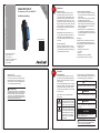 1
1
-
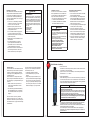 2
2
-
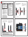 3
3
-
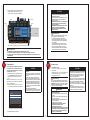 4
4
-
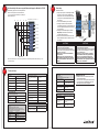 5
5
-
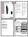 6
6
-
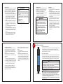 7
7
-
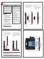 8
8
-
 9
9
-
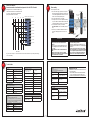 10
10


janitza 800-CT8-LP Installationsanleitung
- Kategorie
- Messung
- Typ
- Installationsanleitung
in anderen Sprachen
Verwandte Artikel
Andere Dokumente
-
Eurotherm 2204e,2208e Bedienungsanleitung
-
-
PILZ PNOZ mi2p Operating Instructions Manual
-
Panasonic KXMB2061 Bedienungsanleitung
-
-
-
-
Toro ProPass 200 Top Dresser Benutzerhandbuch