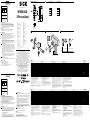
SICK WTB4SLC-3Pxxxx(Axx) Photoelectric proximity sensor Bedienungsanleitung
- Typ
- Bedienungsanleitung

ENGLISH
Photoelectric proximity sensor
with visible redlight (laser)
Operating Instructions
EN/IEC 60825-1:2014
IEC60825-1:2007
LASERKLASSE 1
Laser
1
Maximum pulse power < 2,5 mW
Puls length: 4 µs
Wavelength: 650 - 670 nm
Complies with 21 CFR 1040.10
and 1040.11 except for deviations
pursuant to Laser Notice No. 50,
dated June 24, 2007
Safety specications
> Read the operating instructions before starting operation.
> Connection, assembly and settings only by competent technicians.
> Protect the device against moisture and soiling when operating.
> No safety component in accordance with EU machine guidelines. For
use in NFPA 79 applications only. UL-listed adapters providing eld
wiring leads are available. Enclosure type 1.
Proper use
The WTB4SLC-3Pxxxx(Axx) photoelectric proximity sensor is an opto-elec-
tronic sensor for the optical, non-contact detection of objects.
Starting operation
1 Fit the sensor in a suitable bracket. Suitable mounting brackets can
be found in the SICK accessories range, for example.
Operation in standard I/O-Mode (SIO): The sensors must be con-
nected in a voltage-free state (VS = 0 V). The information in the graph-
ics [B] must be observed, depending on the type of connection:
‒ Male connector connection: pin assignment
‒ Cable: core color
Operation in IO-Link mode (IOL): Connect the device to a suitable
IO-Link master and integrate it into the control system via IODD /
Function Block. Device-specic IODD and Function Block are available
to download under the sensor order number at www.sick.com.
2 Setting sensing distance:
The sensing range is adjusted by pressing the teach-in pushbutton.
Do not operate the teach-in pushbutton using sharp objects. We rec-
ommend placing the switching state in the object, e. g., see graphic 2.
Once the sensing range has been adjusted, the object is removed from
the path of the beam, which causes the background to be suppressed
and the switching output to change (see graphic 3).
Please refer to the enclosed operating instructions for the IO-Link
photoelectric sensor for information about adjusting the IO-Link
sensing range.
The sensor is adjusted and ready for operation. Refer to graphics 2
and 3 to check the function. If the switching output fails to behave in
accordance with graphic 3, check application conditions .
3 PNP (Load → M)
C = communication (e.g. IO-Link)
MF = Multifunction input / output (e.g. Teach-in input or alarm output
Maintenance
SICK sensors are maintenance-free.
We recommend doing the following regularly
‒ clean the external lens surfaces.
‒ check the screw connections and plug-in connections.
No modications may be made to devices.
DEUTSCH
Reflexions-Lichttaster
mit sichtbarem Rotlicht (Laser)
Betriebsanleitung
EN/IEC 60825-1:2014
IEC60825-1:2007
LASERKLASSE 1
Laser
1
Maximale Pulsleistung: < 2,5 mW
Impulsdauer: 4 µs
Wellenlänge: 650 - 670 nm
Entspricht 21 CFR 1040.10
und 1040.11 mit Ausnahme von
Abweichungen nach
Laser-Hinweis 50, 24. Juni 2007
Sicherheitshinweise
> Vor der Inbetriebnahme die Betriebsanleitung lesen.
> Anschluss, Montage und Einstellung nur durch Fachpersonal.
> Gerät bei Inbetriebnahme vor Feuchte und Verunreinigung schützen.
> Kein Sicherheitsbauteil gemäß EU-Maschinenrichtlinie. Nur zur
Verwendung in Anwendungen gemäß NFPA 79. Von UL gelistete Adapter
mit Anschlusskabeln sind verfügbar. Enclosure type 1.
Bestimmungsgemäße Verwendung
Der Reflexions-Lichttaster WTB4SLC-3Pxxxx(Axx) ist ein optoelektronischer
Sensor und wird zum optischen, berührungslosen Erfassen von Objekten
eingesetzt.
Inbetriebnahme
1 Montieren Sie den Sensor in einem geeigneten Halter. Geeignete Be-
festigungswinkel nden Sie beispielsweise im SICK Zubehörangebot.
Betrieb im Standard I/O-Modus (SIO): Anschluss der Sensoren muss
spannungsfrei (U
V
= 0 V) erfolgen. Je nach Anschlussart sind die
Informationen in den Graken [vgl. B] zu beachten:
– Steckeranschluss: Pinbelegung
– Leitung: Adernfarbe
Betrieb im IO-Link-Modus: Gerät an geeigneten IO-Link-Master
anschließen und per IODD / Funktionsblock im Master, bzw. in der
Steuerung integrieren. IODD und Funktionsblock stehen unter www.
sick.com unter der Bestellnummer zum Download bereit.
More representatives and agencies at www.sick.com ∙ Subject to change
without notice ∙ The specied product features and technical data do not
represent any guarantee.
Weitere Niederlassungen nden Sie unter www.sick.com ∙ Irrtümer
und Änderungen vorbehalten ∙ Angegebene Produkteigenschaften und
technische Daten stellen keine Garantieerklärung dar.
Plus de représentations et d’agences à l’adresse www.sick.com ∙ Sujet à
modication sans préavis ∙ Les caractéristiques de produit et techniques
indiquées ne constituent pas de déclaration de garantie.
Para mais representantes e agências, consulte www.sick.com ∙ Alterações
poderão ser feitas sem prévio aviso ∙ As características do produto e os
dados técnicos apresentados não constituem declaração de garantia.
Altri rappresentanti ed agenzie si trovano su www.sick.com ∙ Contenuti
soggetti a modiche senza preavviso ∙ Le caratteristiche del prodotto e i dati
tecnici non rappresentano una dichiarazione di garanzia.
Más representantes y agencias en www.sick.com ∙ Sujeto a cambio sin
previo aviso ∙ Las características y los datos técnicos especicados no
constituyen ninguna declaración de garantía.
欲了解更多代表机构和代理商信息,请登录 www.sick.com ∙
如有更改 , 不另行通知 ∙ 对所给出的产品特性和技术参数
的正确性不予保证。
その他の営業所は www.sick.com よりご覧ください ∙ 予告なしに
変更されることがあります ∙ 記載されている製品機能およ
び技術データは保証を明示するものではありません。
WTB4SLC-
3Pxxxx(Axx)
------------------------------------------------------- 8020421.ZM24 1118 COMAT -----------------------------------------------------
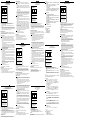
A WTB4SLC-3Pxxxx(Axx)
1
2 Einstellung Tastweite
Der Schaltabstand kann durch Drücken der Einlernen-Taste angepasst
werden.
Die Einlernen-Taste nicht mit scharfen Gegenständen betätigen. Wir
empfehlen, den Schaltzustand z. B. in dem Objekt einzustellen, siehe
Grak 2.
Nach der Anpassung des Schaltabstands ragt das Objekt nicht länger
in den Lichtstrahl, wodurch der Hintergrund ausgeblendet und das
Ausgangsschaltelement geändert wird (siehe Grak 3).
Weitere Informationen über die Einstellung des IO-Link Schaltab-
standes nden Sie in der beigelegten Betriebsanleitung der IO-Link
Lichtschranke.
Der Sensor ist nun ordnungsgemäß eingestellt und betriebsbereit.
Siehe Graken 2 und 3 zur Überprüfung der Funktion. Entspricht das
Verhalten des Ausgangsschaltelementes nicht der Grak 3, so sind die
Einsatzbedingungen zu überprüfen.
3 PNP (Last --> M)
C = Kommunikation (z. B. IO-Link)
MF = Multifunktion, programmierbarer Ausgang
Wartung
SICK-Sensoren sind wartungsfrei.
Wir empfehlen, in regelmäßigen Abständen
‒ die optischen Grenzflächen zu reinigen,
‒ Verschraubungen und Steckverbindungen zu überprüfen.
Veränderungen an Geräten dürfen nicht vorgenommen werden.
2
3
WTB4SLC -3Pxx6x(Axx)
Laser class Laserklasse Laser de classe Classe de laser 1
Sensing range Schaltabstand Distance de commutation Distância de comutação 25 … 300 mm
1)
Light spot diameter/distance Lichtfleckdurchmesser/Entfernung Diamètre de la tache lumineuse/Distance Diâmetro do ponto de luz/distância < 1.0 mm/170 mm
Supply voltage V
S
Versorgungsspannung U
V
Tension d’alimentation U
V
Tensão de força U
V
10 ... 30 V DC
2)
Output current I
max
Ausgangsstrom I
max
Courant de sortie I
max
Corrente de saída I
max
≤ 100 mA
Communication mode Kommunikationsmodus Mode de communication Modo de comunicação COM2
IO-Link IO-Link IO-Link IO-Link 1.1
Signal sequence min Signalfolge min Fréquence min Sequência min de sinais 1000/s
3)
Response time Ansprechzeit Temps de réponse Tempo de reação 300 ... 450 µs
3)
Enclosure rating Schutzart Type de protection Tipo de proteção IP 66, IP 67
Protection class Schutzklasse Classe de protection Classe de proteção
Circuit protection Schutzschaltungen Circuits de protection Circuitos protetores A, B, C
4)
Ambient operating temperature Betriebsumgebungstemperatur Température ambiante Temperatura ambiente de operação –10 … +50 °C
Extended ambient operating temperature Erweiterte Betriebsumgebungstemperatur Température ambiante de service étendue Temperatura ambiente operacional ampliada –30 ... +55 °C
5)
1)
Object 90 % reflection according to DIN 5033
2)
Limits, reverse polarity protected,
Operation in short-circuit protected network max 8 A
3)
Valid for Q\ on Pin2, if configured with software
4)
A = V
S
connections reverse polarity protected
B = inputs/outputs reverse polarity protected
C = interference pulse suppression
5)
As of T
U
= 50 °C a supply voltage of V
max
= 24 V and max. output
current
of I
max
= 50 mA is permissible.
Operation below T
U
= –10 °C is possible if the sensor is already
switched on at
T
U
> –10 °C, then cools down and the supply voltage is subse-
quently not switched off. Switching on below T
U
= –10 °C is not
permissible.
1)
Objekt 90 % Remission nach DIN 5033
2)
Grenzwerte, verpolsicher,
Betrieb in kurzschlussgeschütztem Netz max 8 A
3)
Gültig für Q\ auf Pin2, wenn per Software konfiguriert
4)
A = U
V
-Anschlüsse verpolsicher
B = Ein- und Ausgänge verpolsicher
C = Störimpulsunterdrückung“
5)
Ab T
U
= 50 °C ist eine Versorgungsspannung V
max
= 24 V
und ein max. Ausgangsstrom I
max
= 50 mA zulässig.
Ein Betrieb unter T
U
= –10 °C ist möglich, wenn der Sensor bereits
bei T
U
> –10 °C eingeschaltet wird, dann abkühlt und nicht mehr
von der Versorgungsspannung getrennt wird. Ein Einschalten unter
T
U
= –10 °C ist nicht zulässig.
1)
Objet Luminance de 90 % selon DIN 5033
2)
Valeurs limites, protégé contre l'inversion de polarité,
Service dans un réseau protégé contre les courts-circuits 8 A au
maximum
3)
Valable pour Q\ sur la broche 2 en cas de configuration logicielle
4)
A = Raccordements U
V
protégés contre les inversions de polarité
B = Entrées/Sorties protégées contre les inversions de polarité
C = Suppression des impulsions parasites
5)
A partir d’une température de 50 °C, une tension d’alimentation
de V
max
= 24 V
et un courant de sortie maxi. I
max
= 50 mA sont autorisés.
Un fonctionnement à une température inf. à –10 °C est possible
si le capteur avait déjà été allumé à une temp. > –10 °C, s’il s’est
ensuite refroidit et s’il n’a pas été entre temps débranché de la
tension d’alimentation. Une mise en marche à une température
inf. à –10 °C n’est pas autorisée.
1)
Objeto: 90 % de remissão segundo DIN 5033
2)
Valores limite, protegido contra polaridade reversa,
Operação em rede protegida contra curto-circuitos max 8 A
3)
Válido para Q\ no pino 2, quando configurado por software
4)
A = Conexões U
V
protegidas contra inversão de polos
B = Entradas/saídas protegidas contra inversão de polos
C = Supressão de impulsos parasitas
5)
A partir de uma temperatura ambiente de 50 °C é permitida uma
tensão de
alimentação V
max
= 24 V e uma corrente máxima de saída I
max
= 50 mA.
Um funcionamento abaixo da temperatura ambiente de –10 °C é
possível quando o sensor é ligado a uma temperatura ambiente
> –10 °C, em seguida é arrefecido e não mais desconectado da
tensão de alimentação. Não é permitido ligá-lo a uma temperatu-
ra abaixo de –10°C.
WTB4SLC -3Pxx6x(Axx)
Laser classe Clase de láser
级激光产品 クラスレーザ製品
Класс лазера 1
Distanza di commutazione Distancia de conmutación
开关间距
スイッチ間隔
Расстояние срабатывания, макс. 25 … 300 mm
1)
Diametro punto luminoso/distanza Diámetro/distancia de mancha de luz
光点直径 / 距离 スポット径 / 距離
Диаметр светового пятна/расстояние < 1.0 mm/170 mm
Tensione di alimentazione U
V
Tensión de alimentación U
V
电源电压 U
V
供給電圧 U
V
Напряжение питания U
V
10 ... 30 V DC
2)
Corrente di uscita I
max
Corriente de salida I
max
输出电流 I
max
最大出力電流 I
max
Выходной ток I
макс
. ≤ 100 mA
Modalità di comunicazione Modo de comunicación
通信模式 通信モード
Режим коммуникации COM2
IO-Link IO-Link IO-Link IO-Link IO-Link 1.1
Sequenza signali min Secuencia de señales min
信号流 min 信号伝達時間 min
Частота срабатывания макс. 1000/s
3)
Tempo di risposta Tiempo de reacción
触发时间 応答時間
Время отклика макс. 300 ... 450 µs
3)
Tipo di protezione Tipo de protección
保护种类 保護等級
Класс защиты IP 66, IP 67
Classe di protezione Protección clase
保护级别 保護クラス
Класс защиты
Commutazioni di protezione Circuitos de protección
保护电路 保護回路
Схемы защиты
4)
A, B, C
3)
Temperatura ambiente circostante Temperatura ambiente de servicio
工作环境-温度 動作周囲温度
Диапазон рабочих температур –10 … +50 °C
Temperatura di funzionamento ambientale estesa Temperatura ambiente de servicio ampliada
更大的运行环境温度范围 動作周囲温度の拡大
Диапазон рабочих температур, макс. –30 ... +55 °C
4)
1)
Oggetto 90 %, remissione sec. DIN 5033
2)
Valori limite, Con protezione dall’inversione di polarità.
Funzionamento in rete con protezione dai cortocircuiti max 8 A
3)
Valido per Q\ su Pin2, se configurato tramite software
4)
A = U
V
-collegamenti con protez. contro inversione di poli
B = entrate/uscite con protezione contro invesione di poli
C = soppressione impulsi di disturbo
5)
A partire da una temperatura di 50°C sono consentite una
tensione di
approvvigionamento V
max
= 24 V e una corrente in uscita massima
I
max
= 50 mA.
È possibile un funzionamento sotto i –10 °C, se il sensore viene
acceso a una
temperatura > –10 °C, quindi viene raffreddato e non viene più
staccato dalla tensione di approvvigionamento. Non è consentita
l’accensione sotto i –10 °C.
1)
Objeto 90 % de remission en base a DIN 5033
2)
Valores límite, Protección contra polarización inversa,
Funcionamiento en la red protegida contra cortocircuito, max 8 A
3)
Válido para Q\ en Pin2 si está configurado por software
4)
A = Conexiones U
V
a prueba de inversión de polaridad
B = Entradas/salidad a prueba de inversión de polaridad
C = Represión de impulso de interferencia
5)
A partir de T
U
= 50 °C se permite una tensión de alimentación V
max
= 24 V
y una corriente de salida I
max
= 50 mA.
Puede funcionar con T
U
= –10 °C si el sensor se conecta con T
U
> –10°C , a
continuación se enfría y no se vuelve a separar de la tensión de
alimentación.
No está permitida la conexión a valores inferiores de T
U
= –10°C
1)
90 % 漫反射比物体按照 DIN 5033
2)
极限值,反极性保护,
在防短路电路中运行,最大 8 A 。
3)
若通过软件完成配置,则适用于针脚 2 的 Q\
4)
A = U
V
-接头防反接
B = 输入 / 输出防反接
C = 消除干扰脉冲
5)
超过 50 °C 时允许的最大电源电压 V
max
为 24 V,
最大输出电流 I
max
为 50 mA 。
可在低于 –10 °C 时运行,前提是传感器已在高于 –10
°C 时开启,
然后降温且不断电。不得在低于 –10 °C 时开启。
1)
対象物 90 % の反射率 DIN 5033 に準拠
2)
限界値、逆極保護、
短絡保護された回路での使用最大 8 A 。
3)
ピン2のQ\ に有効、ソフトウェアを介して設定する場
合
4)
A = U
V
電源電圧逆接保護
B = 出力回路逆接保護
C = 干渉パルス抑制
5)
T
U
(周囲温度)= 50 °C 以上は、供給電圧 V
max
= 24 V
および最大出力電流 I
max
= 50 mA が許可されていま
す。
T
U
= -10 °C 以下での動作は、センサがすでに T
U
>
-10 °C でオンに
された後冷却され、供給電源から切断されていない
場合に可能となります。T
U
= -10 °C 以下でスイッチを
オンにすることは許可されて
いません。
1)
объект – ремиссия 90 % (относительно стандартного белого по
DIN 5033)
2)
Предельные значения:
эксплуатация в защищенной от короткого замыкания сети
макс. 8 А
3)
действительно для Q \ на PIN2, если сконфигурировано
программным обеспечением
4)
A = U
V
-подключения с защитой от перепутывания полюсов
B = входы и выходы с защитой от перепутывания полюсов
C = подавление импульсных помех
5)
Начиная от T
U
= 50 °C допустимо напряжение питания V
max
=
24 В и макс. выходной ток I
max
= 50 мА. Возможна эксплуатация
при температуре ниже
T
U
= -10 °C, если сенсор включается уже при T
U
> -10 °C, затем
охлаждается и уже не отсоединяется от сети подачи напряжения
питания. Включение при T
U
= -10 °C недопустимо.
+ (L+)
Q
L1
/C
MF
− (M)
brn
blk
wht
blu
1
+ (L+)
Q
L1
/C
MF
− (M)
4
2
3
brn
blk
wht
blu
B WTB4SL-3P1xxx WTB4SL-3P22xx
12.2
(0.48)
2.7
(0.11)
7.1
(0.28)
8.4
(0.33)
M8
17.3
(0.68)
29
(1.14)
12.8
(0.50)
2.8
(0.11)
12
(0.47)
50% 50%
Q
a)
a) WTB9xxL-3xxx6x: 25 ... 300 mm/90 %
WTB9xxL-3xxx9x: 25 ... 400 mm/90 %
50%
50%
Q (P
NP)
Q (NP
N)
BZ int48
Please find detailed addresses and further locations in all major industrial
nations at www.sick.com
Australia
Phone +61 (3) 9457 0600
Austria
Phone +43 (0) 2236 62288-0
Belgium/Luxembourg
Phone +32 (0) 2 466 55 66
Brazil
Phone +55 11 3215-4900
Canada
Phone +1 905.771.1444
Czech Republic
Phone +420 2 57 91 18 50
Chile
Phone +56 (2) 2274 7430
China
Phone +86 20 2882 3600
Denmark
Phone +45 45 82 64 00
Finland
Phone +358-9-25 15 800
France
Phone +33 1 64 62 35 00
Germany
Phone +49 (0) 2 11 53 01
Hong Kong
Phone +852 2153 6300
Hungary
Phone +36 1 371 2680
India
Phone +91-22-6119 8900
Israel
Phone +972-4-6881000
Italy
Phone +39 02 27 43 41
Japan
Phone +81 3 5309 2112
Malaysia
Phone +603-8080 7425
Mexico
Phone +52 (472) 748 9451
Netherlands
Phone +31 (0) 30 229 25 44
New Zealand
Phone +64 9 415 0459
Norway
Phone +47 67 81 50 00
Poland
Phone +48 22 539 41 00
Romania
Phone +40 356-17 11 20
Russia
Phone +7 495 283 09 90
Singapore
Phone +65 6744 3732
Slovakia
Phone +421 482 901 201
Slovenia
Phone +386 591 78849
South Africa
Phone +27 (0)11 472 3733
South Korea
Phone +82 2 786 6321
Spain
Phone +34 93 480 31 00
Sweden
Phone +46 10 110 10 00
Switzerland
Phone +41 41 619 29 39
Taiwan
Phone +886-2-2375-6288
Thailand
Phone +66 2 645 0009
Turkey
Phone +90 (216) 528 50 00
United Arab Emirates
Phone +971 (0) 4 88 65 878
United Kingdom
Phone +44 (0)17278 31121
USA
Phone +1 800.325.7425
Vietnam
Phone +65 6744 3732
SICK AG, Erwin-Sick-Strasse 1, D-79183 Waldkirch
Seite wird geladen ...
-
 1
1
-
 2
2


SICK WTB4SLC-3Pxxxx(Axx) Photoelectric proximity sensor Bedienungsanleitung
- Typ
- Bedienungsanleitung
in anderen Sprachen
- English: SICK WTB4SLC-3Pxxxx(Axx) Photoelectric proximity sensor Operating instructions
- français: SICK WTB4SLC-3Pxxxx(Axx) Photoelectric proximity sensor Mode d'emploi
- español: SICK WTB4SLC-3Pxxxx(Axx) Photoelectric proximity sensor Instrucciones de operación
- italiano: SICK WTB4SLC-3Pxxxx(Axx) Photoelectric proximity sensor Istruzioni per l'uso
- русский: SICK WTB4SLC-3Pxxxx(Axx) Photoelectric proximity sensor Инструкция по эксплуатации
- português: SICK WTB4SLC-3Pxxxx(Axx) Photoelectric proximity sensor Instruções de operação
- 日本語: SICK WTB4SLC-3Pxxxx(Axx) Photoelectric proximity sensor 取扱説明書
Verwandte Artikel
-
SICK WTB9LC-3Pxxxx(Axx) Photoelectric Proximity Sensor Bedienungsanleitung
-
-
-
-
-
-
-
-
-