
WT27K-2F430
---------------------------------------------------------------------------------------------------------------------------------------------------------------------------------------------------------------------------------------------------
A
!
B
$§
-------------------------------------------------------------------------------- 8015422.ZM31 1118 COMAT ----------------------------------------------------------------------------
ENGLISH
Photoelectric Proximity Sensor
with laser light
Operating Instructions
EN/IEC 60825-1:2014
IEC60825-1:2007
LASERKLASSE 1
Laser
1
Maximum pulse power < 2,0 mW
Puls length: 4,5 µs
Wavelength: 650 nm
Complies with 21 CFR 1040.10
and 1040.11 except for deviations
pursuant to Laser Notice No. 50,
dated June 24, 2007
a
CAUTION: Use of controls or adjustments or performance of
procedures other than those specied herein may result in
hazardous radiation exposure.
Safety Specifications
• Read the operating instructions before starting operation.
• Connection, assembly, and settings only by competent technicians.
• The light beam of the LED may not focused with additional optical
parts.
• Protect the device against moisture and soiling when operating.
• No safety component in accordance with EU machine guidelines.
Proper Use
The WT27K-2F430 photoelectric proximity sensor is an opto electronic
sensor and is used for optical, non-contact detection of objects and
animals.
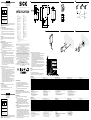
Starting Operation
!
The WT27K-2F430 has antivalent switching outputs:
WT27K-2F430 (PNP, load → M).
Q: dark-switching; object is not detected, output HIGH.
Q: light-switching; object is detected, output HIGH.
Select desired operating mode and connect as per connection
diagram B (Q, q).
"
Connect and secure cable receptacle tension-free.
The following apply for connection in B: brn = brown, blu = blue,
blk = black, wht = white.
§
Fix sensor to suitable holders (e.g. SICK mounting bracket).
Maintain direction in which object moves relative to sensor
(standard direction).
Connect photoelectric proximity sensor to operating voltage (see
type label).
Check application conditions such as sensing distance, size and
reectance of object to be detected as well as of background,
and compare with characteristic in diagram. (x = sensing
distance, y = transition range between set sensing distance and
reliable background suppression (z) in % of sensing distance,
Ro = reectance of object, Rh = reectance of background).
Reectance: 6 % = black, 18 % = gray, 90 % = white (based on
standard white to DIN 5033).
$
Alignment of sensor to the object:
Position object, position light spot on object, red sender light spot
visible on object.
Turn potentiometer to the right; the yellow signal strength indicator
must light continuously. Object is detected reliably.
If required, correct the sensing distance precisely for adaption to
the application conditions: Minimum turn of the potentiometer to
the right: sensing distance is increased. Minimum turn of potenti-
ometer to the left: sensing distance is decreased.
If the yellow signal strength indicator does not light, readjust the
photoelectric proximity switch, clean it and/or check the applica-
tion conditions and then repeat setting.
When the object is removed the signal strength indicator should
not light up. If it still lights up or ashes, the background is
detected. Reduce sensing distance with potentiometer until the
signal strength indicator does not light up any longer.
Maintenance
SICK photoelectric sensors are maintenance-free. We recommend
doing the following regularly:
– Clean the external lens surfaces.
– Check the screw connections and plug-in connections.
No modications may be made to devices.
DEUTSCH
Reexions-Lichttaster
mit Laserlicht
Betriebsanleitung
EN/IEC 60825-1:2014
IEC60825-1:2007
LASERKLASSE 1
Laser
1
Maximale Pulsleistung: < 2,0 mW
Impulsdauer: 4,5 µs
Wellenlänge: 650 nm
Entspricht 21 CFR 1040.10
und 1040.11 mit Ausnahme von
Abweichungen nach
Laser-Hinweis 50, 24. Juni 2007
a
ACHTUNG: Eingrie oder Manipulationen oder nicht bestim-
mungsgemäße Verwendung kann zu gefährlicher Belastung
durch Laser-Lichtstrahlung führen.
Sicherheitshinweise
• Vor der Inbetriebnahme die Betriebsanleitung lesen.
• Anschluss, Montage und Einstellung nur durch Fachpersonal.
• Die Strahlung des Sendelichtes darf nicht durch zusätzliche
optische Bauteile fokussiert werden.
• Gerät bei Inbetriebnahme vor Feuchte und Verunreinigung schüt-
zen.
• Kein Sicherheitsbauteil gemäß EU-Maschinenrichtlinie.
Bestimmungsgemäße Verwendung
Der Reexions-Lichttaster WT27K-2F430 ist ein opto elektronischer
Sensor und wird zum optischen, berührungslosen Erfassen von Sachen
und Tieren eingesetzt.
Inbetriebnahme
!
Der WT27K-2F430 hat antivalente Schaltausgänge:
WT27K-2F430 (PNP, Last → M):
Q: dunkelschaltend, Objekt wird nicht erkannt, Ausgang HIGH,
Q: hellschaltend, Objekt wird erkannt, Ausgang HIGH.
Gewünschte Betriebsart laut B anschliessen (Q, Q).
"
Leitungsdose spannungsfrei aufstecken und festschrauben.
Für Anschluss in B gilt: brn = braun, blu = blau, blk = schwarz,
wht = weiß.
§
Sensor an geeignete Halter anschrauben (z.B. SICK-Haltewinkel).
Bewegungsrichtung des Objektes relativ zum Taster einhalten
(Vorzugsrichtung).
Lichttaster an Betriebsspannung legen (s. Typenaufdruck).
Einsatzbedingungen wie Tastweite, Objektgröße und Remissions-
vermögen des Tastgutes sowie des Hintergrundes überprüfen
und mit der Kennlinie im Diagramm vergleichen. (x = Tastweite,
y = Übergangsbereich zwischen eingestellter Tastweite und siche-
rer Hintergrundausblendung (z) in % der Tastweite, Ro = Remission
Objekt, Rh = Remission Hintergrund).
Remission: 6 % = schwarz, 18 % = grau, 90 % = weiß (bezogen
auf Standardweiß nach DIN 5033).
WT27K-2F430
Sensing range
1)
, max. Tastweite
1)
, max. Distance de détection
1)
, max. Raio de exploração
1)
, max. 50 ... 800 mm
Operating range, adjustable
1)
Betriebstastweite, einstellbar
1)
Distance de détection, réglable
1)
Raio de exploração, ajusável
1)
100 … 800 mm
Light spot diameter/distance Lichtfleckdurchmesser/Entfernung Diamètre de la tache lumineuse/distance Diâmetro do ponto de luz/distância 2 mm/400 mm
Supply voltage V
S
2)
Versorgungsspannung U
V
2)
Tension d'alimentation U
V
2)
Tensão de força U
V
2)
10 ... 30 V DC
Output current I
max
Ausgangsstrom I
max.
Courant de sortie I
maxi
Corrente de saída I
máx.
100 mA
Switching frequency Schaltfrequenz
3)
Fréquence de commutation Frequência de ligação 50 Hz
Response time
4)
Ansprechzeit
4)
Temps de réponse
4)
Tempo de reação
4)
25 ms
Enclosure rating Schutzart Type de protection Tipo de proteção IP 65
Protection class
5)
Schutzklasse
5)
Classe de protection
5)
Classe de proteção
5)
Circuit protection
6)
Schutzschaltungen
6)
Circuits de protection
6)
Circuitos protetores
6)
A, B, C
Ambient operating temperature Betriebsumgebungstemperatur Température ambiante Temperatura ambiente de operação –10 … +45 °C
1)
Object 90 % reflection according to DIN 5033
2)
Limits
Residual ripple max. 5 V
PP
Operation in short-circuit protected network max. 8 A
3)
With light/dark ratio 1:1
4)
Signal transit time with resistive load
5)
Reference voltage 50 V DC
6)
A = V
S
connections reverse polarity protected
B = Outputs protected against short circuits
C = Interference pulse suppression
1)
Objekt 90 % Remission nach DIN 5033
2)
Grenzwerte
Restwelligkeit max. 5 V
SS
Betrieb im kurzschlussgeschützten Netz max. 8 A
3)
Bei Hell/Dunkelverhältnis 1:1
4)
Signallaufzeit bei ohmscher Last
5)
Bemessungsspannung DC 50 V
6)
A = U
V
-Anschlüsse verpolsicher
B = Ausgänge kurzschlussfest
C = Störimpulsunterdrückung
1)
Objet Luminance de 90 % selon DIN 5033
2)
Valeurs limites Ondulation résiduelle maxi 5 V
SS
Service dans un réseau protégé contre les courts-circuits 8 A au maximum
3)
Pour un rapport clair/sombre 1:1
4)
Durée du signal en charge ohmique
5)
Tension de calcul 50 V c.c.
6)
A = Raccordements U
V
protégés contre les inversions de polarité
B = Sorties protégées contre les courts-circuits
C = Suppression des impulsions parasites
1)
Objeto: 90% de remissão segundo DIN 5033
2)
Valores limite
Ondulação residual máx. 5 V
SS
Operação em rede protegida contra curto-circuitos máx. 8 A
3)
Com uma relação luminoso/escuro de 1:1
4)
Tempo de transição do sinal com carga ôhmica
5)
Tensão de dimensionamento DC 50 V
6)
A = Conexões U
V
protegidas contra inversão de polos
B = Saídas protegidas contra curto circuito
C = Supressão de impulsos parasitas
WT27K-2F430
Portata di ricezione
1)
, max. Alcance de palpación
1)
, max.
探测距离
1)
,max. 検出範囲
1)
、 最大
50 ... 800 mm
Distanza di ricezione, registrabile
1)
Margen de palpado en servicio, adjustable
1)
工作距离,可调节
1)
動作範囲、調節可能
1)
100 … 800 mm
Diametro punto luminoso/distanza Diámetro/distancia de mancha de luz
光点直径/距离 スポット径/距離
2 mm/400 mm
Tensione di alimentazione U
V
2)
Tensión de alimentación U
V
2)
电源电压U
V
2)
供給電圧 U
V
2)
10 ... 30 V DC
Corrente di uscita max. I
max.
Corriente de salida I
max.
输出电流I
max.
最大出力電流 I
max.
100 mA
Frequenza di commutazione Frecuencia de conmutación
开关频率 スイッチング周波数
50 Hz
Tempo di risposta
4)
Tiempo de reacción
4)
触发时间
4)
応答時間
4)
25 ms
Tipo di protezione Tipo de protección
保护种类(IEC60529) 保護等級
IP 65
Classe di protezione
5)
Protección clase
5)
保护级别
5)
保護クラス
5)
Commutazioni di protezione
6)
Circuitos de protección
6)
保护电路
6)
保護回路
6)
A, B, C
Temperatura ambiente circostante Temperatura ambiente de servicio
工作环境-温度 動作周囲温度
–10 … +45 °C
1)
Oggetto 90 % remissione sec. DIN 5033
2)
Valori limite
ondulazione residua max. 5 V
SS
Funzionamento in rete con protezione dai cortocircuiti max. 8 A
3)
Con relatio chiaro/scuro 1:1
4)
Tempo di continuare de segnale a resistenza ohmica
5)
Tensione di taratura DC 50 V
6)
A = U
V
-collegamenti con protezione contro inversione di poli
B = Uscite a prova di corto circuito
C = Soppressione impulsi
1)
Objeto 90 % de remission en base a DIN 5033
2)
Valores límite
ondulación residual max. 5 V
SS
Funcionamiento en la red protegida contra cortocircuito, máx. 8 A
3)
Con una relación claro/oscuro de 1:1
4)
Duración de la señal con carga óhmica
5)
Tensión tolerable DC 50 V
6)
A = Conexiones U
V
a prueba de inversión de polaridad
B = Salidas resistentes al cortocircuito
C = Represión de impulso de interferencia
1)
90 %漫反射比物体按照DIN5033
2)
极限值剩余波纹度max.5V
SS
操作电流:在防短路的网络里,
最大8A
3)
亮 / 暗比 1:1
4)
电阻性负载时,传感器检测到变化时输出信号的转换时间
5)
限定电压DC50V
6)
A = U
V
-接头防反接
B = 输出端抗过流-及短路
C = 消除干扰脉冲
1)
対象物 90 % 、反射率 DIN 5033 に準拠
2)
限界値:短絡保護された回路での使用
最大 8 A、リップル 最大 5 V
PP
3)
ライト/ダークの比率 1:1
4)
負荷のある信号経過時間
5)
基準電圧 50 V DC
6)
A = V
S
電源電圧逆接保護
B = 出力回路逆接保護
C = 干渉パルス抑制
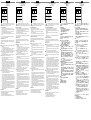
"
53.5
(2.11)
24.6
(0.97)
50.5
(1.99)
18
(0.71)
80
(3.15)
70
(2.76)
40
(1.57)
50
(1.97)
28.5
(1.12)
14.1
(0.56)
5
(0.20)
5
(0.20)
max.
16
(0.63)
5.2
(0.20)
43.5
(1.71)
61
(2.40)
20
(0.79)
25
(0.98)
28.5
(1.12)
14.1
(0.56)
12
(0.47)
4
(0.16)
5
(0.20)
4
(0.16)
5 (0.20)
More representatives and agencies at www.sick.com ∙ Subject to change
without notice ∙ The specied product features and technical data do not
represent any guarantee.
Weitere Niederlassungen nden Sie unter www.sick.com ∙ Irrtümer
und Änderungen vorbehalten ∙ Angegebene Produkteigenschaften und
technische Daten stellen keine Garantieerklärung dar.
Plus de représentations et d’agences à l’adresse www.sick.com ∙ Sujet à
modication sans préavis ∙ Les caractéristiques de produit et techniques
indiquées ne constituent pas de déclaration de garantie.
Para mais representantes e agências, consulte www.sick.com ∙ Alterações
poderão ser feitas sem prévio aviso ∙ As características do produto e os
dados técnicos apresentados não constituem declaração de garantia.
Altri rappresentanti ed agenzie si trovano su www.sick.com ∙ Contenuti
soggetti a modiche senza preavviso ∙ Le caratteristiche del prodotto e i dati
tecnici non rappresentano una dichiarazione di garanzia.
Más representantes y agencias en www.sick.com ∙ Sujeto a cambio sin
previo aviso ∙ Las características y los datos técnicos especicados no
constituyen ninguna declaración de garantía.
欲了解更多代表机构和代理商信息,请登录 www.sick.com ∙
如有更改, 不另行通知 ∙ 对所给出的产品特性和技术参数
的正确性不予保证。
その他の営業所はwww.sick.com よりご覧ください ・ 予告なしに変更され
ることがあります ・ 記載されている製品機能および技術データは保証を明
示するものではありません。
1
L+
Q
Q
M
4
2
3
brn
blk
blu
wht
BZ int48
Please find detailed addresses and further locations in all major industrial
nations at www.sick.com
Australia
Phone +61 (3) 9457 0600
Austria
Phone +43 (0) 2236 62288-0
Belgium/Luxembourg
Phone +32 (0) 2 466 55 66
Brazil
Phone +55 11 3215-4900
Canada
Phone +1 905.771.1444
Czech Republic
Phone +420 2 57 91 18 50
Chile
Phone +56 (2) 2274 7430
China
Phone +86 20 2882 3600
Denmark
Phone +45 45 82 64 00
Finland
Phone +358-9-25 15 800
France
Phone +33 1 64 62 35 00
Germany
Phone +49 (0) 2 11 53 01
Hong Kong
Phone +852 2153 6300
Hungary
Phone +36 1 371 2680
India
Phone +91-22-6119 8900
Israel
Phone +972-4-6881000
Italy
Phone +39 02 27 43 41
Japan
Phone +81 3 5309 2112
Malaysia
Phone +603-8080 7425
Mexico
Phone +52 (472) 748 9451
Netherlands
Phone +31 (0) 30 229 25 44
New Zealand
Phone +64 9 415 0459
Norway
Phone +47 67 81 50 00
Poland
Phone +48 22 539 41 00
Romania
Phone +40 356-17 11 20
Russia
Phone +7 495 283 09 90
Singapore
Phone +65 6744 3732
Slovakia
Phone +421 482 901 201
Slovenia
Phone +386 591 78849
South Africa
Phone +27 (0)11 472 3733
South Korea
Phone +82 2 786 6321
Spain
Phone +34 93 480 31 00
Sweden
Phone +46 10 110 10 00
Switzerland
Phone +41 41 619 29 39
Taiwan
Phone +886-2-2375-6288
Thailand
Phone +66 2 645 0009
Turkey
Phone +90 (216) 528 50 00
United Arab Emirates
Phone +971 (0) 4 88 65 878
United Kingdom
Phone +44 (0)17278 31121
USA
Phone +1 800.325.7425
Vietnam
Phone +65 6744 3732
SICK AG, Erwin-Sick-Strasse 1, D-79183 Waldkirch
$
Ausrichtung des Sensors auf das Objekt:
Objekt positionieren, Lichteck auf Objekt ausrichten, sichtbarer
roter Sendelichteck auf Objekt erkennbar.
Potentiometer nach rechts drehen, gelbe Empfangsanzeige muss
konstant leuchten: Objekt wird sicher erkannt.
Bei Bedarf Feinkorrektur des Tastabstandes zur Anpassung an
die Applikationsbedingungen: Minimale Rechtsdrehung des
Poti: Tastabstand wird erhöht. Minimale Linksdrehung des Poti:
Tastabstand wird verringert.
Leuchtet die gelbe Empfangsanzeige nicht oder blinkt sie, Licht-
taster neu justieren, reinigen bzw. Einsatzbedingungen prüfen und
Einstellung wiederholen.
Wenn Objekt entfernt wird, muss gelbe LED erlöschen. Erlischt sie
nicht oder blinkt sie, wird der Hintergrund erfasst. Tastweite am
Drehknopf so weit reduzieren, bis die gelbe LED erlischt.
Wartung
SICK-Lichttaster sind wartungsfrei. Wir empfehlen, in regelmäßigen
Abständen
– die optischen Grenzächen zu reinigen,
– Verschraubungen, Steckverbindungen und Justage zu überprüfen.
Veränderungen an Geräten dürfen nicht vorgenommen werden.
Seite wird geladen ...
-
 1
1
-
 2
2


SICK WT27K-2F430 Bedienungsanleitung
- Typ
- Bedienungsanleitung
- Dieses Handbuch eignet sich auch für
in anderen Sprachen
- English: SICK WT27K-2F430 Operating instructions
- français: SICK WT27K-2F430 Mode d'emploi
- español: SICK WT27K-2F430 Instrucciones de operación
- italiano: SICK WT27K-2F430 Istruzioni per l'uso
- português: SICK WT27K-2F430 Instruções de operação
- 日本語: SICK WT27K-2F430 取扱説明書
Verwandte Artikel
-
SICK BA WTB11-2 WTF11-2 Bedienungsanleitung
-
-
-
SICK WT23L-F430 Bedienungsanleitung
-
-
-
-
-
-
