Reely 1991061 Bedienungsanleitung
- Kategorie
- Ferngesteuertes Spielzeug
- Typ
- Bedienungsanleitung
Dieses Handbuch ist auch geeignet für

• Wenden Sie sich an eine Fachkraft, wenn Sie Zweifel über die Arbeitsweise, die Sicherheit
oder den Anschluss des Produkts haben.
• Lassen Sie Wartungs-, Anpassungs- und Reparaturarbeiten ausschließlich von einem
Fachmann bzw. einer Fachwerkstatt durchführen.
• Sollten Sie noch Fragen haben, die in dieser Bedienungsanleitung nicht beantwortet werden,
wenden Sie sich an uns oder einen anderen Fachmann.
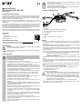
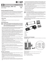
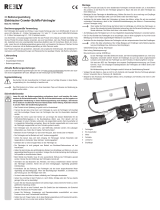
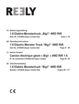
Anschlüsse und Bedienelemente
1 Fahrtregler
2 Anschlussstecker (mit Empfänger verbinden, auf Polarität achten)
3 Akkustecker (mit Fahrakku verbinden, auf Polarität achten)
4 Motoranschlusskabel
5 Ein-/Aus-Taste
6 Setup-Taste
7 Anschluss für Programmierkarte (auf Polarität achten)
8 LED
Montage
• Wenn das Produkt als Ersatz für einen bestehenden Fahrtregler verwendet werden soll, so kontrollieren
Sie zunächst, ob der Motor für den Fahrtregler geeignet ist. Bauen Sie dann den alten Fahrtregler aus
Ihrem Modell aus.
• Befestigen Sie den Fahrtregler im Modellfahrzeug. Wählen Sie einen Ort, der so weit weg vom Empfänger
ist wie möglich. Der Fahrtregler sollte auch nicht direkt neben dem Motor liegen.
• Verbinden Sie die beiden Kabel des Fahrtreglers mit denen des Motors, achten Sie auf eine eventuell
vorhandene Farbcodierung; damit ist die Vorwärts/Rückwärtsbewegung des Motors in Zusammenhang
mit dem Fahrtregler richtig.
Wenn später die Drehrichtung des Motors falsch ist (abhängig vom Antrieb des Fahrzeugs), so
können Sie entweder die beiden Motorkabel vertauschen oder die Reverse-Einstellung an Ihrem
Sender aktivieren. Der Motor dreht dann in die andere Richtung.
Kontrollieren Sie, ob die Zuordnung der Vorwärts-/Rückwärtsfahrt von Sender und Motor zu den
Fahrfunktionen des Fahrtreglers passt.
• Zur Befestigung des Fahrtreglers kann z.B. ein Stück Klettband bzw. doppelseitiges Klebeband verwendet
werden.
• Das kleine Gehäuse mit der Ein-/Aus-Taste und der Setup-Taste des Fahrtreglers ist so anzubringen, dass
die Bedienung leicht möglich ist. Auch hier ist die Befestigung mit einem Stück Klettband oder doppelsei-
tigem Klebeband vorzunehmen.
• Verbinden Sie den dreipoligen Stecker des Fahrtreglers mit dem entsprechenden Kanal des Empfängers.
Achten Sie dabei unbedingt auf die richtige Belegung am Empfänger (siehe Bedienungsanlei-
tung zum Empfänger bzw. Aufdruck auf dem Empfänger).
Die Farbcodierungen der Anschlusskabel von Fahrtregler und Servos sind üblicherweise wie folgt:
- Gelbe/weiße/orange Leitung: Steuersignal
- Rote Leitung: Betriebsspannung/+
- Braune/schwarze Leitung: GND/Minus/-
Da der Fahrtregler eine BEC-Elektronik besitzt, darf keine Empfängerbatterie bzw. kein Emp-
fängerakku verwendet werden! Sowohl der Empfänger als auch das daran angeschlossene
Lenkservo wird direkt über den Fahrtregler aus dem Fahrakku mit Spannung/Strom versorgt.
Soll statt dem BEC des Fahrtreglers eine separate Empfängerstromversorgung zum Einsatz
kommen, muss vom dreipoligen Empfängerstecker des Fahrtreglers der mittlere Draht (rote
Leitung, Betriebsspannung/+) unterbrochen werden.
Bei Nichtbeachtung wird der Fahrtregler zerstört! Verlust der Gewährleistung/Garantie!
• Verlegen Sie alle Kabel so, dass sie nicht in sich drehende oder bewegte Teile des Fahrzeugs gelangen
können. Verwenden Sie zur Fixierung z.B. Kabelbinder.
Bedienungsanleitung
Brushless-Fahrtregler „WP-1080“
Best.-Nr. 1991061
Bestimmungsgemäße Verwendung
Der Fahrtregler dient zur stufenlosen, elektronischen Drehzahlregelung eines Bürsten-Motors (geeigneter
Typ siehe Kapitel „Technische Daten“) und wird an einem freien Kanal eines Fernsteuerempfängers für
Modellfahrzeuge angeschlossen. Die Konguration des Fahrtreglers erfolgt über eine mitgelieferte Program-
mierkarte; sie ist aber auch über eine Setup-Taste möglich.
Abhängig vom angeschlossenen Motor kann der Fahrtregler mit einem LiPo-Fahrakku (2 - 3 Zellen, Nenn-
spannung 7,4 V oder 11,1 V) oder einem NiMH-/NiCd-Fahrakku (5 - 9 Zellen, Nennspannung 6,0 - 10,8 V)
betrieben werden.
Aus Sicherheits- und Zulassungsgründen dürfen Sie das Produkt nicht umbauen und/oder verändern. Falls
Sie das Produkt für andere Zwecke verwenden, als zuvor beschrieben, kann das Produkt beschädigt wer-
den. Außerdem kann eine unsachgemäße Verwendung Gefahren wie z.B. Kurzschluss, Brand, etc. hervor-
rufen. Lesen Sie sich die Bedienungsanleitung genau durch und bewahren Sie diese auf. Reichen Sie das
Produkt nur zusammen mit der Bedienungsanleitung an dritte Personen weiter.
Das Produkt entspricht den gesetzlichen, nationalen und europäischen Anforderungen. Alle enthaltenen Fir-
mennamen und Produktbezeichnungen sind Warenzeichen der jeweiligen Inhaber. Alle Rechte vorbehalten.
Lieferumfang
• Fahrtregler
• Programmierkarte
• Verbindungskabel für Programmierkarte
• Bedienungsanleitung
Aktuelle Bedienungsanleitungen
Laden Sie aktuelle Bedienungsanleitungen über den Link www.conrad.com/downloads herunter oder scan-
nen Sie den abgebildeten QR-Code. Befolgen Sie die Anweisungen auf der Webseite.
Symbol-Erklärung
Das Symbol mit dem Ausrufezeichen im Dreieck weist auf wichtige Hinweise in dieser Bedie-
nungsanleitung hin, die unbedingt zu beachten sind.
Das Pfeil-Symbol ist zu nden, wenn Ihnen besondere Tipps und Hinweise zur Bedienung ge-
geben werden sollen.
Sicherheitshinweise
Lesen Sie sich die Bedienungsanleitung aufmerksam durch und beachten Sie insbe-
sondere die Sicherheitshinweise. Falls Sie die Sicherheitshinweise und die Angaben zur
sachgemäßen Handhabung in dieser Bedienungsanleitung nicht befolgen, übernehmen
wir für dadurch resultierende Personen-/Sachschäden keine Haftung. Außerdem erlischt
in solchen Fällen die Gewährleistung/Garantie.
• Das Produkt ist kein Spielzeug, es gehört nicht in Kinderhände!
• Der Fahrtregler kann mit einem LiPo- oder einem NiMH-Akku betrieben werden. Die
zulässigen Zellenzahlen usw. nden Sie im Kapitel „Technische Daten“.
• Schalten Sie immer zuerst den Sender ein und bringen Sie dessen Bedienhebel für die
Fahrfunktion/Motorregelung in die Neutralstellung (Motor aus). Erst danach darf der
Fahrtregler mit einem Fahrakku verbunden und eingeschaltet werden. Beim Ausschalten ist
in umgekehrter Reihenfolge vorzugehen. Bevor der Sender ausgeschaltet wird, muss zuerst
der Fahrtregler ausgeschaltet und vom Fahrakku getrennt werden.
• Trennen Sie den Akku immer dann vom Fahrtregler, wenn der Fahrtregler nicht benötigt wird.
Bei kurzzeitigen Pausen kann der Fahrtregler über die Ein-/Aus-Taste deaktiviert werden.
• Betreiben Sie den Fahrtregler nur über einen Akkupack, aber niemals über ein Netzteil.
• Der Fahrtregler wird bei Betrieb sehr heiß. Verbrennungsgefahr!
• Achten Sie darauf, dass sich beim Umgang mit Fahrzeugen niemals Körperteile oder
Gegenstände in drehenden Teilen benden. Verletzungsgefahr!
• Schließen Sie nur einen einzigen Motor an den Fahrtregler an.
• Der Fahrtregler ist nicht geeignet zum Betrieb eines Brushless-Elektromotors mit drei
Anschlüssen.
• Halten Sie beim Einbau den größtmöglichen Abstand zum Empfänger und Motor ein, um eine
gegenseitige Beeinussung zu vermeiden. Verlegen Sie die Antennenleitung des Empfängers
nicht parallel zu stromführenden Kabeln.
• Beim Betrieb des Modells muss für eine ausreichende Kühlung des Fahrtreglers gesorgt
werden. Decken Sie den Kühlkörper des Fahrtreglers niemals ab!
• Vermeiden Sie das Blockieren des Antriebs. Die hieraus entstehenden Ströme könnten
den Fahrtregler zerstören. Achten Sie auf einen leichtgängigen, regelmäßig gewarteten
Antriebsstrang.
• Kontrollieren Sie das Fahrzeug, den Fahrtregler und den daran angeschlossenen Motor
regelmäßig auf Beschädigungen. Wenn Sie Beschädigungen feststellen, so betreiben Sie
das Fahrzeug bzw. den Fahrtregler nicht mehr.
• Vor dem Laden des Akkus ist dieser vollständig vom Fahrtregler abzustecken.
• Gehen Sie vorsichtig mit dem Produkt um, durch Stöße, Schläge oder dem Fall aus bereits
geringer Höhe wird es beschädigt.
• Lassen Sie das Verpackungsmaterial nicht achtlos liegen, dieses könnte für Kinder zu einem
gefährlichen Spielzeug werden.

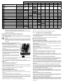
Die grau markierten Werte der Tabelle sind die Grundeinstellungen nach einem Reset. Mögli-
cherweise hat der Fahrtregler bei Lieferung eine andere Grundeinstellung; beachten Sie dann
die Blinksignale der LED bzw. die Anzeigen auf der Programmierkarte.
Der Motor gibt zusätzlich zum Blinksignal ein kurzes Tonsignal aus; dieses wird durch eine kurze
Ansteuerung des Motors erzeugt.
Programmierung der Sonderfunktionen des Fahrtreglers
Der Fahrtregler kann sowohl über die beiliegende Programmierkarte als auch über die Setup-Taste des
Fahrtreglers programmiert werden.
Abhängig vom Fahrzeug, in das Sie den Fahrtregler einbauen wollen, sind die Voreinstellungen
zu ändern.
Wenn Sie LiPo-Akkus zum Betrieb des Fahrzeugs verwenden, so kontrollieren Sie die Grund-
einstellung des Fahrtreglers, ob der Unterspannungsschutz aktiviert ist. Bei ausgeschalteter
Unterspannungserkennung kommt es andernfalls zu einer Tiefentladung der LiPo-Akkus, was
diese zerstört.
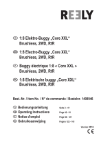
a) Programmierung über mitgelieferte Programmierkarte
• Verbinden Sie den Fahrtregler mit dem Fahrakku.
• Verbinden Sie die dreipolige Stiftleiste auf dem Fahrtregler
über das mitgelieferte Kabel mit der Programmierkarte.
Am Fahrtregler zeigt die schwarze Leitung des Kabels zum
Rand hin, an der Programmierkarte nach innen, siehe Abbil-
dungen rechts.
Der zweite dreipolige Anschluss auf der Programmierkarte
dient nur zur Stromversorgung, wenn diese nicht über den
Fahrtregler/Akku erfolgen sollte. Hier benötigen Sie eine se-
parate Batteriebox (nicht im Lieferumfang) mit einer Ausgangs-
spannung von 6 V/DC (4 Batterien); Polarität siehe Aufdruck
auf der Programmierkarte.
• Schalten Sie den Fahrtregler ein (Ein-/Aus-Taste kurz drücken).
• Die 7-Segmen-Anzeigen auf der Programmierkarte leuchten
nun auf.
Wenn auf der Programmierkarte keine Anzeigen erscheinen, so kontrollieren Sie die Verbindung
zwischen Fahrtregler und Programmierkarte.
• Mit der Taste „ITEM“ können Sie die gewünschte Programmierfunktion (1....15) auswählen.
Beachten Sie hierzu die Angaben in der Tabelle und im Kapitel „Beschreibung der Einstellfunk-
tionen“.
• Mit der Taste „VALUE“ lässt sich der Einstellwert wählen.
• Bestätigen Sie den Einstellwert mit der Taste „OK“.
• Falls Sie alle Programmierfunktionen auf die Grundeinstellungen zurücksetzen wollen (in der Tabelle grau
markiert), so drücken Sie die Taste „RESET“.
• Haben Sie alle Einstellungen vorgenommen, schalten Sie den Fahrtregler aus. Ziehen Sie dann den
Stecker des Verbindungskabels zur Programmierkarte aus dem Fahrtregler.
b) Programmierung über Setup-Taste
• Schalten Sie den Sender ein, falls noch nicht geschehen.
• Schalten Sie den Fahrtregler aus (Ein-/Aus-Taste länger als 0,5 Sekunden drücken).
• Halten Sie die Setup-Taste gedrückt und schalten Sie den Fahrtregler ein, indem Sie kurz die Ein-/Aus-
Taste drücken.
• Halten Sie die Setup-Taste weiter gedrückt, lassen Sie sie nicht los.
• Am Fahrtregler blinkt die rote LED 8x und der Motor gibt Pieptöne ab (Setup-Taste weiter gedrückt halten).
• Anschließend bendet sich der Fahrtregler im Programmiermodus. Die rote LED und Pieptöne vom Motor
zeigen an, welche Programmierfunktion gerade ausgewählt ist (siehe Tabelle und im Kapitel „Beschrei-
bung der Einstellfunktionen“). Halten Sie die Setup-Taste weiter gedrückt.
• Beispiel: Rote LED blinkt 2x kurz +2x kurzer Piepton: Akkutyp LiPo/NiMH auswählen
• Wenn die gewünschte Programmierfunktion angezeigt wird, die Sie verändern wollen (z.B. Akkutyp LiPo/
NiMH auswählen, rote LED blinkt 2x kurz + 2x kurze Pieptöne vom Motor), so lassen Sie die Setup-Taste
los.
• Die rote LED und die Pieptöne zeigen nun die jeweils verfügbaren Einstellwerte an.
Beispiel: Rote LED blinkt 1x kurz +1x kurzer Piepton: Akkutyp LiPo
Rote LED blinkt 2x kurz + 2x kurzer Piepton: Akkutyp NiMH
• Um die jeweilige Auswahl zu speichern, schalten Sie den Fahrtregler aus, indem Sie die Ein-/Aus-Taste
länger als 0,5 Sekunden drücken. Wenn Sie danach den Fahrtregler wieder einschalten, ist dieser mit den
neuen Einstellungen betriebsbereit.
• Soll eine weitere Einstellung verändert werden, gehen Sie wieder wie oben beschrieben vor.
Beschreibung der Einstellfunktionen
• Funktion #1, rote LED blinkt 1x kurz: Fahrmodus
Der Fahrtregler kann hier zwischen „Vorwärts/Bremse“, „Vorwärts/Bremse/Rückwärts“ und „Vorwärts/
Rückwärts“ umgeschaltet werden. Die Einstellung „Vorwärts/Rückwärts“ ist speziell für Crawler-Fahrzeu-
ge vorgesehen, da hier direkt zwischen Vorwärts- und Rückwärtsfahrt umgeschaltet werden kann (ohne
die störende Bremse).
• Funktion #2, rote LED blinkt 2x kurz: Akkutyp
Damit die Unterspannungsabschaltung korrekt arbeiten kann, muss hier der korrekte Akkutyp (LiPo oder
NiMH) ausgewählt werden.
• Funktion #3, rote LED blinkt 3x kurz: Unterspannungsschutz
Wird ein LiPo-Fahrakku verwendet, so ist unbedingt darauf zu achten, dass der Unterspannungsschutz
aktiviert wird.
Einstellung „Niedrig“: Spannungsgrenze NiMH = 4,5 V/Akkupack, LiPo = 3,0 V/Zelle
Einstellung „Mittel“: Spannungsgrenze NiMH = 5,0 V/Akkupack, LiPo = 3,2 V/Zelle
Einstellung „Hoch“: Spannungsgrenze NiMH = 5,5 V/Akkupack, LiPo = 3,4 V/Zelle
Fällt die Akkuspannung bei aktiviertem Unterspannungsschutz unter die angegebenen Werte, so verrin-
gert der Fahrtregler die Ausgangsleistung bzw. er schaltet den Motor ab. Dies verhindert eine schädliche
Tiefentladung.
• Funktion #4, rote LED blinkt 4x kurz: Start-Antriebsleistung bei Vorwärtsfahrt
Hier lässt sich einstellen, mit wieviel Antriebsleistung der Motor startet, wenn der Gas-/Bremshebel am
Sender die Neutralstellung verlässt. Je niedriger die Einstellung, umso sanfter kann angefahren werden.
• Funktion #5, rote LED blinkt 1x lang: Maximale Geschwindigkeit für Vorwärtsfahrt
Sie können in dieser Programmierfunktion die maximale Geschwindigkeit für die Vorwärtsfahrt einstellen.
Wenn Sie z.B. 50% einstellen, so fährt das Fahrzeug bei Vollgas am Sender nur etwa halb so schnell wie
bei 100%. Speziell bei einem Crawler-Fahrzeug ergibt sich somit ein sehr langsames und feinfühliges
Fahrverhalten.
• Funktion #6, rote LED blinkt 1x lang + 1x kurz: Maximale Geschwindigkeit für Rückwärtsfahrt
Sie können in dieser Programmierfunktion die maximale Geschwindigkeit für die Rückwärtsfahrt einstel-
len. In der Regel wird für „normale“ Fahrzeuge (Buggy, Monstertruck...) eine geringere Geschwindigkeit
als bei Vorwärtsfahrt eingestellt. Bei einem Crawler-Fahrzeug dagegen sollte für Vorwärts- und Rückwärts-
fahrt die gleiche Geschwindigkeit programmiert werden.
• Funktion #7, rote LED blinkt 1x lang + 2x kurz: Maximale Bremskraft
Durch höhere Einstellwerte lässt sich eine stärkere Verzögerung beim Bremsvorgang erzielen. Wird die
Bremse in Funktion #1 ausgeschaltet (z.B. für ein Crawler-Fahrzeug), so ist die hier vorgenommene Ein-
stellung irrelevant.
• Funktion #8, rote LED blinkt 1x lang + 3x kurz: Start-Bremskraft
Hier kann die Bremskraft eingestellt werden, mit der die Bremsfunktion einsetzt. Je niedriger die Ein-
stellung, umso sanfter setzt die Bremse ein. Wird die Bremse in Funktion #1 ausgeschaltet (z.B. für ein
Crawler-Fahrzeug), so ist die hier vorgenommene Einstellung irrelevant.
• Funktion #9, rote LED blinkt 1x lang + 4x kurz: Motorbremse
Wenn Sie das Gas am Sender wegnehmen bzw. den Gas-/Bremshebel am Sender in die Neutralstellung
zurückbewegen, wird das Fahrzeug von selbst verlangsamen. Die Wirkung ist damit genau wie bei der
Motorbrems-Funktion bei einem „echten“ Auto, wenn Sie das Gaspedal loslassen, ohne auf das Brems-
pedal zu treten.
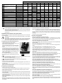
Verfügbare Einstellwerte der jeweiligen Programmierfunktion (Programmierkarte = Anzeige „VALUE“)
1 2 3 4 5 6 7 8 9
#
Programmierfunktion
(Programmierkarte = Anzeige „ITEM“)
LED blinkt (+Pieptöne) 1x kurz 2x kurz 3x kurz 4x kurz 1x lang
1x lang,
1x kurz
1x lang,
2x kurz
1x lang,
3x kurz
1x lang,
4x kurz
1 Fahrmodus 1x kurz
Vorwärts/
Bremse
Vorwärts/
Bremse/
Rückwärts
Vorwärts/
Rückwärts
2 Akkutyp 2x kurz LiPo NiMH
3 Unterspannungsschutrz 3x kurz Aus Niedrig Mittel Hoch
4 Start-Antriebsleistung bei Vorwärtsfahrt 4x kurz 0% 2% 4% 6% 8% 10% 12% 14% 16%
5 Max. Geschwindigkeit für Vorwärtsfahrt 1x lang 25% 50% 75% 100%
6 Max. Geschwindigkeit für Rückwärtsfahrt 1x lang, 1x kurz 25% 50% 75% 100%
7 Max. Bremskraft 1x lang, 2x kurz 0% 12,5% 25% 37,5% 50% 62,5% 75% 87,5% 100%
8 Start-Bremskraft 1x lang, 3x kurz 0% 6,25% 12,5% 18,75% 25% 31,25% 37,5% 43,75% 50%
9 Motorbremse 1x lang, 4x kurz 0% 5% 10% 50% 60% 70% 80% 90% 100%
10 Motorbrems-Rate 2x lang 1 (min.) 2 3 4 5 6 7 8 9 (max.)
11 Neutral-Bereich 2x lang, 1x kurz 0,02 ms 0,03 ms 0,04 ms 0,05 ms 0,06 ms 0,07 ms 0,08 ms 0,1 ms 0,12 ms
12 Startmodus 2x lang, 2x kurz 1 (min.) 2 3 4 5 6 7 8 9 (max.)
13 PWM-Frequenz 2x lang, 3x kurz 1 kHz 2 kHz 4 kHz 8 kHz 16 kHz
14 BEC-Spannung 2x lang, 4x kurz 6 V 7,4 V
15 Freilauf 3x lang Ein Aus

Dies ist eine Publikation der Conrad Electronic SE, Klaus-Conrad-Str. 1, D-92240 Hirschau (www.conrad.com).
Alle Rechte einschließlich Übersetzung vorbehalten. Reproduktionen jeder Art, z. B. Fotokopie, Mikroverlmung, oder die Erfassung in elektroni-
schen Datenverarbeitungsanlagen, bedürfen der schriftlichen Genehmigung des Herausgebers. Nachdruck, auch auszugsweise, verboten. Die
Publikation entspricht dem technischen Stand bei Drucklegung.
© Copyright 2019 by Conrad Electronic SE. 1991061_V1_0919_02_VTP_m_de
• Funktion #10, rote LED blinkt 2x lang: Motorbrems-Rate
Hier lässt sich einstellen, wie schnell die Motorbremse (Funktion #9) einsetzt. Je niedriger die Einstellung,
umso sanfter setzt die Motorbremse ein.
• Funktion #11, rote LED blinkt 2x lang + 1x kurz: Neutral-Bereich
In dieser Programmierfunktion kann eingestellt werden, wie groß der Bereich ist, den der elektronische
Fahrtregler als Neutralstellung des Senders erkennen soll. Je höher der Einstellwert (ms = Millisekunden),
umso größer der Neutral-Bereich.
• Funktion #12, rote LED blinkt 2x lang + 2x kurz: Startmodus
Abhängig von der Einstellung erfolgt das Losfahren mit weniger oder mehr Kraft. Bei einem Crawler sollte
ein niedriger Einstellwert gewählt werden, damit das Fahrzeug sanft anfahren kann.
• Funktion #13, rote LED blinkt 2x lang + 3x kurz: PWM-Frequenz (Taktfrequenz)
Durch eine höhere Einstellung ist eine feinfühligere Steuerung des Fahrtreglers möglich; durch die höhere
PWM-Frequenz erwärmt sich der Fahrtregler jedoch stärker.
• Funktion #14, rote LED blinkt 2x lang + 4x kurz: BEC-Spannung
Hier kann die BEC-Spannung (die Ausgangsspannung des Fahrtreglers für die Spannungsversorgung von
Empfänger und Lenkservo) eingestellt werden.
Aus Sicherheitsgründen ist immer die Einstellung 6 V zu verwenden, wenn Sie unsicher sind,
ob der Empfänger und das Lenkservo die höhere Einstellung zulassen. Bei Einstellung einer zu
hohen Spannung können Empfänger bzw. das Lenkservo beschädigt werden kann, Verlust von
Gewährleistung/Garantie!
• Funktion #15, rote LED blinkt 3x lang: Freilauf
Für Crawler-Fahrzeuge sollte diese Funktion eingeschaltet werden; damit ergibt sich ein lineares Fahrver-
halten bei niedrigen Geschwindigkeiten.
Programmierung von Neutral- und Vollgasstellung
Wenn das Fahrzeug in der Neutralstellung des Gas-/Bremshebels nicht ruhig stehen bleibt, können Sie am
Sender die Trimmung für die Fahrfunktion korrigieren. Sollte der Trimmweg nicht ausreichen (oder wenn
die Trimmung bereits fast am Ende des Trimmwegs steht), so können Sie die Neutralstellung und die Voll-
gasstellungen für Vorwärts-/Rückwärtsfahrt neu programmieren.
Gehen Sie dazu wie folgt vor:
• Schalten Sie den Sender ein, lassen Sie den Gas-/Bremshebel in Neutralstellung. Stellen Sie die Trim-
mung für die Fahrfunktion in die Mittelstellung.
• Schalten Sie den Fahrtregler aus (Ein-/Aus-Taste länger als 0,5 Sekunden drücken).
• Halten Sie die Setup-Taste gedrückt und schalten Sie den Fahrtregler ein, indem sie kurz die Ein-/Aus-
Taste drücken.
• Daraufhin blinkt die rote LED am Fahrtregler und der Motor gibt Pieptöne ab. Lassen Sie die Setup-Taste
wieder los.
Die Pieptöne werden durch eine kurze Ansteuerung des Motors erzeugt.
• Lassen Sie den Gas-/Bremshebel an Ihrem Sender los, so dass er in der Neutralstellung steht.
• Drücken Sie kurz die Setup-Taste, die rote LED am Fahrtregler blinkt 1x kurz, außerdem ist ein Piepton
hörbar. Die Neutralstellung ist gespeichert.
• Bewegen Sie den Gas-/Bremshebel am Sender in die Vollgasstellung für die Vorwärtsfahrt, ziehen Sie ihn
bis zum Anschlag in Richtung Griffstück und halten Sie ihn dort fest.
Achtung!
Wenn Sie den Gas-/Bremshebel des Senders während der Programmierung nicht oder nicht
weit genug bewegen, kann es nach Abschluss der Programmierung dazu kommen, dass das
Fahrzeug bereits auf winzige Bewegungen am Gas-/Bremshebel des Senders reagiert oder
auch unkontrollierbar wird. Nehmen Sie dann eine erneute Programmierung vor.
• Drücken Sie kurz die Setup-Taste, die rote LED am Fahrtregler blinkt 2x kurz und zwei Pieptöne sind
hörbar. Die Vollgasstellung für die Vorwärtsfahrt ist gespeichert.
• Bewegen Sie den Gas-/Bremshebel in die Vollgasstellung für die Rückwärtsfahrt, schieben Sie ihn bis
zum Anschlag vom Griff weg.
• Drücken Sie kurz die Setup-Taste, die rote LED am Fahrtregler blinkt 3x kurz und drei Pieptöne sind
hörbar. Die Vollgasstellung für die Rückwärtsfahrt ist gespeichert.
• Lassen Sie den Gas-/Bremshebel los, so dass er wieder in der Neutralstellung steht. Warten Sie jetzt
mindestens 3 Sekunden, dann wird der Einstellmodus verlassen und der Fahrtregler ist mit den vorgenom-
menen neuen Einstellungen betriebsbereit.
Reset des Fahrtreglers
Der Reset kann entweder über de Programmierkarte oder die Bedientasten des Fahrtreglers vorgenommen
werden.
Für den Reset über die Programmierkarte beachten Sie den Abschnitt „Programmierung über mitgelieferte
Programmierkarte“.
Soll der Reset über die Bedientasten des Fahrtreglers vorgenommen werden, so gehen Sie wie folgt vor:
• Schalten Sie den Sender ein. Lassen Sie den Gas-/Bremshebel in der Neutralstellung, bewegen Sie ihn
nicht.
• Schalten Sie den Fahrtregler ein (Ein-/Aus-Taste kurz drücken). Warten Sie, bis der Fahrtregler seinen
Selbsttest abgeschlossen hat und die LED nicht mehr blinkt/leuchtet.
Der Fahrtregler darf sich nicht im Programmiermodus benden.
• Halten Sie jetzt die Setup-Taste länger als 3 Sekunden gedrückt.
• Die rote LED auf dem Fahrtregler leuchtet 1x lang und es ist ein langes Tonsignal hörbar (das Tonsignal
wird über die Ansteuerung des Motors erzeugt). Anschließend blinkt die rote LED.
• Schalten Sie jetzt den Fahrtregler aus (Ein-/Aus-Taste länger als 0,5 Sekunden drücken).
• Wenn der Fahrtregler jetzt eingeschaltet wird, so sind alle Einstellungen auf die Grundeinstellungen zu-
rückgesetzt. Sie müssen nun wieder die Neutral- und Vollgasstellungen programmieren sowie alle ande-
ren Einstellungen vornehmen.
Inbetriebnahme des Fahrtreglers
Achtung, Vorsicht!
Platzieren Sie das Modellfahrzeug so, dass die Antriebsräder keinen Kontakt zum Boden oder
Gegenständen haben. Fassen Sie nicht in den Antrieb hinein, blockieren Sie ihn nicht! Verlet-
zungsgefahr!
• Schalten Sie den Sender ein und kontrollieren Sie anschließend den Akku- bzw. Batteriezustand des
Senders. Lassen Sie die Bedienelemente des Senders los, bewegen Sie sie nicht.
• Setzen Sie einen Fahrakku in Ihr Fahrzeug ein und verbinden Sie ihn mit dem Fahrtregler.
Achtung!
Achten Sie dabei auf die richtige Polung der Anschlusskabel des Fahrtreglers: Rot = Plus (+)
und Schwarz = Minus (-). Bei falschem Anschluss können der Fahrtregler und der Fahrakku
zerstört werden! Explosions-/Verbrennungsgefahr!
• Zum Einschalten des Fahrtreglers drücken Sie kurz den Ein-/Aus-Taster.
• Eine rote LED auf dem Fahrtregler dient zur Funktionsanzeige. Zur weiteren Signalisierung dienen außer-
dem Tonsignale, die durch eine kurze Ansteuerung des Antriebsmotors erzeugt werden.
Bedeutung der Ton-/LED-Signale Funktion
1x kurzer Ton, LED blinkt 1x kurz NiMH-Fahrakku erkannt
2x kurzer Ton, LED blinkt 2x kurz 2zelliger LiPo-Fahrakku erkannt
1x langer Ton, LED leuchtet 1x lang, LED
erlischt
Fahrtregler hat gültiges Signal vom Sender empfangen,
Gas-/Bremshebel ist in der Neutralstellung, Fahrtregler
ist betriebsbereit
LED blinkt dauernd Sender ist ausgeschaltet oder der Gas-/Bremshebel ist
nicht in der Neutralstellung
• Überprüfen Sie jetzt die Antriebs- und Lenkfunktionen des Fahrzeugs; beachten Sie hierzu die Bedie-
nungsanleitung zu Ihrer Fernsteueranlage.
Betrieb beenden
• Bringen Sie den Gas-/Bremshebel am Sender in die Neutralstellung, so dass das Fahrzeug still steht (ggf.
Trimmregler am Sender entsprechend korrigieren, damit der Motor stillsteht).
• Schalten Sie den Fahrtregler aus.
• Trennen Sie den Fahrakku vollständig vom Fahrtregler.
• Schalten Sie erst jetzt den Sender aus.
Übertemperaturschutz
Wird der Fahrtregler zu heiß, so wird der Motor wird ausgeschaltet. In diesem Fall gibt die rote LED Blinksi-
gnale ab. Kühlt sich der Fahrtregler ausreichend ab, so ist er wieder betriebsbereit.
Fail-Safe-Funktion
Der Fahrtregler schaltet den Motor aus Sicherheitsgründen ab, wenn kein gültiges Signal vom Empfänger
kommt. Die rote LED wird in diesem Fall blinken. Falls Ihr Sender/Empfänger eine eigene Fail-Safe-Funktion
bietet, so programmieren Sie diese korrekt! Prüfen Sie diese Funktion, damit diese im Fehlerfall korrekt
arbeitet.
Entsorgung
Elektronische Geräte sind Wertstoffe und gehören nicht in den Hausmüll. Entsorgen Sie das
Produkt am Ende seiner Lebensdauer gemäß den geltenden gesetzlichen Bestimmungen.
Technische Daten
Zellenzahl NiMH 5 - 9
Zellenzahl LiPo 2 - 3
Dauerstrom 80 A
Max. Strom (<1 Sek.) 400 A
BEC 6 V/DC oder 7,4 V (umschaltbar), max. 3 A
Unterspannungsabschaltung ja (abschaltbar)
Übertemperaturabschaltung ja
Failsafe-Funktion ja
Motorlimit bei 2 Zellen LiPo
oder 6 Zellen NiMH
Motortyp 540/550, ≥10 Turns (oder <30000 U/min bei 7,4 V)
Motorlimit bei 3 Zellen LiPo
oder 7 - 9 Zellen NiMH
Motortyp 540/550, ≥16 Turns (oder <20000 U/min bei 7,4 V)
Steckersystem für Empfänger JR
Programmieranschluss ja (Programmierkarte/Kabel im Lieferumfang)
Abmessungen (L x B x H) ca. 36,2 x 31,6 x 17 mm
Gewicht mit Kabel ca. 58,5 g

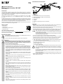
Connections and control elements
1 Speed controller
2 Connector plug (connect to receiver, ensure correct polarity)
3 Battery plug (connect to drive battery, ensure correct polarity)
4 Motor connection cable
5 On/off button
6 Setup key
7 Connection for programming card (ensure correct polarity)
8 LED
Installation
• If the product is to be used as a substitute for the existing speed controller, rst check that the motor is
suitable for the speed controller. Then remove the old speed controller from your model.
• Attach the speed controller to the model vehicle. Choose a location which is as far as possible from the
receiver. The speed controller should also not be directly next to the motor.
• Connect both cables of the speed controller to those of the motor, observing any existing colour coding
to ensure that the forward/reverse movement of the motor is correct in relation to the speed controller.
If later on the direction of rotation of the motor is wrong (depending on the vehicle drive), you
can either swap the two motor cables or use your transmitter to activate the reverse setting. The
motor then rotates in the other direction.
Check whether the assignment of the forward/reverse drive of the transmitter and motor match-
es the drive functions of the speed controller.
• You can use a hook-and-loop tape or a double-sided tape to x the speed controller.
• The small housing with the on/off button and the setup button of the speed controller is to be mounted
so that the easy operation is possible. Also use hook-and-loop tape or double-sided tape for installation.
• Connect the three-pole plug of the speed controller to the corresponding channel of the receiver.
Make absolutely sure you have the correct receiver conguration (see operating instructions for
receiver as well as the inscription on the receiver).
The connection cables of the speed controller and servos typically have the following colour codings:
- Yellow/white/orange cable: Control signal
- Red cable: Operating voltage/+
- Brown/black cable: GND/negative/-
Since the speed controller features a BEC electronics, there must not be used any receiver bat-
tery or receiver rechargeable battery! Both the receiver and the steering servo connected to it
will be powered with voltage/current directly through the speed controller, from the rechargeable
drive battery.
If a separate receiver power supply is to be used instead of the BEC of the speed controller, the
middle wire (red wire, operating voltage/+) must be disconnected from the three-pin receiver
plug of the speed controller.
Failure to comply with this instruction will permanently damage the speed controller! This will
void the warranty/guarantee.
• Position all cables so that they cannot become entangled in rotating or moving parts of the vehicle. Use
cable ties to afx them, for example.
Operating instructions
Brushless speed controller “WP-1080”
Item no. 1991061
Intended Use
The speed controller is intended for innitely variable, electronic rotational speed control of a brush motor
(see chapter "Technical Data" for suitable types) and is connected to a free channel of a remote control
receiver for model vehicles. The speed controller is congured using a supplied programming card; it can
also be congured by means of a setup button.
Depending on the connected motor, the speed controller can be equipped with a LiPo drive battery
(2 – 3 cells, nominal voltage 7.4 V or 11.1 V) or a NiMH/NiCd drive battery (5 – 9 cells, nominal voltage
6.0 – 10.8 V).
For safety and approval purposes, do not rebuild and/or modify this product. Using the product for purposes
other than those described above may damage the product. In addition, improper use can cause hazards
such as a short circuit or re. Read the operating instructions carefully and store them in a safe place. If you
pass the product on to a third party, please hand over these operating instructions as well.
This product complies with statutory, national and European regulations. All company and product names are
trademarks of their respective owners. All rights reserved.
Delivery content
• Speed controller
• Programming card
• Connecting cable for programming card
• Operating instructions
Up-to-date operating instructions
Download the up-to-date operating instructions at www.conrad.com/downloads or scan the QR code shown.
Follow the instructions on the website.
Explanation of symbols
The symbol with an exclamation mark in a triangle is used to highlight important information in
these operating instructions that must be observed.
The arrow symbol indicates special information and tips on how to use the product.
Safety instructions
Read the operating instructions and safety information carefully. If you do not follow the
safety information and information on proper handling in these operating instructions,
we will assume no liability for any resulting personal injury or damage to property. Such
cases will invalidate the warranty/guarantee.
• The product is not a toy and should be kept out of the reach of children!
• The speed controller can be operated with a LiPo or NiMH rechargeable battery. The
permissible number of cells and other specications can be found in chapter “Technical data”.
• Always switch on the transmitter rst and move its control lever for the drive function / motor
controller to the neutral position (motor off). Only after that, connect the speed controller to
the drive battery and switch it on. When switching off, proceed in the reverse order. Before
switching off the transmitter, turn off the speed controller and, if necessary, separate it from
the drive battery.
• Always disconnect the rechargeable battery from the speed controller when the speed
controller is not needed. For brief pauses, you can use the on/off button to deactivate the
speed controller.
• Operate the speed controller only with a rechargeable battery pack and never with a power
adaptor.
• The speed controller becomes very hot during operation. Risk of burn!
• When handling vehicles, ensure that no objects or body parts are in the rotating parts. Risk
of injury!
• Connect only a single motor to the speed controller.
• The speed controller is not suitable for operating a brushless electric motor with three
connections.
• Keep the greatest possible distance from the receiver and the motor during installation in
order to avoid mutual interference. Do not install the antenna cable of the receiver parallel
to live cables.
• When the model is operated, the speed controller must be cooled sufciently. Never cover the
heat sink of the speed controller!
• Avoid blocking the drive. The currents arising from this could destroy the speed controller.
Ensure a smooth-running, regularly serviced driveline.
• Check the vehicle, the speed controller and the motor connected to it for damage on a regular
basis. If you notice any damage, do not operate the vehicle or the speed controller any longer.
• Before charging the rechargeable battery, be sure to disconnect it completely from the speed
controller.
• Handle the product with care, it will be damaged by jolts, impacts or a fall from a low height.
• Do not leave packaging material carelessly lying around, as it could become a dangerous
toy for children.
• Consult a technician if you are not sure how to use or connect the product, or if you have
concerns about safety.
• Maintenance, modications and repairs must only be carried out by a technician or a specialist
repair centre.
• If you have any questions that are not answered in these operating instructions, please
contact us or another professional.

The values highlighted in grey in the table are the default settings after a reset. The speed con-
troller may have a different default setting upon delivery; in this case, observe the LED ashing
signals or the indicators on the programming card.
In addition to the ashing signal, the motor emits a short beep that is generated by a brief activa-
tion of the motor.
Programming special functions of the speed controller
The speed controller can be programmed using either the supplied programming card or the setup button
on the speed controller.
Depending on the vehicle in which you want to install the speed controller, you must change the
default settings.
When using LiPo rechargeable batteries to operate the vehicle, check the default setting of the
speed controller to see if the undervoltage protection is enabled. When low voltage detection is
disabled, LiPo rechargeable batteries are subject to a deep discharge that destroys them.
a Programming via the supplied programming card
• Connect the drive battery to the speed controller.
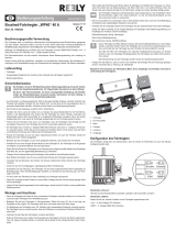
• Connect the three-pin header on the speed controller to the
programming card using the supplied cable.
On the speed controller, the black wire of the cable points to
the edge, on the programming card inwards, see gures on
the right.
The second three-pin connector on the programming card is
only used for power supply in cases where power is not sup-
plied via the speed controller/rechargeable battery. In this case,
you need a separate battery box (not included) with an output
voltage of 6 V/DC (4 batteries); polarity is indicated by an im-
print on the programming card.
• Turn on the speed controller (briey press the on/off button).
• The 7-segment indicators on the programming card will now
light up.
If no indicators light up on the programming card, check the connection between the speed
controller and the programming card.
• Use the “ITEM” button to select the desired programming function (1....15).
Observe the information in the table and in chapter “Overview of setup functions”.
• Use the “VALUE” button to select the setting.
• Press the “OK” button to conrm the setting.
• If you want to reset all programming functions to the default settings (highlighted in grey in the table), press
the “RESET” button.
• After you have made all settings, switch off the speed controller. Then unplug the connecting cable for the
programming card from the speed controller.
b Programming via the Setup Button
• Switch on the remote control, if not already done.
• Turn off the speed controller by pressing and holding down the on/off button for more than 0.5 seconds.
• Keep the setup button pressed and turn on the speed controller by briey pressing the on/off button.
• Keep holding down the setup button.
• The red LED on the speed controller will ash eight times and the motor will emit beeps (keep pressing
down the setup button).
• The speed controller is then in programming mode. The red LED and beeps emitted by the motor indicate
which programming function is currently selected (see table and chapter “Overview of setup functions”).
Keep the setup button pressed.
• Example: Red LED ashes twice briey and two short beeps are emitted: Select rechargeable battery
type LiPo/NiMH
• When the desired programming function you want to change is displayed (for example, select recharge-
able battery type LiPo/NiMH, red LED ashes twice briey and the motor emits two short beeps), release
the setup button.
• The red LED and the beeps now indicate the available settings.
Example: Red LED ashes once briey and one short beep is emitted: LiPo rechargeable battery type
Red LED ashes twice briey and two short beeps are emitted: NiMH rechargeable battery type
• To save the selection, turn off the speed controller by pressing and holding down the on/off button for
more than 0.5 seconds. If you then turn on the speed controller, it will be ready for operation with the
new settings.
• Follow the above steps to change the other settings.
Overview of setup functions
• Function #1, red LED ashes once briey: Driving mode
The speed controller can be switched between “forward/brake”, “forward/brake/reverse” and “forward/
reverse”. The “forward/reverse” setting is specially designed for crawler vehicles, because here you can
switch directly between forward and reverse (without applying the disturbing brake).
• Function #2, red LED ashes twice briey: Battery type
In order for the undervoltage cut-off to work properly, you must select the correct rechargeable battery
type (LiPo or NiMH).
• Function #3, red LED ashes thrice briey: Low voltage protection
If a LiPo drive rechargeable battery is used, it is essential to ensure that the low voltage protection is
enabled.
“Low” setting: NiMH voltage limit = 4.5 V/rechargeable battery pack, LiPo = 3.0 V/cell
“Medium” setting: NiMH voltage limit = 5.0 V/rechargeable battery pack, LiPo = 3.2 V/cell
“High” setting: NiMH voltage limit = 5.5 V/rechargeable battery pack, LiPo = 3.4 V/cell
If the rechargeable battery voltage falls below the specied values when the low voltage protection is
enabled, the speed controller will reduce the output power or turn off the motor. This prevents a detrimental
deep discharge.
• Function #4, red LED ashes four times briey: Start drive power when driving forward
Here you can set the amount of drive power the motor will start with when the throttle/brake lever on the
transmitter leaves the neutral position. The lower the setting, the smoother it can be started up.
• Function #5, red LED ashes once long: Maximum speed for forward drive
You can use this programming function to set the maximum speed for forward drive. For example, if you
set it at 50%, at full throttle on the transmitter the vehicle will run only about half as fast as at 100%. Espe-
cially with a crawler vehicle, this results in a very slow and sensitive driving behaviour.
• Function #6, red LED ashes once long and once briey: Maximum speed for reverse drive
You can use this programming function to set the maximum speed for reverse drive. As a rule, a speed
lower than that for forward drive is set for “normal” vehicles (buggy, monster truck...). In case of a crawler
vehicle, the same speed should be programmed for forward and reverse drive.
• Function #7, red LED ashes once long and twice briey: Maximum brake force
Higher settings can be used to achieve a greater braking delay. If the brake is disabled in function #1 (for
example, for a crawler vehicle), the setting made here is irrelevant.
• Function #8, red LED ashes once long and thrice briey: Start brake force
Here you can set the brake force for the brake function. The lower the setting, the smoother the brake is
applied. If the brake is disabled in function #1 (for example, for a crawler vehicle), the setting made here
is irrelevant.
• Function #9, red LED ashes once long and four times briey: Brake
If you release the throttle on the transmitter or move the throttle/brake lever on the transmitter back to the
neutral position, the vehicle will slow down by itself. The effect is just like the engine braking function on a
“real” car when you release the accelerator pedal without pressing the brake pedal.
• Function #10, red LED ashes twice long: Motor brake rate
Here you can set how fast the motor brake (function # 9) is applied. The lower the setting, the smoother
the motor brake is applied.
• Function #11, red LED ashes twice long and once briey: Neutral range
This programming function can be used to set the range that the electronic speed controller should detect
as the neutral position of the transmitter. The higher the setting (ms = milliseconds), the greater the neutral
range.
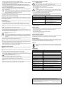
Available settings of the respective programming function (programming card = “VALUE” indicator)
1 2 3 4 5 6 7 8 9
#
Programming function
(programming card = “ITEM” indicator)
LED ashes (+ beeps) 1x short 2x short 3x short 4x short 1x long
1x long,
1x short
1x long,
2x short
1x long,
3x short
1x long,
4x short
1 Driving mode 1x short
Forwards/
brake
Forward/
braking/
reversing
Forward/
reverse
2 Battery type 2x short LiPo NiMH
3 Low voltage protection 3x short Off Low Middle High
4 Start drive power when driving forward 4x short 0% 2% 4% 6% 8% 10% 12% 14% 16%
5 Max. forward speed 1x long 25% 50% 75% 100%
6 Max. reverse speed 1x long, 1x short 25% 50% 75% 100%
7 Max. brake force 1x long, 2x short 0% 12.5% 25% 37.5% 50% 62.5% 75% 87.5% 100%
8 Start brake force 1x long, 3x short 0% 6.25% 12.5% 18.75% 25% 31.25% 37.5% 43.75% 50%
9 Brake 1x long, 4x short 0% 5% 10% 50% 60% 70% 80% 90% 100%
10 Motor brake rate 2x long 1 (min.) 2 3 4 5 6 7 8 9 (max.)
11 Neutral range 2x long, 1x short 0.02 ms 0.03 ms 0.04 ms 0.05 ms 0.06 ms 0.07 ms 0.08 ms 0.1 ms 0.12 ms
12 Start mode 2x long, 2x short 1 (min.) 2 3 4 5 6 7 8 9 (max.)
13 PWM frequency 2x long, 3x short 1 kHz 2 kHz 4 kHz 8 kHz 16 kHz
14 BEC voltage 2x long, 4x short 6 V 7.4 V
15 Free wheel 3x long On Off

• Function #12, red LED ashes twice long and twice briey: Start mode
The vehicle will start to move with more or less force depending on the setting. For a crawler, a low setting
should be selected to allow a smooth start of the vehicle.
• Function #13, red LED ashes twice long and thrice briey: PWM frequency (clock frequency)
A higher setting allows more sensitive control of the speed controller; however, the speed controller warms
up more due to the higher PWM frequency.
• Function #14, red LED ashes twice long and four times briey: BEC voltage
Here you can set the BEC voltage (output voltage of the speed controller for the power supply of the
receiver and steering servo).
For safety reasons, always use the 6 V setting if you are unsure whether the receiver and steer-
ing servo allow the higher setting. Setting the voltage too high may damage the receiver or the
steering servo and thus result in a loss of warranty/guarantee!
• Function #15, red LED ashes thrice long: Free wheel
For crawler vehicles, this function should be turned on to enable a linear driving behaviour at low speeds.
Adjusting the neutral and full throttle setting
If the vehicle does not stay stationary when the throttle/brake lever is in the neutral position, you can adjust
the throttle trim on the remote control. If the trim is insufcient (or if the trim is almost in the end position),
you can reset the trim accordingly.
Proceed as follows:
• Switch on the transmitter, leave the throttle/brake lever in the neutral position. Set the trim for the drive
function to the neutral position.
• Turn off the speed controller by pressing and holding down the on/off button for more than 0.5 seconds.
• Keep the setup button pressed and turn on the speed controller by briey pressing the on/off button.
• The red LED on the speed controller will then ash and the motor will emit beeps. Release the setup
button.
Beeps are generated by a brief activation of the motor.
• Release the throttle/brake lever on the remote control so that it is in the neutral position.
• If you press the setup button briey, the red LED on the speed controller will ash once briey and you will
then hear a beep. The neutral position has been saved.
• Move the throttle/brake lever on the transmitter to the full speed throttle position, then pull it as far as it will
go in the direction of the handle and hold it there.
Attention!
If you do not move the throttle/brake lever on the transmitter or do not move it far enough during
programming, the vehicle may respond to even minute movements of the throttle/brake lever
on the transmitter or become uncontrollable upon completion of programming. In this case,
reprogram it.
• If you press the setup button briey, the red LED on the speed controller will ash twice briey and you will
then hear two beeps. The full forwards throttle position will be saved.
• Move the throttle/brake lever to full reverse throttle (push the lever away from the handle as far as it will
go).
• If you press the setup button briey, the red LED on the speed controller will briey ash three times and
you will hear three beeps. The full reverse throttle position will be saved.
• Release the throttle/brake lever to return it to the neutral position. Wait for at least three seconds. The
speed controller will exit settings mode and apply the new settings.
Resetting the speed controller
You can reset the speed controller either via the programming card or the control buttons of the speed
controller.
When resetting via the programming card, refer to section “Programming via the supplied programming
card”.
If you want to reset the speed controller using its control buttons, proceed as follows:
• Switch on the remote control. Leave the throttle/brake lever in the neutral position, do not move it.
• Turn on the speed controller (briey press the on/off button). Wait until the speed controller has completed
a self-test and the LED stops ashing/goes off.
The speed controller must not be in programming mode.
• Now press and hold down the setup button for more than three seconds.
• The red LED on the speed controller lights up once long and a long sound signal is emitted (the sound
signal is generated by activation of the motor). Finally, the red LED ashes.
• Now turn off the speed controller by pressing and holding down the on/off button (for more than 0.5
seconds).
• With the speed controller turned on, all settings are thus reset to their default values. You now have to
programme the neutral and full throttle settings as well as make all other settings.
Getting Started with the Speed Controller
Attention, be careful!
Place the model vehicle so the drive wheels do not make contact with the ground or other
objects. Do not touch the drive mechanism, do not block it! Risk of injury!
• Switch on the transmitter and then check the rechargeable battery or battery status of the transmitter.
Release the transmitter controls, do not move them.
• Insert a drive battery into your vehicle and connect it to the speed controller.
Attention!
You should pay attention to the correct polarity of the trip controller's connection cable: Red =
Plus (+) and Black = Minus (-). If incorrectly connected, the speed controller and the recharge-
able drive battery can be destroyed! Danger of explosion/burns!
• To turn on the speed controller, briey press the on/off button.
• A red LED on the speed controller is used to display the function. Sound signals that are generated by a
short activation of the drive motor also serve for further signalling.
Meaning of the sound/LED signals Function
One short beep, LED ashes once briey NiMH vehicle battery detected
Two short beeps, LED ashes twice briey 2-cell LiPo battery detected
One long beep, LED lights up once long,
LED goes off
The speed controller has received a valid signal from the
transmitter, the throttle/brake lever is in the neutral posi-
tion, the speed controller is ready for use
LED ashes continuously The transmitter is switched off or the throttle/brake lever
is not in the neutral position
• Now check the drive and steering functions of the vehicle; observe the operating instructions for your
remote control system.
Ending operation
• Move the throttle/brake lever on the transmitter to the neutral position so that the vehicle is stationary (if
necessary, adjust the trim controller on the transmitter so that the motor stands idle).
• Switch off the speed controller.
• Disconnect the drive battery from the speed controller completely.
• Only now do you switch the transmitter off.
Excess temperature protection
If the speed controller becomes too hot, the motor will turn off. In this case, the red LED emits ashing
signals. When the speed controller cools down sufciently, it is ready for operation again.
Fail-safe function
The speed controller switches off the motor for safety reasons, if there comes no valid signal from the re-
ceiver. In this case, the red LED ashes. If your transmitter/receiver has its own fail-safe function, programme
it correctly! Check this function so that it works correctly in the event of failure.
Disposal
Electronic devices are recyclable waste and must not be disposed of in the household waste.
At the end of its service life, dispose of the product in accordance with applicable regulatory
guidelines.
Technical data
Number of cells NiMH 5 -9
Number of cells LiPo 2 - 3
Continuous current 80 A
Max. current (<1 sec.) 400 A
BEC 6 V/DC or 7.4 V (switchable), max. 3 A
Low voltage shut-off yes (can be switched off)
Excess temperature switch-off yes
Fail-safe function yes
Motor limit for 2-cell LiPo or 6-cell
NiMH
Motor type 540/550, ≥10 turns (or <30000 rpm at 7.4 V)
Motor limit for 3-cell LiPo or 7 to
9-cell NiMH
Motor type 540/550, ≥16 turns (or <20000 rpm at 7.4 V)
Connector system for receiver JR
Programming connection yes (programming card/cable included)
Dimensions (L x W x H) approx. 36.2 x 31.6 x 17 mm
Weight with cable approx. 58.5 g
This is a publication by Conrad Electronic SE, Klaus-Conrad-Str. 1, D-92240 Hirschau (www.conrad.com).
All rights including translation reserved. Reproduction by any method, e.g. photocopy, microlming, or the capture in
electronic data processing systems require the prior written approval by the editor. Reprinting, also in part, is prohibited.
This publication represent the technical status at the time of printing.
Copyright 2019 by Conrad Electronic SE. *1991061_V1_0919_02_VTP_m_en
-
 1
1
-
 2
2
-
 3
3
-
 4
4
-
 5
5
-
 6
6


Reely 1991061 Bedienungsanleitung
- Kategorie
- Ferngesteuertes Spielzeug
- Typ
- Bedienungsanleitung
- Dieses Handbuch ist auch geeignet für
in anderen Sprachen
- English: Reely 1991061 Operating instructions
Verwandte Papiere
-
 Reely 1399921 Bedienungsanleitung
-
 Reely 1600323 Bedienungsanleitung
-
 Reely 1851824 Bedienungsanleitung
-
 Reely 1456605 Bedienungsanleitung
-
Conrad Reely 1970153 Bedienungsanleitung
-
 Reely 1456606 Bedienungsanleitung
-
 Reely 1600322 Bedienungsanleitung
-
 Reely 2103649 Benutzerhandbuch
-
 Reely 1408946 Operating Instructions Manual
-
 Reely 1516009 Bedienungsanleitung


