
Teile-Nr./ Part-No.:
0791 767771
Printed in Federal Republic of Germany
Ausgabe/Edition:
01. 2006
Blatt: von
Sheet: 1 from 20
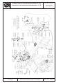
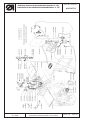
1. Komponenten der Einrichtung
Der Teilesatz 0767 590134 für den Kurzfadenabschneider (Explosionszeichnung siehe Blatt 10)
besteht aus folgenden Komponenten:
– EPROM 9800 130014 EP01
– Stichplatte 0767 200050
– Transporteur 0767 210030
– Kurvenscheibe 0767 350400
– Spulengehäuse 0767 150484
– Winkel 0767 350490
– Hubmagnet 9820 110006
– Lehrensatz 0767 290014
– Klemmfeder 0767 350410
– Fadenziehmesser 0767 350380
– Gegenmesser 0767 350390
– Diverse Kleinteile
2. Elektrischer Umbau
Ein Umbau ist nur möglich mit: Efka Nähantrieb
DC1600 DA82GA (seit 01.01.1999).
Bei anderen älteren Antrieben ist ein Umbau nur
möglich durch einen Austausch der kompletten
elektrischen Einrichtung (von 1988 bis 1998).
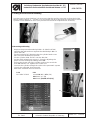
2.1 EPROM Version prüfen
Für diesen Umbausatz ist die EPROM Version von 3312 "F” - "J" oder ab 3316 "A" e rforderlich.
EPROM Abfrage Parameter 179
2.2 Parameter Einstellungen
Parameter 136 a uf 2
Parameter 154 a uf 7
Parameter 171 2. Position (einlaufende Flanke “496”)
2APosition (auslaufende Flanke “034”)
Parameter 180 Anzahl Rückdrehschritte 114
Parameter181 Einschaltverzögerung für das Rückdrehen auf 10
Parameter182 Rückdrehen auf ON
Parameter190 Einschaltwinkel des Fadenschneidens auf 300
Parameter 192 Einschaltpunkt Fadenspannung auf 310
Anleitung Umbausatz Kurzfadenabschneider Kl. 767
Instructions for the retrofit kit short thread trimmer cl. 767
Info für Ersatzteilelieferung:
Greifer komplett 0767 150504

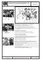
3. Mechanischer Umbau
–
Vorhandenes Fadenziehmesser, Gegenmesser und Klemmfeder mit Messerträger, Stichplatte,
Transporteur, Spulengehäuse und Kurvenscheibe ausbauen.
–
Anlagekante am Messerträger auf Maß 30,6 abfräsen (feilen) siehe Zeichnung.
–
Bei älteren Maschinen ist es möglich, daß der Guß im Greiferraum nachgearbeitet werden muß (feilen)
siehe Zeichnung.
–
Die neuen Teile in der Reihenfolge einbauen: 1. Spulengehäuse, 2. Transporteur, 3. Gegenmesser und
Klemmfeder mit abgefrästem Messerträger, 4. Stichplatte, 5. Fadenziehmesser. Zu beachten sind dabei die
Punkte im Abschnitt 4.
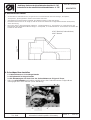
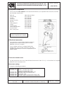
4. Schneidposition einstellen
1. Fadenziehmesser 12 ist absgechraubt
2. Stichplatte 22 ist abgeschraubt
3. Alle Klemmungen auf der Achse des Fadenziehmesser Trägers 2 lösen.
– Die Lehre 0767 290030 anschrauben und die Achse des Fadenziehmesser Trägers 2 von
unten gegen die Lehre drücken (siehe Abbildung).
Anleitung Umbausatz Kurzfadenabschneider Kl. 767
Instructions for the retrofit kit short thread trimmer cl. 767
Teile-Nr./ Part-No.:
0791 767771
Printed in Federal Republic of Germany
Ausgabe/Edition:
01. 2006
Blatt: von
Sheet: 2 from 20
3
0
,
6
+
0
,
2
0767 350020 (Fadenwächter)
0367 350040
12
2
15
22

34 12
0767 290040
3412
12
0767 290030
2
22
Teile-Nr./ Part-No.:
0791 767771
Printed in Federal Republic of Germany
Ausgabe/Edition:
01. 2006
Blatt: von
Sheet: 3 from 20
-
Die beiden Stellringe auf der Achse des Fadenziehmesser Trägers 2 axial
so fixieren, daß sich die Achse ohne Spiel leichtgängig bewegen läßt,
Stellringe fest anschrauben.
4. Lehre 0767 290040 aufschrauben
5. Positionieren des Gegenmessers 3, der Klemmfeder 4 und
des Messerträgers 1
- Den Messerträger 1 mit aufgeschraubten Gegenmesser 3 und
aufgeschraubter Klemmfeder 4 nach hinten bis zur Anlage an
den Guß und nach links bis z ur Anlage des Gegenmessers 3 an die
Lehre 0767 290040 bringen und festschrauben (siehe nebenstehende
Abbildung).
- Das Gegenmesser 3 hat dann die Position zum Tr ansporteur wie
abgebildet.
Bei stark nachgearbeiteten Greifer oder extrem dicht an der Nadel
stehendem Greifer ist es möglich daß von der Lehreneinstellung (des
Gegenmessers zum Tr ansporteur) abgewichen werden muß.
Eventuell die Befestigungsschrauben des Gegenmessers 3 lösen und das
Gegenmesser 3 im Spiel der Schraubenlöcher korrigieren. (Bei älteren oft
nachgeabeiteten G reifer ist diese Einstellung eventuell auch
nachzujustieren).
- Das Fadenziehmesser 12 anschrauben. In der hinteren Position,
Fadenziehmesser 12 steht zwischen der Klemmfeder 4 und dem
Gegenmesser 3, soll die Klemmfeder 4 den Unterfaden leicht festhalten.
Wenn nötig, die Schrauben der Klemmfeder 4 lösen und korrigieren. (Ist der
Unterfaden am Nahtanfang zu lang, siehe Fehlerbeschreibung Kapitel 7).
- Das Fadenziehmesser 12 abschrauben, die Lehre abschrauben,
die Stichplatte 22 anschrauben und das Fadenziehmesser 12 wieder mit einen
leichten Schneiddruck auf den Fadenziehmesser Träger 2 schrauben (siehe
nebenstehender Abbildung).
Kontrolle
-
Das neue Fadenziehmesser 12 muß mit der Unterseite auf der
Bogenführung 15 aufliegen. Beim bewegen des Fadenziehmessers muß
ein leichter Gegendruck spürbar sein.
Anleitung Umbausatz Kurzfadenabschneider Kl. 767
Instructions for the retrofit kit short thread trimmer cl. 767
68 119 5
710

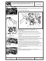
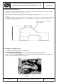
6. Die Kurvenscheibe 8 mit der Lehre 6 ausrichten. Dazu
- Den Fadenhebel in die höchste Position bringen
(Die Klemmschraube 5 ist noch gelöst, siehe Punkt 3).
- Lehre 6, wie in Abbildung dargestellt, auf die Rolle 11 stecken.
- Die Kurvenscheibe 8 in die Lehre 6 einlegen und fest anschrauben.
- Danach die Lehre 6 herausnehmen und prüfen ob alle beweglichen Teile
leicht laufen.
7. Kolbestange vom Magneten 10 einstellen.
- Kloben 7 auf der Kolbenstange des Magneten 10 lösen.
- Die Kolbenstange ganz in den Kloben 7 drehen und wieder festschrauben.
8. Die Lehre 0767 290020 anschrauben.
- Die Rolle 11 an die Kurvenscheibe 8 anlegen.
- Durch Drehen des Handrades die Kurvenscheibe 8 in die niedrigste
Position bringen. (Bei der niedrigsten Position ist die Rolle 11 am
dichtesten an der Drehachse der Kurvenscheibe 8).
Fadenziehmesser 12 liegt an der Lehre 0767 290020 an, siehe Abbildung.
- Klemmschraube 5 wieder fest anschrauben.
- Die Lehre 0767 290020 abschrauben.
9. Hebel 1 auf Welle des Fadenziehmesser Trägers 2 fest anschrauben
- Maschine mit dem Handrad so weit drehen, dass die Rolle 11 am höchsten
Punkt der Kurvenscheibe 8 anliegt.
(Bei den höchsten Punkt ist die Rolle 11 am weitesten von der Drehachse
der Kurvenscheibe 8 entfernt).
- Zwischen höchsten Punkt der Kurvenscheibe 8 und Rolle 11 einen
Abstand von 0,1 mm einstellen.
- Die Kolbenstange des Magneten 10 in Pfeilrichtung drücken und den
Hebel 1 fest anschrauben.
- Überprüfen, ob alles leicht läuft.
Anleitung Umbausatz Kurzfadenabschneider Kl. 767
Instructions for the retrofit kit short thread trimmer cl. 767
Teile-Nr./ Part-No.:
0791 767771
Printed in Federal Republic of Germany
Ausgabe/Edition:
01. 2006
Blatt: von
Sheet: 4 from 20
68 119 5
710
710
1
8
7
0767 290020

Teile-Nr./ Part-No.:
0791 767771
Printed in Federal Republic of Germany
Ausgabe/Edition:
01. 2006
Blatt: von
Sheet: 5 from 20
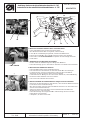
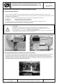
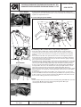
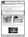
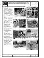
5. Kurzen Abschneidstich einstellen
Um einen kurzen Abschneidfaden zu erzeugen ist es notwendig dass die Maschine unmittelbar vor
dem Schneiden einen kurzen Stich ausführt (ca. 1 - 1,5 mm). Der kurze Stich wird erreicht durch
den Anbau eines Zylinders und eines zusätzlichen Ventils (siehe Fotos unten und Ersatzteileliste
Blatt 10).
5.1 Anbau und Einstellung
– Den vorhandenen Gewindestift M8 x 12 (9205 102798) zur
Befestigung des Riemenspanners ersetzen durch Gewindestift
M8 x 8 (9205 102778).
– Den Winkel 0767 350490 mit Zylinder-Schraube M8 x 10
(9203 004568) an dieser Bohrung befestigen,
Zylinder 0999 220747 am Winkel befestigen.
– Durch verdrehen des Stellrades 19 und Einstellen der
Kolbenstange, Schneidstich auf 1,5 mm einstellen.
– Kolbenstange des Zylinders ganz herausziehen und mit den
Muttern bis auf den Hebel 14 stellen.
– Zylinder anschließen. (Explosionszeichnung siehe Blatt 10)
– Magnetventil an der Leiterplatte der Gestellverteilung
anschliessen.
Leiterplatte PIN
Nr. 9850 767013 + und FW (NP) / STL (FA)
X26 PIN 1 oder 2 (+)
X26 PIN 6 [FW/NP/STL(FA)]
Anleitung Umbausatz Kurzfadenabschneider Kl. 767
Instructions for the retrofit kit short thread trimmer cl. 767
19
14

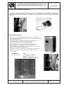
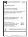
6. Anbau der Fadenklemme (Fadeneinzugseinrichtung)
6.1 Allgemeine Informationen
Mit der Fadenklemme 15 und der dazugehörenden Elektronik wird der Oberfaden beim Annähen nach unten
gezogen und verschlungen. Damit der Faden nicht reißt, (er kann zwischen Fuß und Material eingeklemmt sein) wird
der Nähfuß kurzzeitig entlastet.
Die Stärke der Entlastung ist gekoppelt m it der Position des St ellrades 20 (Hubverstellung).
Höhere Hub stärkere Entlastung (dickeres Material)
Niedriger Hub weniger Entlastung (dünneres Material)
Die richtige Funktion der Fadenklemme ist abhängig von der Einstellung des Potentiometers 3.
Im Normalfall ist dieses Potentiometer richtig eingestellt.
ACHTUNG!
Bei Beginn des Nähprozesses (nach dem Einfädeln des Oberfadens und dem
Einlegen einer neuen Spule) ist darauf zu achten, daß die Fadenlänge die normale
Abschneidlänge hat (ca. 28 mm). Mit der Schere kürzen!!!
Bei Nichtbeachten besteht die Gefahr eines Einschlagens des Fadens in die Greiferbahn
und somit Bruch des Greifers bzw. der Stichplatte!
6.2 Kontrolle/Einstellung des Potentiometers (wenn notwendig)
Die Nähmaschine ist mit einem Potentiometer zur Begrenzung der Drehzahl bei größeren Hüben
und zur Füßchenentlastung ausgestattet. Das Potentiometer 3 ist über Welle 2, Hebel 1, und
Kugelbolzen mechanisch mit dem Stellrad auf dem Armdeckel verbunden. Über Potentiometer 3
erkennt die Steuerung den eingestellten Nähfußhub und paßt die Stichzahl sowie die Dauer der
Fußentlastung für die Fadeneizugseinrichtung an.
Anleitung Umbausatz Kurzfadenabschneider Kl. 767
Instructions for the retrofit kit short thread trimmer cl. 767
Teile-Nr./ Part-No.:
0791 767771
Printed in Federal Republic of Germany
Ausgabe/Edition:
01. 2006
Blatt: von
Sheet: 6 from 20
43
12
15
20
11
12

Teile-Nr./ Part-No.:
0791 767771
Printed in Federal Republic of Germany
Ausgabe/Edition:
01. 2006
Blatt: von
Sheet: 7 from 20
Regel und Kontrolle
Justage des Potentiometers 1 kontrollieren
–
Taste “P” gedrückt halten, Hauptschalter einschalten, Code-Nr. eingeben und Parameter F-188
anwählen.
– Taste “E” drücken; Die aktuelle Speedomatstufe und die zugehörige Drehzahlbegrenzung werden
angezeigt.
– Beim Verstellen der Hubhöhe mit dem Einstellrad auf die minimale Hubhöhe sollte im Display
eine Speedomatstufe zwischen 1 und 3 angezeigt werden.
– Beim Verstellen der Hubhöhe mit dem Einstellrad auf die maximale Hubhöhe sollte im Display
eine Speedomatstufe zwischen 19 und 21 angezeigt werden.
– Andernfalls muß das Potentiometer neu justiert werden.
Potentiometer 1 justieren
– Nach dem Einbau des Potentiometers muß die Potentiometerachse in der Hubwelle justiert
werden. Bei der Verwendung der Nähantriebe DC 1600/DA82GA und des Bedienfeldes V810 oder
V820 erfolgt die Einstellung mit dem Parameter F-188. Man geht wie folgt vor:
– Armdeckel entfernen und mit der Hubwelle die geringste Hubhöhe einstellen.
– Arretierschraube für die Potentiometerwelle lösen
– Taste “P” gedrückt halten, Hauptschalter einschalten, Code-Nr. eingeben und Parameter F-188
anwählen.
Bedienfeld V810
– Bei Anwendung des Bedienfeldes V810 Anzeige V810
– Taste “E” drücken; Die aktuelle Speedomatstufe (z.B. 11) und die 11.2400
zugehörige Drehzahlbegrenzung (z.B. 2400) werden angezeigt.
– Die Potentiometerachse wird (an den Greifringen) gedreht, 01.3500
bis in der Anzeige die Speedomatstufe “01” und die zugehörige
Maximaldrehzahl (z. B. 3500) angezeigt wird.
– Die Potentiometerwelle mit der Arretierschraube festziehen.
– Armdeckel montieren und die Einstellung kontrollieren.
Bedienfeld V820
– Bei Anwendung des Bedienfeldes V820 Anzeige V820
– Taste “E” drücken; Die aktuelle Speedomatstufe (z.B. 11) und die 2400 05 11 19
zugehörige Drehzahlbegrenzung (z.B. 2400) werden angezeigt.
– Die Potentiometerachse wird (an den Greifringen) gedreht, 3500 05 01 19
bis in der Anzeige die Speedomatstufe “01” und die zugehörige
Maximaldrehzahl (z.B. 3500) angezeigt wird.
– Die Potentiometerwelle mit der Arretierschraube festziehen.
– Armdeckel montieren und die Einstellung kontrollieren.
Achtung!
Das Justieren des Potentiometers erfolgt bei eingeschaltetem Hauptschalter.
Es muß mit entsprechender Vorsicht gearbeitet werden!
Anleitung Umbausatz Kurzfadenabschneider Kl. 767
Instructions for the retrofit kit short thread trimmer cl. 767

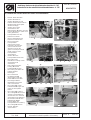
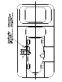
6.3 Elektrischer und mechanischer Anbau der Fadenklemme
–
Deckel 1 abschrauben.
–
Stecker 2 abziehen.
–
Stecker 3 abziehen und
Kabelschelle 4 abschrauben
(Kabelschelle wird später
wieder benötigt).
–
Stecker 7 aus dem
Steuerkasten des
Nähantriebes 8 ziehen und die
Leitung 5 entfernen (wird nicht
mehr gebraucht)
–
Leiterplatte 6 von den
Rastnasen ziehen.
–
Neue Leiterplatte 9 auf
Rastnasen aufstecken.
–
Die auf der alten
Leiterplatte 6
angeschlosssenen
Leitungen der Stecker
X23 bis X26 einzeln
abziehen und an die
gleiche entschprechende
Stelle auf der neuen
Leiterplatte 9
anschließen.
–
Stecker 2 an die
Leiterplatte 9 anstecken.
– Die im Bausatz
befindliche Leitung in den
Steuerkasten 8
einstecken.
–
Das andere Ende der
Leitung 10 auf die
Leiterplatte 9 stecken.
–
Die Leitung mit Hilfe der
Kabelschelle 4
befestigen.
–
Die vorhandene
Fadenführung 15
abschrauben und den
Halter 16 anschrauben.
–
Den Magnet 17 zur
Nadelmitte ausrichten
und anschrauben.
–
Die Leitung 11 in den
Kabelkanal 12 legen und
unter die Tischplatte
führen.
–
Die Leitung 11 entlang
der Leitung 13 führen und
auf der Leiterplatte 9 an
die Stecker X27 und X28
anschließen. Mit Hilfe der
im Bausatz befindlichen
Kabelbinder 14 die
Leitung 11 an der
Leiterplatte 9 und entlang
der Leitung 13 fixieren.
–
Deckel 1 wieder
anschrauben.
Anleitung Umbausatz Kurzfadenabschneider Kl. 767
Instructions for the retrofit kit short thread trimmer cl. 767
Teile-Nr./ Part-No.:
0791 767771
Printed in Federal Republic of Germany
Ausgabe/Edition:
01. 2006
Blatt: von
Sheet: 8 from 20
1
2
643 5alt 9 (9850 767013)
410131114
914
16
17
15
7
8
11
12

Teile-Nr./ Part-No.:
0791 767771
Printed in Federal Republic of Germany
Ausgabe/Edition:
01. 2006
Blatt: von
Sheet: 9 from 20
7. Mögliche Fehler, Ursache und Abhilfe
Fehler Ursache und Abhilfe
Faden wird
nicht geschnitten
-Parameter prüfen
-Messer stumpf oder Fehlerhaft
-Schneiddruck Fadenziehmesser-Gegenmesser
-Position Fadenziehmesser (siehe Punkt 4)
-Kurvenscheibe:
Die Höhe des Fadenziehmessers zum Gegenmesser prüfen
Oberfadenzukurz -Vorspannung zu stark
-Kurvenscheibe zu früh (siehe Punkt 4)
Fadenklemme
klemmt nicht
-Fremdkörper in der Fadenführung
-Parameter prüfen
-Anschluß an der Platine prüfen (siehe Punkt 6.3)
Oberfaden wird
nicht nach unten
gezogen oder der
Faden reißt am
Nahtanfang
-Parameter prüfen
-Hubverstellung prüfen
-Füßchenlüftung zu langsam
-Drossel prüfen
-Fadenklemme klemmt nicht
-Anschluß an der Platine prüfen
Fadenziehmesser
fängt den Faden nicht
-Position der Kurvenscheibe kontrollieren
-Fadenziehmesser nicht leichtgängig
-Fadenziehmesser nicht in Ausgangsposition
-Einstellung prüfen (siehe Punkt 4)
-Fadenziehmesser zu hoch (siehe Punkt 4)
Fadenziehmesser
wird nicht in die
Fangposition
gebracht
-Magnet nicht richtig eingestellt (siehe Bemerkung Punkt 4)
-Druck des Gegenmessers zu stark (siehe Punkt 4)
Unterfaden ist zu
lang am Anfang
-Die Klemmfeder hält den Unterfaden zu stark fest.
-Klemmfeder loser stellen.
Hinweis!
Durch Nachschleifen des Gegenmessers werden die Fadenabschnitte
länger!
Anleitung Umbausatz Kurzfadenabschneider Kl. 767
Instructions for the retrofit kit short thread trimmer cl. 767

Anleitung Umbausatz Kurzfadenabschneider Kl. 767
Instructions for the retrofit kit short thread trimmer cl. 767
Teile-Nr./ Part-No.:
0791 767771
Printed in Federal Republic of Germany
Ausgabe/Edition:
01. 2006
Blatt: von
Sheet: 10 from 20

Teile-Nr./ Part-No.:
0791 767771
Printed in Federal Republic of Germany
Ausgabe/Edition:
01.2006
Blatt: von
Sheet: 11 from 20
1. Equipment components
The set of parts 0767 590134 of the short thread trimmer (see exploded view sheet 20) includes
the following components:
– EPROM 9800 130014 EP01
– Throat plate 0767 200030
– Feeder 0767 210030
– Cam disk 0767 350400
– Bobbin housing 0767 150484
– Bracket 0767 350430
– Lifting magnet 9820 110006
– Gauge 0767 290014
– Clamp spring 0767 350410
– Thread-pulling knife 0767 350380
– Counter knife 0767 350390
– Misc. small parts
2. Electrical conversion
A conversion is only possible with the machines
equipped with the Efka Sewing drive DC1600
DA82GA (since 01.01.1999).
If your sewing machine is equipped with older
sewing drive, carry out the conversion only after
changing completely the electrical equipment (from
1988 to 1998)
2.1 Check the EPROM version
For the present kit is the use of the EPROM fromVersion 3312 “F” to "J" or from 3316 "A" required.
EPROM check Parameter 179
2.2 Parameter settings
Change the following parameters:
Parameter 136 t o 2
Parameter 154 t o 7
Parameter 171 Position 2 (leading edge “496”)
Position 2A(trailing edge “034”)
Parameter 180 Number of reversion increments 114
Parameter 181 Activation delay of reversion 10
Parameter 182 R ev er si on “ON”
Parameter 190 Activation angle of the thread trimmer 300
Parameter 192 Activation angle of thread tension release 310
Anleitung Umbausatz Kurzfadenabschneider Kl. 767
Instructions for the retrofit kit short thread trimmer cl. 767
Info for Spare parts:
Bobbin complete 0767 150504

3. Mechanical conversion
–
Dismantle the existing thread-pulling knife, the counter knife with the clamp spring and the knife support,
throat plate, feeder, bobbin housing and the cam disc.
–
Mill off the contact edge at its support (file) to measure 30,6 (see drawing).
–
With older machines, it may be necessary to rework (file) the cast iron in the vicinity of the hook, see
drawing.
–
Mount the new parts in t he following order: 1
st
bobbin housing, 2
nd
feeder, 3
rd
counter knife with its support
milled off and clamp spring, 4
th
throat plate, 5
th
thread-pulling knife. Please pay attention to the points
described in the subheading 4.
4. Setting the cutting position
1. The thread-pulling knife 12 is screwed off .
2. The throat plate screwed off .
3. Loosen all the clamping on the axis of the thread-pulling knife support 2.
– Screw on the gauge 0767 290030 and turn the axle of the thread-pulling knife support 2 from the
bottom to press against the gauge (see picture).
Anleitung Umbausatz Kurzfadenabschneider Kl. 767
Instructions for the retrofit kit short thread trimmer cl. 767
Teile-Nr./ Part-No.:
0791 767771
Printed in Federal Republic of Germany
Ausgabe/Edition:
01. 2006
Blatt: von
Sheet: 12 from 20
3
0
,
6
+
0
,
2
0767 350020 (thread monitor)
0367 350040
12
2
15
22

Teile-Nr./ Part-No.:
0791 767771
Printed in Federal Republic of Germany
Ausgabe/Edition:
01. 2006
Blatt: von
Sheet: 13 from 20
-
Screw on both adjustment discs on the axle of the thread-pulling knife
support 2 in such a way that the axle can be smoothly moved without play.
Tighten the adjustment discs.
4. Screw on the gauge 0767 290040
5. Positioning of the counter knife 3, clamp spring 4 and support 1
- Push t he support 1 with the counter knife 3 and the clamp spring 4
screwed on to the rear until it touches the cast iron and then to the left
until the counter knife 3 touches the gauge 0767 290040 (see opposite
picture).
- The counter knife 3 is then positioned as seen on the opposite picture.
If the hook has been often reworked or the needle is standing extremely
close t o the hook it may be necessary to deviate from the gauge setting
(the counter knife to the feeder).
Eventually, loosen the fastening screws of the counter knife 3 and correct the
clearance through shifting it within the r oom left by the bolt holes. (It may be
necessary to redo the setting again with older and often reworked hooks).
- Screw on the thread-pulling knife 12. Turn the thread-pulling k nife 12 and
its support 2 to the rear, to be between the clamp spring 4 and the counter
knife 3. The clamp spring 4 should retain lightly the bobbin thread. If
necessary loosen the screws of the the clamp spring 4 and set it again. (If the
bobbin thread is too long at the seam beginning, check the error description
at chapter 7).
- Screw off the thread-pulling knife 12, screw off the gauge, screw on the
throat plate 22 and then the thread-pulling knife 12 (see opposite picture).
In this position, press the thread-pulling k nife 12 to the left (make sure to
have a small cutting pressure) and screw it on.
Control
- Check whether the lower surface of the thread-pulling knife 12 rests upon the
curved guide 15. When moving the thread-pulling knife 12 a light
counter-pressure must be noticeable.
Anleitung Umbausatz Kurzfadenabschneider Kl. 767
Instructions for the retrofit kit short thread trimmer cl. 767
68 119 5
710
34 12
0767 290040
3412
12
0767 290030
2
22

6. Align the trimmer disc 8 with the gauge 6. For that purpose:
- Set the thread lever t o its highest position
(the clamping screw 5 is still unfastened see 3
rd
point).
- Insert the gauge 6 to the roll 11 as represented in the picture.
- Insert the thread trimmer disc 8 in the gauge 6 and fasten it.
-Afterwardsremove the gauge 6 and check whether all moving parts are
running smoothly!
7. Set the piston rod of the magnet 10.
- Loosen the block 7 on the piston r od of the m agnet 10.
- Twist the piston rod completely on the block 7 and tighten it.
8. Screw on the gauge 0767 290020
- Position the roll 11 against the disc 8.
- Position the trimmer disc 8 to its lowest position by turning the handwheel.
(Lowest position: where the roll 11 comes closest to the to the axis
of rotation of the disc 8). The thread pulling knife abuts on the
gauge 0767 290020, see picture.
- Tighten the clamping screw 5 again.
- Screw off the gauge 0767 290020.
9. Tighten the lever 1 to the shaft of the thread-pulling knife support 2
- Tu rn the machine using the handwheel, so that the roll 11 clings to the
highest point of the t hread trimmer disc 8.
(Highest position: where the roll 11 is furthest from the axis of rotation of
the t hread trimmer disc 8).
- There should be a clearance of 0.1 mm between the roll 11 and the peak
of the trimmer disc 8.
- Press the rod of t he magnet 10 downward in the direction of the arrow and
tighten the clamping screw 1 in this position.
-
Check whether all moving parts are running smoothly!
Anleitung Umbausatz Kurzfadenabschneider Kl. 767
Instructions for the retrofit kit short thread trimmer cl. 767
Teile-Nr./ Part-No.:
0791 767771
Printed in Federal Republic of Germany
Ausgabe/Edition:
01. 2006
Blatt: von
Sheet: 14 from 20
710
68 119 5
710
1
8
7
0767 290020

Teile-Nr./ Part-No.:
0791 767771
Printed in Federal Republic of Germany
Ausgabe/Edition:
01. 2006
Blatt: von
Sheet: 15 from 20
5. Setting the short stitch trimming
In order to get a short trimming, it is necessary that the machine executes a short stitch right
before cutting (approx. 1 - 1.5 mm). The short stitch will be achieved by the mounting of a new
cylinder and an additional valve (see pictures below and the exploded view sheet 20).
5.1 Mounting and Setting
– Replace the present threaded pin M8 x 12 (9205 102798)
retaining the belt tensioner against the threaded pin M8 x 8
(9205 102778).
– Fix the bracket 0767 350490 using the cylinder head screw
M8 x 10 (9203 004568) on the hole.
Fix the cylinder 0999 220747 onto the bracket.
– Set the stitch trimming to approx. 1.5 mm by adjusting the
piston rod and turning the setting wheel 19.
– Pull out the piston rod of the cylinder and set it to touch the
lever 14 with the nut. Tighten the c ounter nut.
– Connect the cylinder through the valve to the pneumatic system
(check the exploded view sheet 20).
– Attach the solenoid valve to the PCB.
PCB PIN
No. 9850 767013 + and FW (NP) / STL (FA)
X26 PIN 1 or 2 (+)
X26 PIN 6 [FW/NP/STL(FA)]
Anleitung Umbausatz Kurzfadenabschneider Kl. 767
Instructions for the retrofit kit short thread trimmer cl. 767
19
14

6. Mounting the thread clamp (Thread feeding device)
6.1 General Informations
With the thread clamp 15 and the r elevant electronic components, the thread is pulled downward and
swallowed up while sewing on. In order to avoid a threadbreakage (the thread can get jammed between the
sewing foot and material) the sewing foot is briefly relieved.
The strength of the relief depends on the position of the adjusting wheel 20 (stroke adjustment).
Higher stroke stronger relief (thicker Material)
Lower stroke weaker relief (thinner Material)
The correct function of the thread clamp depends on the setting of the potentiometer 3.
The potentiometer is in general correctly set.
ATTENTION!
When starting the sewing process (after the threading the upper thread/inserting a new
bobbin), make sure that the t hread has the normal thread length (apporx. 28 mm). Cut it
using a pair of scissors!!!
Ignoring the above may lead to the danger of the thread wrapping the shuttle track thus
breaking the hook and/or the throat plate!
6.2 Control/Adjustment of the potentiometer (if necessary)
The sewing machine is equipped with a potentiometer for speed limitation in case of higher strokes and relieving
the sewing f oot.
The potetiometer 3 is mechanically connected with the setting wheel on the arm cover via shaft 2,
lever 1 and ball pin. The control recognizes t he set sewing foot stroke through the potentiometer 3 and adapts the
number of stitches and the thread f eed for t he thread feeding device.
Anleitung Umbausatz Kurzfadenabschneider Kl. 767
Instructions for the retrofit kit short thread trimmer cl. 767
Teile-Nr./ Part-No.:
0791 767771
Printed in Federal Republic of Germany
Ausgabe/Edition:
01. 2006
Blatt: von
Sheet: 16 from 20
43
12
15
20
11
12

Teile-Nr./ Part-No.:
0791 767771
Printed in Federal Republic of Germany
Ausgabe/Edition:
01. 2006
Blatt: von
Sheet: 17 from 20
Rule and control
Checking the adjustment of the potentiometer 1
–
Hold the “P” key down, turn the main switch on, enter the code no. and select parameter F-188.
– Press the “E” key. The current Speedomat level and the c orresponding speed limitation are
displayed.
– When setting the stroke height with the setting dial to the minimum stroke height the display
should show a Speedomat level between 1 and 3.
– When setting the stroke height with the setting dial to the maximum stroke height the display
should show a Speedomat level between 19 and 21.
– If not, the potentiometer must be readjusted.
Adjusting potentiometer 1
– After the attachment of the potentiometer the potentiometer axle in the stroke shaft must be
adjusted. When using the sewing drive DC1600/DA82GA or VD552KV/6F82FA and the control
panel V810 or V820 the setting occurs via the parameter F-188. Proceed as follows:
– Remove the arm cover and set the smallest stroke height with the stroke shaft.
– Loosen the arresting screw for the potentiometer shaft
– Hold the “P” key down, turn the main switch on, enter the code no. and select parameter F-188.
V810 control panel
– Using the V810 control panel Display V810
– Press the “E” key; The current Speedomat level (e.g. 11) and 11.2400
the corresponding speed limitation (e.g. 2400) are displayed.
– The potentiometer axle is turned (at the gripper rings) 01.3500
until the display shows the Speedomat level “01" and
the corresponding maximum speed (e.g. 3500).
– Tighten the potentiometer shaft with the arresting screw.
– Remount the arm cover and check the setting.
V820 control panel
– Using the V820 control panel Display V820
– Press the “E” key; The current Speedomat level (e.g. 11) and the 2400 05 11 19
corresponding speed limitation (e.g. 2400) are displayed.
– The potentiometer axle is turned (at the gripper rings) 3500 05 01 19
until the display shows the Speedomat level “01" and
the corresponding maximum speed (e.g. 3500).
– Tighten the potentiometer shaft with the arresting screw.
– Remount the arm cover and check the setting.
Attention!
The adjustment of the potentiometer occurs with the main s witch turned on.
Work must thus be conducted with appropriate caution!
Anleitung Umbausatz Kurzfadenabschneider Kl. 767
Instructions for the retrofit kit short thread trimmer cl. 767

6.3 Mounting the electrical and mechanical parts the thread clamp
–
Unscrew the cover 1.
–
Unplug the connector 2.
– Pull out the plug 3 and
unscrew the cable tie 4
(keep it for a later use).
– Pull out the plug 7 from the
control box of the sewing
drive 8 and remove the
cable 5 (no longer needed).
– Remove the PCB 6 from the
clips
– Attach the new PCB 9 to the
clips.
– Unplug the cables of the
plugs X23 to X26 one by
one, connected to the
old PCB 6, and connect
them to the PCB 9.
– Plug the connector 2 to
the PCB 9.
– Plug the cable provided
with the kit into the
control box 8.
– Plug the other end of
the cable 10 to the
PCB 9.
– Attach the cable using
thecabletie4.
– Unscrew the existing
thread guide 15 and
screw on the
support 16.
– Align the clamping
magnet 17 with the
centre of the needle and
screw it on.
– Lead the cable 11
through the cable
duct 12 under the table
top.
– Lead the cable 11 along
the cable 13 and attach
the
plugs to the PCB 9
X27 and X28. Fix the
cable 11 using the
provided cable
ties 14 at the PCB 9.
– Screw on the c over 1
again.
Anleitung Umbausatz Kurzfadenabschneider Kl. 767
Instructions for the retrofit kit short thread trimmer cl. 767
Teile-Nr./ Part-No.:
0791 767771
Printed in Federal Republic of Germany
Ausgabe/Edition:
01. 2006
Blatt: von
Sheet: 18 from 20
7
8
1
alt 9 (9850 767013)
2
643 5
410131114
914
15
16
17
11
12

Teile-Nr./ Part-No.:
0791 767771
Printed in Federal Republic of Germany
Ausgabe/Edition:
01. 2006
Blatt: von
Sheet: 19 from 20
7. Errors, Cause and Remedy
Error Cause and Remedy
The thread does
not get cut
-Check parameter
-Knife dull or faulty
-Cutting pressure pulling-knife/counter-knife
-Thread-pulling knife position (see chapter 4)
-Trimmer disc
-Check the height of the thread-pulling knife to the counter
knife
Upper thread
too short
-Pretension too strong
-Trimmer disc too early (see chapter 4)
The thread clamp
does not clamp
-Dirt particle in the thread guide
-Check parameter
-Check connection to the PCB (see chapter 6.3)
The upper thread
is not pulled
downward or
the thread breaks
while sewing on
-Check parameter
-Check the stroke adjustment
-Sewing foot lift too slow
-Check throttle
-The thread clamp does not clamp
-Check connection to the PCB
The thread-pulling
knife does not
catch the thread
-Check the position of the trimmer disc
-Thread-pulling knife not smoothly moving
-Thread-pulling knife not in output position
-Check setting (see chapter 4)
-Thread-pulling knife too high (see c hapter 4)
The thread-pulling
knife will not be taken
to its catching position
-Magnet not set properly (see remark chapter 4)
-Too strong pressure of the counter knife (see chapter 4)
Too long bobbin thread
at the beginning
-The clamp spring is retaining the bobbin thread too strongly
-Set the clamp spring to be less tight.
Hint!
The regrinding of the c ounter knife will result in lengthening the threads cut!
Anleitung Umbausatz Kurzfadenabschneider Kl. 767
Instructions for the retrofit kit short thread trimmer cl. 767

Anleitung Umbausatz Kurzfadenabschneider Kl. 767
Instructions for the retrofit kit short thread trimmer cl. 767
Teile-Nr./ Part-No.:
0791 767771
Printed in Federal Republic of Germany
Ausgabe/Edition:
01. 2006
Blatt: von
Sheet: 20 from 20
Seite wird geladen ...
-
 1
1
-
 2
2
-
 3
3
-
 4
4
-
 5
5
-
 6
6
-
 7
7
-
 8
8
-
 9
9
-
 10
10
-
 11
11
-
 12
12
-
 13
13
-
 14
14
-
 15
15
-
 16
16
-
 17
17
-
 18
18
-
 19
19
-
 20
20
-
 21
21


in anderen Sprachen
- English: DURKOPP ADLER 767 User manual
Verwandte Artikel
-
DURKOPP ADLER 767 Benutzerhandbuch
-
-
-
-
-
-
-
-
-