Hitachi HA-3800 Benutzerhandbuch
- Kategorie
- Musikinstrumentenverstärker
- Typ
- Benutzerhandbuch

No. 262EGF
HA-3SOO
CONTENTS
SPECTFICAT|ONS
.........1
FEATURES.
...........1
ADJUSTMENT....
.........3
DESCRIPTION
OF
THE
NEW
CIRCUITS.. .....4
CHECKING
OF
THE
OPERATION
OF
THE
PROTECTTON CrRCU rT ....
.........6
CIRCUIT DIAGRAM
......9
PRINTED WIRING BOARD
.........10
DISASSEM BLY AND REPLACEMENT.
.,.....12
REPLACEMENT PARTS
LIST
......14
FRONTAND REAR PANEL...
......17
SAFETY PRECAUTION
The
following
precautions
should be
observed when
servicing.
1.
Since many
parts
in
the
unit
have special
safety related
characteristics, always use
genuine
Hitachi's
replacement
parts.
Especially
critical
parts
in
the
power
circuit block should
not
be replaced
with other makers.
Critical
parts
are marked with
A
in
the
schematic
diagram
and circuit board diagram.
2. Before returning
a repaired unit
to the
customer,
the service technician must
thoroughly
test the
unit
to ascertain
that it is
completely
safe to
operate
without
danger
of
electrical
shock.
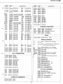
SPECIFICATIONS
Power
output
(Both
channels driven)
Power
bandwidth
Frequency
characteristics
TUNER, TAPE
PHONO
Harmonic
distortion
(8
ohmsl
(at
rated
output)
/.\
lat1l2
rated
outputl
I
ntermodulation distortion
latl/2
rated
output)
I
nput sensitivity/
lmpedance
PHONO
TUNER,
AUX
TAPE PLAY
'
Output level
TAPE REC
OUT
35 watts*
per
channel,
min. RMS
at
8
ohms
from 20 Hz
to
20
kHz,
with no
more
than 0.05% total hormonic
distortion.
35W/ch
+
35W/ch
(8
0hms, 1 kHz,
T.H.D.
0.05%)
35W/ch +
35W/ch
(4
ohms, 1 kHz,
T.H.D.0.05%)
10
Hz
-
30
kHz
(8
ohms,
l12Rated
T.H.D.0.1%)
20 Hz
-
70 kHz
(+0.5,
-3.0
dB)
RIAA
+
O.sdB
Less than 0.05%
Les
than 0.05%
Less than 0.05o/o
2.5 mY/47 k-ohms
'150
mV/40 k-ohms
150
mV/zl0
k-ohms
150 mV
Phono
overload level
Signal-to-noise
ratio
(lHF
A
PHONO
TUNER,
AUX, TAPE
Damping factor
Bass
control
Treble
control
Loudness
control
Subsonic filter
Power
supply
Power
consumption
Dimensions
Weight
200
mV
(at
1 kHz)
networkl
80 dB
100
dB
30
(1
kHz,
8
ohms)
+8
og
(1oo
Hz)
+8
da
(10
kHz)
+6
dB
(100
Hz)
+4
dB
(10
kHz)
20 Hz
AC 120
V 60 Hz,
-220
V filffi
Hz,
-240
V
50/60 Hz
or
-120
V
1220
V
I
240Y
filffi Hz
110 W
(at
1/10 rated
output)
180
W
(at
1/3
rated
output)
300 W
(at
rated
output)
zt35(W)
x83(H) x299(D)
mm
5.8 kg
FEATU RES
1.
Super linear
circuit
for low
switching
distor-
tion.
2. Equalizer
circuit with
high sens:tivity
and
S/N ratio.
3. 14 LEDs
power
indication.
Measured
pursuant
to the
Federal Trade Commission's
Trade Regulation
Rule
on
Power
Output
Claims for
amplifiers.
Electronic
protection
circuit.
Connection facilities
for
two
pairs
of
speakers.
Sleek and
chic design.
6.
SPECIFICATIONS
AND PARTS
ARE
SUBJECT TO
CHANGE
FOR IMPROVEMENT.
April
198
t
TOYOKAWA
WORKS
STEREO
AMPLIFIER

HITACHI
HA.38OO
TECHNISCHE
Ausgangsleistung
DIN
8 Ohm
35 Watt/Kanal
+
35
Watt/Kanal
(beide
Kanable
ausgesteuert an
8 Ohm,
20
Hz
-
20 kHz, T.H.D.
0,05o/ol
35
Watt/Kanal +
35 Watt/Kanal
(an
8 Ohm,
1 kHz, T.H.D.0,05%ol
35
Watt/Kanal
+ 35 Watt/Kanal
(an
4
Ohm. 1
kHz,
T.H.D.
0,05%)
10 Hz
-
30
kHz
(8
Ohm; Klirrgrad
0,1%;
halbe Nennleistung)
20 Hz
-
70 kHz
(+0,5,
-3.0
dB)
RlAA-Kennlinie
+
0,5 dB
Kleiner
als 0,05o/o
Kleiner
als 0,05o/o
2,5
mV/47 k-Ohm
150
mV/zl0
k-Ohm
150
mV/zl0
k-ohm
150 mV
Phonoiiberlastungspegel
200
mV
(bei
1 kHzl
G erduschspannungsabstand
(lHF,
A-Zetzl
PHONO
TUNER, AUX,
TAPE
Ddmpfungsfaktor
Tiefeneinstellung
Hdheneinstellung
Gehdrrichtige
Laustd
rkekorrektur
S ubson
icf ilter-Scha lter
Netzspannung
Leistungsaufnahme
Abmessungen
Gewicht
DATEN
DIN 4
Ohm
Leistungsbandreite
Frequenzcharakteristik
TUNER, TAPE
PHONO
Klirrfaktor
18
Ohm)
(bei
Nennleistungl
{bei
halber Nennleistungl
I ntermodulations-Verzerru
ng
(bei
halber
Nennleistungl
Kleiner als 0,05%
E ingangsempf
indichkeit/ |
mpedanz
80 dB
lm
dB
30
(1
kHz,
8
Ohm)
+8
og
(1oo
Hz)
+g
og
(10
kHz)
+6
dB
(100
Hz)
+4
dB
(10
kHz)
2O Hz
Wechselstrom
12OV
ffiHz,
-220
V A50/60
Hz,
-240
V 50/60
Hz
oder
-
120V/220V/
240Y
filffi Hz
110
W
(bei
1/10 Nennleistung)
180 W
(bei
1/3
Nennleistung)
300 W
(bei
Nennleistung)
€5(B)
x83(H) x299(T)
mm
5,8 ks
PHONO
TUNER. AUX
TAPE
PLAY
Ausgangspegel
TAPE REC
OUT
Bande
passante
Garact6ristiques
de fr6quence
TUNER,
TAPE
PHONO
Distorsion
harmonique
(8
ohmsl
(d
la
p0issance
nominalel
(i
la moiti6 de la
lpuissance
nominale)
D istorsion
d'intermodulation
ld
la
moiti6 de
la
puissance
nominalel
Sensibilit6 d'entr6e/
|
mp6dance
PHONO
TUNER,
AUX
TAPE PLAY
MERKMALE
1.
Schaltkreis
hoher Linearitdt
fiir
geringste
Schaltverzerrungen.
2. Entzerrungsschaltung
mit hoher
Empfindlichkeit
und
groBem
Fremd-
spannungsabstand.
CARACTER
ISTI
OU ES TECH
N
I
OU
ES
Puissance
de sortie
35 W/can. +
35
W/can.
(deux
canaux
en
fonction
sous
8
Ohms. 20
-
20
000 Hz, D.H.T.
0,05%)
35 W/can. +
35 W/can.
(8
ohms,
1 kHz,
D.H.T.
0,05%)
35
W/can. +
35 W/can.
(4
ohms,
1 kHz, D.H.T.0,05%l
10 Hz
-
30 kHz
(8
ohms 1/2
de
0,1"/ol
20 Hz
-
20 kHz
(+0,5,
-3,0
dB)
RIAA
+
0,5 dB
lnf6rieure
a 0,05%
lnf6rieure
a 0,05%
lnf6rieure
d 0,05o/o
2,5
mY/47 k-ohms
150 mV/40 k-ohms
150
mV/ul0 k-ohms
Anderungen
der Konstruktion
und
technischen Daten
bleiben
im
Sinne der
St6ndigen
Verbesseru
ng vorbeha lten.
3.
14
LED-Leistungskontrollen
4.
Elektronische
Schutzschaltung.
5. AnschluBmtiglichkeiten
fiir
zwei
Lautsprecher-
paare.
6. Schnittiges,
modernes Design.
Niveau
de sortie
TAPE REC
OUT
Niveau de
surcharge
phono
Rapport
signal/bruit
{lHF,
r6seau
Al
PHONO
TUNER,
AUX, TAPE
Facteur
d'amortissement
R6glage
de
graves
R69lage
des aigu6s
Correction
physiologique
Filtre
subsonique
Alimentation
Consummation
150
mV
200
mV
(d
1 kHz)
80 dB
100
dB
30
(1
kHz,
8
ohms)
+8
og
(1oo
Hz)
+8
og
(10
kHz)
+6
dB
(100
Hz)
+5
dB
(10
kHz)
20
Hz
CA
120
V 60 Hz,
-20V
50/60 Hz.
-24o
V 50/60
Hz
ou
-120Y1
220V/2q
V 50/60
Hz
110
W
(a
1/1O de
la
puissance
nominale)
180 W
(a
113
de la
puissance
nominale)
300 W
(d
la
puissance
nominale)
zl35(L)
x 83(H)
x 299(P)
mm
5,8 ks
Les
caract6ristiques
techniques
et la
pr6sentation
peuvent
6tre
modifi6es
sans
pr6avis
pour
des
raisons
d'am6lioration.
Dimensions
Poids
d'enceintes.
6. Ligne
6l6gante
et
Circuit
protecteur
6lectronique.
Possibilit6
de branchement
de
deux
paires
CARACTERISTIOUES
J.
Circuit
Super
Lin6aire
pour
Suppression
des
distorsion
de
commutation.
2.
Circuit
de
correction
d
sensibilate
et
rapport
S/B
6lev6s.
3.
lndication
de
puissance
par
14
diodes.
2
a

HITACHI
HA.38OO
A\
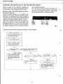
ADJUSTMENT
ldle
current adjustment
Set
the unit to no
signal, speaker select
switch
OFF,
Volume
control minimum, R761L(R)
to minimum
(counterclockwise).
Next
connect a DC
voltmeter
to
R7I4L(R)
and
turn the
power
switch ON.
After
more
than l0
minutes,
perform
the following
adjustment
to
both
channels.
Adjust R76IL(R)
so that the voltage is
6.6mV
+ lmV.
o
Cautions
on
repairing
and replacing
parts
(l)
Be
careful that the measuring
instrument
does
not
touch the
parts
around the
part
to
be adjusted
by
mistake
when
adjusting the idle
current,
etc.
R761L
-->
ABGLEICH
Ruhestromabgleich
Kein
Signal in das
Gertit einspeisen,
den Lautsprecher-
Wahlschalter
auf Position
OFF
stellen, den
Lautst6rke-
regler
ganz
zudrehen,
und R76IL(R)
auf
Minimum
(gegen
den Uhrzeigersinn)
stellen. Danach
einen
Gleichspannungsmesser
an R7I4L(R)
anschlieBen
und
den Netzschalter
einschalten. Nach
mehr
als l0
Minuten ist
der folgende Abgleich
fiir
beide Kanile
vor-
zunehmen.
R76IL(R)
auf eine
Spannung von
6,6mV
+
lmV
ab-
gleichen.
o
Vorsichtmaf3nahmen
bei Reparatur
und
Teile-
austausch
(l)
Bei
der
Einstellung
des Ruhestromes
usw. ist
darauf
zu
achten,
daB das Me8instrument
nicht
die Teile
in
Carefully
adjust
idle
current,
etc.
using
an adjusting
screwdriver insulated with
tape,
etc.
(2)
Care has
been taken in use
of such
parts
as
using
fuse
resistors, floating
installation,
etc.
to
improve
safety. Be
sure to use specified
parts
when
replac-
ing
parts
and
install in
the original
condition.
(3)
If
a
measuring
instrument with low
impedance
such
as the tester
is
used when measuring
the voltage
of
the first-stage
transistors
of the
main
4rnp, it
may
cause oscillation or
incorrenct
measuremdnt.
Use
an electronic voltmeter with
high input
impedance.
A
A
DC voltmeter
(ldle
current adj.)
G
leichspannungsmesser
(
R uhestromabgleich)
Voltmdtre e
C.C.
(R6glage
de
courant
d6watt6)
(2)
(3)
Fig.
I
Abb.
1
der Ntihe
des einzustellenden
Teiles
bertihrt. Der
Ruhestrom usw. Sollte
unter
Verwendung
eines
isolierten
Schraubendrehers
eingestellt werden.
Manche
der Sicherungen,
Widersttinde
usw.
haben
wichtige
Sicherheitsaufgaben. Wenn
diese Teile
erneuert werden miissen, nur
die vorgeschriebenen
Original-Ersatzteile
verwenden.
Wird
ein Me8instrument niedriger Impedanz
zum
Messen
der Spannung
an den Transistoren
der
ersten Stufe des leistungsverstirkers
verwendet,
dann k6nnte
es
zu
Uberschwingen
des Zeigers
bzw.
zu falsche MeBergebnissen
kommen.
Daher
sollte
ein elektronisches Voltmeter
mit hoher
Eingangs-
impedanz verwendet
werden.
A
3

HITACHI
HA.38OO
REGLAGE
R6glage
de
courant
d6watt6
R6gler
I'appareil
pour
ne
capter aucun
signal,
placer
le
s6lecteur
de haut-parleurs
en
position
"OFF",
le
poten-
tiomdtre
de volume
sur
sa
position
minimum,
R76IL(R)
en
position
minimum
(dans
le
sens inverse
des
aiguilles
d'une
montre).
Ensuite,
raccorder
un
voltmdtre
e
courant
continu
d
R7I4L(R)
et
placer
I'interrupteur
en
position
"ON".
Aprds
un
d6lai de
plus
de,10
minutes,
effectuer
les r6glages
suivant
sur les
deux
canaux.
Ajuster
R76IL(R)
pour
que
la
tension
obtenue
soit
de
6,6mV
+
lmV.
o
Pr6cautions
d
prendre
au
cours des r6parations
et du remplacement
de
piices.
(l)
Faire
attention
dr
ce
que
I'appareil
de
mesure
ne
touche
pas
par
erreur
les
organes
environnants
la
pidce
d
ajuster
au moment
d'effactuer
le
r6glage
de
courant d6watt6,
etc. Ajuster
trds
pr6cis6ment
le
courant
d6watt6,
etc, avec
un tournevis
isol6
avec
de
I'adh6sif,
etc.
(2)
Des
dispositions
speciales
ont
et6
prises
pour
cer-
tains composants
tels
que
les r6sistances
fusibles,
un
montage
flottant,
etc, d des fins
d'am6lioration
de
la
s6curit6.
Utiliser
sans faute
les
composants
specifi6s
pour
effectuer le remplacement
d'organes
et
les
remonter
exactement
dans leur
position
d'origine.
(3)
Si un
appareil
de mesure
d faible
imp6dance
tel
qu'un
contr6leur,
est utilis6
pour
mesurer
la
tension
des
transistors
de
l'6tage
d'entr6e
de I'amplificateur
principal,
une
oscillation risque
de se
produire
ou le
rbglage
risque
d'€tre
erron6.
Utiliser
un
voltmdtre
6lectronique
d haute impEdance
d'entr6e.
t
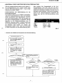
DESCRIPTION
OF THE
NEW
CIRCUIT
o
Super
linear
circuit
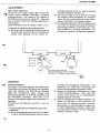
Fie.2
is the
block
diagram
of
the B-class
amplifier.
In
the B-class
amplifier,
transistors
Q3,
Q4
are
switched
ON
and
OFF
according
to the input
signal
to
apply
current
to
the load
RL.
Q3
is
ON
and
Q4
is
OFF when
the input
signal
is
positive,
and
they
operate
in reverse
when
the input
signal is
negative.
Idle
current
is
applied
to minimize
distortin
caused
by non-linearity
at the
time
the
transistor
are
switched.
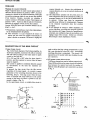
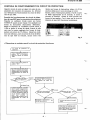
In
general,
the
bias
circuit fixes
the idle
current
regardless
of the input
signal. As
a result,
it
causes
generation
of the
switching
distortion
shown
in
the
following.
(Fig
3).
Time
lag
occurs
when
the
tran-
sistor
is
switched
ON
from
OFF
due
to the
carrier
storage
of the
base;
the
effect is
greater
as the
fre-
quency
is higher.
(Fig.
3).
In
the
super-linear
circuit, a variable
bias
circuit
is
INPUT
EINGANG
ENTREE
Fig.
2
Abb.
2
used to
adjust
the bias voltage
automatically
so
that
Q4
is
not
switched
off
when
Q3
is
ON. Accordingly
switching
distortion is
minimized.
This
circuit
is
in-
tegrated in
an IC
module which
also includes
the
out-
put
transistors.
o
LED
power
meter
drive
circuit
7
LEDs
per
channel
are used
to indicate
output
level.
These
LEDs
and driven
by meter
circuit;
the relation-
ship between
the output
level
and
the number
of
LEDs
lit when
8O
speakers
are
connected is
as shown
in Fig. 4.
Fig.
3
abb.
3
1234567
Time
lag
of the
output
signal
caused by
carner storage.
Zeitvedbgerung
des
Ausgangssignals
aufgru
nd
des
Entladeverzugs.
Retard
du
signal
de
sortie
provoqu6
par
le
stockage
de
porteuse
Fig.
4
Abb. 4
POWER
OUTPUT
40
10
4
2
0.2
0.04
0.005
t;
:l; :?i
t:
'.:i
ji
:i:
i] it tr
,t:
o
'.a.:
':i
t,
..*
o o
'.?,
i?j
'i'
o o
o
.:}.:i1
o o
o
o
iiiooooo
oooooo
-4:
A

HITACHI
HA.38OO
A
a
a
BESCHREIBUNG
DES NEUEN
SCHALTKREISES
o
Super-linearer Vorspannu
ngs-Schaltkreis
In Abb. 2
ist das Blockschaltbild
des Versttirkers
der
Betriebsklasse
B
dargestellt. Bei
einem
Verstlrker
der
Betriebsklasse
B werden
die
Transistor
Q3
und
Q4
in
Abhiingigkeit
von
den Eingangssignalen
in
den
leitenden
bzw.
sperrenden Zustand
versetzt,
um
den
Ausgangsstrom
zur
Last RL zu
liefern.
Bei
einem
positiven
Eingangssignal
leitet
Q3,
wogegen
Q4.sperrt;
bei einem negativen
Eingangs-
signal
gilt
der umgekehrte Zustand.
Eine Vorspannung
wird
angelegt,
um
Schaltver-
zerrungen
aufgrund von Nichtlinearititen
beim
Schalten
der
Transistoren
zu
vermeiden.
Normaler-
weise
wird
diese Vorspannung
unabhiingig
vom
Ein-
gangssignal
konstant
gehalten,
so
da8
die
nachfolgend
gezeigten
Schaltverzerrungen
verursacht
werden
(Abb.
3). Aufgrund
des Entladeverzugs
der
Bosis kommt
es
zu
einer Zeitverzdgerung,
wenn
der
Transistor vom
sperrenden in
den leitenden
Zustand
umgeschaltet
wird;
diese Auswirkung
nimmt
mit
steigender
Frequenz
zu
(Abb.
3).
In
dem
super-linearen
Schaltkreis wird
ein
Schaltung
RENSEIGNEMENTS
CONCERNANT
LE
o
Circuit
super lin6aire
mit
verinderlicher Vorspannung verwendet,
die die
Vorspannung
automatisch so einstellt,
daB der Tran-
sistor
Q4
bei
leitendem
Transistor
Q3
ebenfalls im
leitenden
Zustand verbleibt.
Dadurch
werden
natiirlich
die Schaltverzerrungen
auf
ein
Minimum
begrenzt. Diese
Schaltung ist in
einem
IC-Modul
in-
tegriert,
der auch die
Ausgangstransistoren
enthilt.
o
Treiberschaltkreis
ftir LED-Leistungsmesser
Fiir
die Anzeige des ausgangspegels
werden 7
Leucht-
dioden
(LED) pro
Kanal verwendet.
Diese
Leucht-
dioden werden tiber den Instrumenten-Schaltkreis
angetrieben.
Der Zusammenhang
zwischen
der Aus-
gangsleistung
und der Anzahl
der aufleuchtenden
LEDs bei Verwendung von Lautsprecherboxen
mit
einer Impedanz von 8 Ohm ist in Abb. 4
dargestellt.
NOUVEAU
CIRCUIT
tion
variable
est employ6
pur
ajuster automatique-
ment
la tension
de
polarisation
pour que
le
transistor
Q4
ne soit
pas
commut6 sur
arr€t
lorsque
le
transistor
Q3
est commut6
sur
marche.
Ceci
permet
de r6duire
les
distorsions de
commutation. Ce
circuit
est int6gr6
dans un module
d circuit
int6gr6
qui
incorpore
€,gale-
ment des transistors
de sortie.
o
Circuit de
commande d'indicateur
i diodes
6lectroluminiscentes
7
diodes 6lectroluminiscentes
par
canal sont
utilis6es
pour
indiquer
le niveau
de sortie.
Ces diodes
sont
mises
en fonction
par
le
circuit d'indicateur,
le rap-
port
entre
le
niveau de
sortie et le nombre
de
diodes
allum6es
quand
des hautparleurs
d'une imp6dance
de
8
ohms
sont raccord6s,
est indiqu6
sur la figure
4Par
ailleurs.
La Fig. 2
est le
sch6ma
synoptique
de I'amplificateur
de classe B. A
I'int6rieur
de I'amplificateur
de
classe
B, les
transistors
Q3
et
Q4
sont
commut6s
sur marche
et arr€t
en
fonction
du signal
d'entr6e
qui
est appli-
qu6 pour
que
le
courant soit
appliquE
d
la
charge
RL.
Le transistor
Q3
est mis
en
fonction,
Q4
est
mis
au
repos
lorsque
le
signal d'entr6e
est
positif;
ils
fonc-
tionnent
d I'inverse
lorsque
le
signal
d'entr6e
est
n6gatif.
Un
courant
d6watt6
est appliqu6
pour
r6duire
les
distorsions
provoqu6es
par
le manque
de
lin6arit6
au
moment
oti
les
transistors
sont
commut€s.
En
rdgle
g6n6rale,
le
circuit
de
polarisation
fixe
le
courant
dEwatt€
quelle
que
soit
la
valeur
du signal
d'entr6e.
Il
en
r6sulte
que
ceci
provoque
des
distorsions
de
commutation
repr6sent6es
comme suit.
(Fig.
3)
Un
retard
se
produit
lorsque
le
transistor
est
commut6
sur marche
de sa
position
d'arr6t
suite au
stockage
de
porteuse
d sa
base;
plus
la fr6quence
est
6lev6e
et
plus
I'effet
est important.
(Fie.
3).
Dans
le
circuit
Super Lin6aire,
un
circuit
d
polarisa-
a
5

HITACHI
HA-3800
CHECKING
THE
OPERATION
OF
THE
PROTECTION
CIRCUIT
When
the
output circuit
is repaired by
replacing
the
power
transistors,
etc.,
perform
and
operation check on
the
ASO
(Area
of Safe Operation)
detection circuit.
Operation check
of the
ASO
detection circuit
for
the output transistors
Connect the audio oscillator to
the
TUNER IN ter-
minals with
the speaker terminals
unloaded
(speaker:
disconnect). Set the
frequency
of
the audio oscillator
at
I kHz
and adjust the
level
of
the
input
signal
so that the
voltage at
the speaker
terminals
is approx. 5V
rms.
Under these conditions, short-circuit
the speaker
ter-
minals of the channel
to which thb
input signal
is ap-
plied
using
a
lead wire, etc.
If
this
short-circuit
makes
the
ASO
detection
circuit
operate,
no output appears
at
the speaker
terminals
even
if
the
lead wire used
for
short-circuiting
is
removed.
Next,
turn
off the
power
switch and, after approx.
l0
sec.,
turn
the
power
switch on
again. When
output
comes out
of the
speaker terminals,
this indicates
that
the
ASO
detection
circuit
is
operating
normally.
Fig.
5
\2
v
o
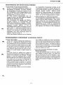
Phenomena
and remedies when the
protection
circuit operates
Protection
circuit operates
Set the
power
switch
to
OFF
and Volume Control
MlN.
Turn
the
power
switch ON
After 6-10 seconds,
play
a
record
or
receive a broadcast,
and
gradually
raise volume.
the speaker sound
disappear?
Volume Control
MIN and
the
power
switch to OFF.
re the speaker
cords
shorted
ls
the
speaker
impedance
correct?
Amp. is normal.
When
the
unit
operates
without
the
speaker
cord
shorted, the
ASO detec-
tion circuit
is
operation.
Use
the
unit with Volume Control
a
little
power.
Use speakers with impedance
of 8
-
16
ohms
when
using
2
sets
of
loudspeaker
systems
simultaneously.
6
v

HITACHI HA-3800
KONTROLLE
DER
FUNKTION
DER
SCHUTZSCHALTING
Falls die
Ausgangsschaltung
repariert
wurde,
indem z.b.
.v\
die
Leistungstransistoren
usw. erneuert
wurden,
dann
muB
die
ASO-Schutzschaltung
(ASO
=
Area
of Safe
Operation)
kontroliert werden.
Funktionspriifung der
ASO-Schaltung fUr
die
Leistu n
gstra
nsisto
re n
Den Frequenzoszillator an die
TUNER IN
anschlieBen,
wobei die Lautsprecherklemmen
keine Last
aufweisen
diirfen
(Lautsprecher
nicht angeschlossen).
Die
Fre-
quenz
des
Frequenzoszillators auf
I kHz
einstellen
und
den
Pegel des
Eingangssignales so abgleichen, daB
die
Spannung an den
Lautsprecherklemmen etwa 5V
(Mittelwert,
bewertet)
betriigt.
In diesem Zustand
sind
die Lautsprecherklemmen
kurzzuschlieBen,
und
zwar
die
Klemmen
jenes
Kanals, an welchen
das
Eingangssignal
angelet
wurde.
Falls dieser Kuzschlu8
zu
einem
Ansprechen
der
ASO-Schutzschaltung
fthrt,
/^
.^
dann erscheint
kein
Ausgangssignal an den
Laut-
sprecherklemmen,
auch
nicht
wenn den zum Kurz-
schlieBen
der
Klemmen verwendete
Draht entfernt wird.
Danach den
Netzschalter abschalten
und
nach
etwa
l0
Sekunden
wieder einschalten.
Wenn nun ein Ausgangs-
signal an
den
Lautsprecherklemmen
festgestellt
rvird
bedeutet dies,
daB die
ASO-Schutzschaltung richtig
aubeitet.
o
Ursache
und
Abhilfe
bei Ansprechen der
Schutzschaltung
Abb.
5
Schutzschaltung
spricht an.
Den Netzschalter abschalten
und den Lautstdrkeregler auf
Minimum stellen.
Nach 6
-
10
Sekunden eine
Schallplatte abspielen
oder
ein
R u
ndfu nkprogra mm empfangen
und langsam die
Lautstbrke
erhbhen.
Verstummen die Lautsprecher?
Lautstbrkeregler auf Minimum
stellen und Netzschalter ab-
schalten.
mpedanz der Lau
dem vorgeschriebenen
Sind die
Lautsprecherkabel
kurzgeschlossen ?
Der Verstbrker befindet
sich
in
gutem
Zustand. Wenn die
Laut-
sprecherkabel
nicht kurzge-
schaltet sind, arbeitet der
ASO-
Schaltkreis.
Das
Gerbt
bei
et-
was zugedrehtem
Lautstbrke-
regler verwenden.
Kurzgeschlossen
I
Falsche lmpedanz.
Die
Lautsprecherkabel richtig
anschlieBen.
Stbrung im Verstdrker
Wenn zwei Lautsprecherpaare
gleichzeitig
betrieben werden,
muB die lmpedanz
jeder
Box
zwischen 8 und 16
Ohm liegen.
Lautsprecher
ummen.
Richtige
lmpedanz.
.^
7

HITACHI HA.38OO
CONTROLE
DE FONCTIONNEMENT
DU
CIRCUIT
DE
PROTECTION
Quand
le
circuit de
sortie est r6par6 d la suite du rem-
placement
des
transistors de
puissance,
etc, effectuer
une v€rification
de
fonctionnement
du
circuit
de d6tec-
tion de type ASO.
Contr6le de. fonctionnement du circuit de d6tec-
tion
de
type
ASO
pour
les
transistors
de
puissance
Brancher
un oscillateur d'onde sonore aux bornes
TUNER
IN
quand
aucune
charge
n'est
appliquEe aux
bornes de haut-parleur
(haut-parleur
d6branch6).
R6gler la
fr6quence de I'oscillateur d'onde sonore d
I kHz
et ajuster le niveau du
signal
d'entr6e
de
telle
sorte.que la
tension appliqu6e
aux bornes de
haut-
parleur
soit environ de 5V
efficace.
Quand
ces condi-
tions sont
obtenues, court-circuit
met le circuit de d6tec-
tion
de
type ASO en fonction, aucune sortie
n'est
relev6e
aux
bornes
de
haut-parleur m€me
si le fil de
jonction
utilis6
pour
le
court-circuitage est
retir6.
Ensuite,
mettre
I'interrupteur
g6n6ral
d I'arr€t et aprds
un
d6lais
approximatif
de
l0
secondes, le mettre
e
nouveau
en fonction.
Quand
la
sortie
parvient
aux
bornes de haut-parleur,
c'est
le
signe
que
le
circuit de
d6tection
de
type ASO fonctionne normalement.
We
v
v
o
Ph6nomdne
et
remddes
quand
le
circuit
de
protection
fonctionne
Voltmetre
a Couurant
Osctllo$ope
alternattf
Fig.
5
Placer l'interrupteur
96n6ral
en
position
"OFF"
et le
potentio-
mdtre
de volume en
position
,,MIN.
Ne disparait
pas.
Placer
l'interrupteur
g6n6ral
en
position
"ON".
6 a
10
seconds
plus
tard, lire
un
disque ou
recevoir une bmission
radiophonique
puis
augmenter
progressivement
le
niveau
de
sortie.
son d6livr6
par
les
-parleurs
disparait-
il?
Le
potentiomdtre
de
volume
est
en
position
"MlN"
et
l'interrup-
teur
g6n6ral
est
plac6
sur
,,OFF".
'imp6dance
de haut-
convient-elle?
Les fils de
haut-parleurs
'sont-ils
court-circuit6s?
L'ampli
fonctionne normale-
ment.
Ouand l'appareil
fonc-
tionne sans
que
les fils de haut-
parleurs
soient
court-circuit6s,
le circuit
de d6tection
ASO est
mis en
fonction. Utiliser
l'ap-
pareil
pour
contrOler
un
minimum
de
puissance
avec
le
potentiomdtre
de niveau
de
sortie.
ourt-circuit6s. YElle
est correcte.
Rebrancher correctement
files de haut-parleurs.
Utiliser
des haut-parleurs
ayant
une imp6dance
de 8 i
16
ohms
quand
deux
paires
d'enceintes
sont
utilis6es en
paralldle.
Disparait
court-circuit6.
I
\z

HITACHI HA.38OO
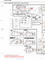
CIRCUIT
DIAGRAM
.
SCHALTPLAN.
PLAN
DE
CIRCUIT
c40t L
3.3 / 50
PHONO
(L)
(L)
TUNER
(R)
(L)
AUX
(R)
(L)
REC
(R)
(L)
PLAY
PL4OI
-PL
,^\
/^
r^
,^
ti""1l
zDe20
RO 8,2EN3
I
ol
l
ro
rl*
_sl
ON
5e
Reot
I
lO
(fu6a
ACr
*
*
*
Axial
lead
cylindrical
ceramic capacitor
Zylindrischer
Keramikkondensator
mit
axialer
suleitung
Condensateur
c6ramique
cylindrique
d conilucteur
axial
-?",3
-O'8
4lmv 22.3
Rcn
(Same
as
Lch)
? lsoP
*.o.. J o
trl se
R4|L
330
R4ilR
330
Rch
(Same
as
Lch)
R412R
330
c7t6 t/too
3.!,
llr'z'sA I i
t-2,5-6
24Ov
?-3,6-7 22OV
3-4,7-E t?OV
/^
6OHz
9

+
Bo VB
Vref.MAx VB
LED
POWER
METER UNIT
LIN GND RIN
o
Ol
(ov
Fo
(lN
(,
6
o
o
E
G
o
G
o
E,
?3i,2'
fui
EI DR
R74tL
R?43L
39K
toK
c75OL
47/16
J
Xo
iN
EO
lCTOlt
srK-ezso
31'4
c706L C7071
LTOIL
2,5
)rl1
R7O7L
R7O8L
R7O6L
6.eK
c703
L
2?/
t6
*Hi
o
J
6
o
t-
0
9
N
J6
PJ
i!9
J^
o$
tso
On
2,7K(tWt
Y
9
J
o
N
-
F
Y
o
N
o
J
N
N
N
(l
J
@
o
f-
o
J
m
N
t-
t
Tempero-
fu re
Detec t.
i?,i4"",",o.,
."€891
-
Vcc
+Vcc
MUTE
aso
rN
Rch
GND
(Same
a6
Lc h)
our
-B
GND
5 0804 ts2473
R8r4 6ak RAr5 t2K
|@
i<
rO
n
o
Retz R8
t3
-PL4O4
SVlOOmA
PL4O4
TAPE
E?
o
PL4o3
AUX
PL4OI
PHONO
o7()l
!.R
2SCr740L N
GI702
L.R
25C2259
o703L.R
2SB7 r 6
o704
L.
R
2SB7r5
Gl7()5 L.R
2S0756
o706t.R
2Sc2389
o7(,8
t.R
2SC2389
GI820
2
SD330AL
R742L
2.2K
Q8()r
2sBDFAL
o8()2
2SB514AL
oEo3
2SArOr5
Q9()l
2 SA r038
R820
330
(t/2Wl
\2
\z
\2.
Y.
J9
sl\
NN
ON
D952 L
IK34A
c95r L
t/50
R95I L
il(
I
tc90r
HAt2002
@
The circuit rymbol
ll I
means
a
fuss resistor. Whon replacing it with new one, rofor
to the CAUTION on
page
10.
Da6 Schalt.ymbol
{
-
)
.toht
f0r
Schmolzwiderstand.
B.im Austausch bitte S€it€ 10
ZUR BEACHTUNG nachlesen.
Lo symbole de circuit
{
+,
signifie
qu'il
s'agit
d'uno r6$istanc€ a tusible. Consultor
les instructions
"ATTENTION"
de la
pago
10
pout
eff€ctuer son r€mplac€ment.
E
td
Y
ld
L
a
c)
(r
ul
Y
U
0_
a
a
t!
z
I
(L
L.R-R756LR
v,

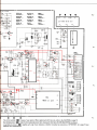
PRINTED
WIRING
BOARD. PRINTPLATTEN
.
:
-B,
:
Earth,
*:
Axial
lead
cylindrical
ceramic
capacitor
*
: zylindrischer
Keramikkondensator
mit
axialer
suleitung
*:
condensateur
c6ramique
cylindrique
dr
conducteur
axial
PLAN
DE BASE
:
Other
l
7
LOUONESS
SUBSONIC FIL.

HITACHI
HA-3800
CAUTION: Fuse
resistors are used
to improve satety
(to
protect
the circuitl. When replacing
them
with
new ohes, be sure ro use
the designatod
type. Always
use the designated fuse
without fail.
ZURBEACHTUNG:
Schmelzwiderstiinde
sind zur Erhiirung
der
Sicherheit vorgesehen
(zum
Schutz der Schaltungl. BeiAustausch
bitte nurdie
vorgeschri€bene Type
benutz€n. Vergewissern
Sie sich,
daB die
richtige Type
gewahft
ist.
ATTENTION:
L6s resistance a fusible
sont fahes
pour
afteliorer la
s6curit6 de l.appareil
{protection
de circuit).
pour
les remplacer, utiliser
le
meme
type. Utiliser toujours le
modale de tusible specifie
pour
effectuer le remplacement.
M5214t
IS2473
1S20764
RD24EB1
RD4.7EN3
RD8.2EN
ft
i-t+;
n+{T
sTK8250
IK34A
=G
-{^
25C17401N
2S8715
2SD756
2SC2389
2SAi038
25At015
s5vB20
W
25C2259
W
ERB12-01
=&
;-N
^
2SD330AL
25B5I4AL
N
h['
RAlt
.--41/\.!%'?
T
{rt
-ii'
rL
.'.
.a
4
$
s
1t
=l,l
6
qi
io
x ml-.
)
POWER
LEVEL
I\4ETER
BALANCE
TREBLE
BASS SPEAKER SW.
\

6
HTTAEHI
.HA.38OO
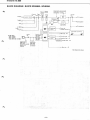
B'LOCKT DIAG
RAM' BLOCK.SGHEU}A''SCHEMA
Volume
control
Function
Tape
-,
sw.
monitor sw.
PHONO
TUNER
AUX
;_
REC
TAPE
Lplay
ACl20V
60Hz
-220v
50/60H2
-240V
50/60H2
-
120v / 220v /
240V 50/ 6OHz
Power
sw:
Tone control
Power ind.
Program
Source
ind.
Marn amp.
*Br
L
Equahzer amp.
*B
Equalizer
Amp.
-B
Main
amp.
-Bz
q
4
q
UNSWITCHED
IOOW MAX
(for
U.S.A., Canada,
Asia &
Latin
AnrerOa)
SWITCHED
IOOW
MAX
(for
U.S.A.
& Canada)
One channel
only
shown.
T
-il-

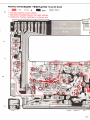
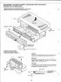
DISASSEM
BLY AND REPLACEMENT
.
ZERLEG
DEMONTAGE ET REMONTAGE
.
Removing
the cover, escutcheon
& bottom
plate
o
Ausbau der Abdeckung, der Schildanbringung
und der
Bodenplatte
o
D6poser le
couvercle,
le cache-entr6e
et
la
plaque
inf6rieure
Vz
\l
U.
3
r'x
lO bind iopping
(x4)
3tx
6DT
o
Removing
the
power
transistor
o
Ausbau
der
Leistungstransistoren
o
D6poser les
transistors
de
puissance
3/x6DT
bind
(x4)
-.4
a
4Px IODT
bind
(x4)
l""ur"n"on
oss'y
\2.
Shildonbringung
Coche
-
entr6e
3PxlObind
topping (x
2)
€
PUSH
The
switch may be damaged
when the
knob is
pulled
with the
switch
locked. Be
sure to
release locking
before
pulling
out
the
knob.
Der
Schalter
kbnnte
beschiidigt
werden,
wenn der
Knopf bei ver-
riegeltem
Schalter
gezogen
wird.
Unbedingt
die
Verriegelung
freigeben, bevor
am
Knopf
gezogen
wird.
Le commutateur risque d'6tre endommag6
si
le bouton est tirA
lorsque
le commutateur
est en
position
verrouill6e.
Ne
pas
oublier
de
lib6rer le
verrouillage
avant de vouloir
retirer le bouton.
,f
3Fxl6
Power
tronsistor
Leislungslronsis'
Tronsistors
de
puissonce
bind
lopping
(xZl
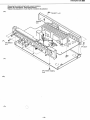
ZERLEGU
NG
UND AUSTAUSCH
PUSH SWITCH
-12-
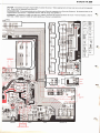
P.W.
B.
/rorue,
suBSoNlc-FlL.\
I LOUDNESS
SW.
I
\sprRren sw.
/
v

HITACHI HA-38fl)
F\
,7\
A
o
Removing the
printed
wiring
boards,
power
transistors
o
Ausbau der Leitterplatten,
Leistungstransistoren
o
D6poser des
plaquettes
a circuit
imprimd,
transistors de
puissance
3lx6DT
(x2)
&sprSDT (
x4)
3Px20bind
(x
5)
A
3r'
x
lObind
topping
(x4)
-
t3
-

HITACHI HA.38OO
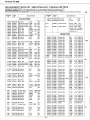
REPLACEMENT PARTS
LIST. ERSATZTEILLISTE
.
TABLEAU DES
PIECE
BEPRODUCT SAFETY NOTE: Components marked with a
A
have special charactoristics
important to safety,
SICHERHEITSHINWEIS:
Die
mit
lL
gekennzeichneten
Komponenten
haben
wichtig€ Sicherheitsautgaben.
NOTICE DE SECU RITE DE FABRICATION: Les composants
qui
sont accompagnes du symbole
A
possAdemt
des caract6ristiques speciales,
-,!i
SYMBOL
No.
PART
No.
DESCRIPTION
CAPACITORS
c40lLR
c402LR
c403LR
c404LR
c405LR
C406LR
c407LR
c408LR
C4O9LR
c4lOLR
c4ll
c4t2
c60lLR
c602LR
c603LR
c70lLR
c702LR
c703LR
c704LR
c705LR
c706LR
c707LR
c708LR
c7lOLR
cTllLR
C7IZLR
C7I3LR
c7l5LR
c7t6
c74lLR
c742LR
c743LR
c745LR
c746LR
c748LR
c749
c750LR
c80l
c802
c803
c804
c805
c806
c807
c809
c8l0
c90t
c902
c903
c905
c906
0252813K
0230036
023N24
023m,24
0252232K
0275234
0275241
02528t3K
u740t5
0240020
0252621K
0252621K
0240002
02750t4
0276011
025281IK
0230036
0252522K
024N06
024N06
o230032
023m32
02760t1
0275015
0240N6
024W06
0274015
0252522K
025301 lK
02s2s22K
0274011
0252521K
0257t8t
02760t3
0nffit2
02750t3
0252525K
0245408
0245408
02s99
3 I
02s9931
02s262tK
025262tK
0252533K
025263tK
02Mt7t
02s223tK
02525ztK
02528tlK
0252625K
02525ztK
Electrolytic
Cylindrical ceramic
Cylindrical ceramic
Cylindrical ceramic
Electrolytic
Mylar, film
Mylar, film
Electrolytic
Mylar, film
Cylindrical ceramic
Electrolytic
Electrolytic
Cylindrical ceramic
Mylar, film
Mylar, film
Electrolytic
Cylindrical ceramic
Electrolytic
Cylindrical ceramic
Cylindrical ceramic
Cylindrical ceramic
Cylindrical ceramic
Mylar, film
Mylar, film
Cylindrical ceramic
Cylindrical ceramic
Mylar, film
Electrolytic
Electrolytic
Electrolytic
Mylar, film
Electrolytic
Electrolytic
Mylar,
film
Mylar, film
Mylar, film
Electrolytic
Ceramic discal
Ceramic discal
Electrolytic
Electrolytic
Electrolytic
Electrolytic
Electrolytic
Electrolytic
Ceramic discal
Electrolytic
Electrolytic
Electrolytic
Electrolytic
Electrolytic
3.3pF
l00pF +Stlo
l0pF +50/o
l0pF +5s/o
220p,F
,0.039pF
+590
0.0l3pF +590
3.3pF
4700pF
+1090
l00OpF
los.F
lOpF
l50pF +1090
0.033pF + l09o
0.lpF +1090
lpF
l00pF +Stlo
22pF
330pF +1090
330pF +1090
43pF
+5t/o
43pF +5s/o
0.lpF +1090
0.047pF
+l0t/o
330pF
+1090
330pF
+100/o
4700pF +1090
22y.F
lpF
22pF
l000pF +1090
lOpF
lpF
0.22p,F + l09o
0.l5pF
+l0o/o
0.022pF
+ l09o
47
p"F
0.0lpF +20t/o
0.0lpF +20s/o
6800pF
6800pF
lOpF
lOpF
330pF
100pF
0.0lpF
47
y.F
lOpF
lpF
47
p,F
los.F
!l$t/o
50v
50v
50v
50v
6.3V
50v
50v
50v
50v
50v
25V
25V
50v
50v
50v
50v
50v
l6v
50v
50v
50v
50v
50v
50v
50v
50v
50v
l6v
l00v
l6v
50v
l6v
50v
50v
50v
50v
l6v
500v
50v
50v
50v
25V
25V
l6v
25V
50v
6.3V
l6v
50v
25V
l6v
SYMBOL
No.
PART
No.
DESCRIPTION
A\
c95lLR
c952LR
acl
acl
02528ttK
0252805K
0243899
0243901
Electrolytic
Electrolytic
Ceramic discal
Ceramic
discal
rpF
I
sov
o.47uF lsov
,I
0.0lpF
*to$90
l25V
(for
U.S.A & Canada)
0.0lpF
'to$90
400V
(except
U.S.A., Canada,
Asia & Latin American
countries, etc.)
RESISTORS
R4OILR
R4O2LR
R,f03LR
R4O4LR
R4O5LR
R4O6LR
R4O7LR
R4O8LR
R4O9LR
R4IOLR
R4IILR
R4I2LR
A
R4I3
AR4I4
R@ILR
R602LR
R6O3LR
RTOILR
R7O3LR
R704LR
R7O5LR
R706LR
R7O7LR
R7O8LR
A
R7O9LR
RTIOLR
RTIILR
R7I2LR
R7I3LR
R7I4LR
R7I5LR
R7I6LR
R7I8LR
R72OLR
R72ILR
R722LR
R723LR
R724LR
R725LR
R74ILR
R742LR
R743LR
R744LR
R745LR
R746LR
R747LR
0t29547
0t29&7
0t29563
0129s79
0129653
0t29619
0t2956t
0t29605
0129il7
0129573
0129573
0129573
0l
10621
0l
10621
012962t
0129643
0129637
0129601
0t29661
0129583
0129583
0t2962t
0129607
0t2966t
0l 10623
0129623
0t2956t
0t2956t
0129621
0149551
0129583
012960s
0129607
01296t7
0129623
0t29683
0129653
0t34289
0l
19135
0t29645
0t29609
0t2963r
0129579
0l296tt
0t29663
0129567
Carbon film
Carbon film
Carbon
film
Carbon
film
Composition
Metal
Carbon
film
Carbon film
Carbon
film
Carbon film
Carbon film
Carbon
film
Carbon film
Carbon film
Carbon film
Carbon
film
Carbon
film
Carbon
film
Carbon film
Carbon
film
Carbon
film
Carbon
film
Carbon film
Carbon film
Carbon
film
Carbon film
Metal
(fuse
resistor)
Metal
(fuse
resistor)
Carbon film
Carbon
film
Carbon
film
Carbon
film
Carbon
film
Carbon
film
Carbon film
Carbon film
Carbon
film
Carbon
film
Metal
(fuse
resistor)
Carbon film
Carbon
film
Carbon film
Carbon
film
Cement
Carbon
film
Carbon film
47Q +5s/o
47kQ +590
l2OA +50/o
5600
+Sslo
82k0 +50/o
5.6kO
+5r/o
l00O +Ss/o
l.5kO +5t/o
47kA +590
3300
+590
3300 +5t/o
3300
+590
l00O +59/o
l00O +5s/o
6.8kO
+5t/o
33kO
+St/o
lSkO +Ss/o
lk0 +5t/o
100k0 +5t/o
8200 +5s/o
8200
+5s/o
6.8kO
+590
l.8kO +5s/o
100k0
+50/o
l50O
+Sslo
8.2kO
+50/o
l00O
+5s/o
l00O +590
6.8kO +5u/o
0.220, + l09o
8200
+Sslo
l.5kO +5u/o
l.8kO +5s/o
4.7kQ +50/o
8.2k0 +Sulo
820kO
+5s/o
82kO
+5u/o
l0O +1090
2.20 + l09o
39kO +50/o
2.2k0 +50/o
l0k0
+Ss/o
5600
+St/o
2.7kO +5s/o
l20kO +5o/o
l80O +54/o
SRDI/8P
SRDI/8P
SRDI/8P
SRDI/8P
SRDI/8P
SRDI/8P
SRDI/8P
SRDI/8P
SRDl/8P
SRDI/8P
SRDI/8P
SRDI/8P
RNI/4B
RNI/4B
SRDI/8P
SRDI/8P
SRDI/8P
SRDI/8P
SRDI/8P
SRDI/8P
SRDI/8P
SRDI/8P
SRDI/8P
SRDI/8P
RNI/4B
SRDI/8P
SRDI/8P
SRDI/8P
SRDI/8P
RWC3
SRDI/8P
SRDI/8P
SRDI/8P
SRDI/8P
SRDI/8P
SRDI/8P
SRDI/8P
RCI/2GF
RN2B
SRDI/8P
SRDI/8P
SRDI/8P
SRDI/8P
SRDI/8P
SRDI/8P
SRDI/8P
-\
i
I
1
l
l
l
1
}A
-14-

HITACHI
HA-3800
n\
A\
,^\
,a
SYMBOL
No.
PART
No.
DESCRIPTION
R748LR
R755LR
R756LR
A
RSOI
AR8O2
R803
R804
R805
R806
R807
R808
A R8O9
A R8IO
R8ll
R8l2
R8l3
R8l4
R8r5
R8l6
R820
R90l
R902
Re03
R904
R905
R906
R9ll
R9l2
R95ILR
R952LR
R953LR
R954LR
0r29639
0129673
0t2960t
0t2966t
0t29635
0t29577
ot29647
0l
13821
0l
13821
0129581
0t2965t
0129633
0129651
0t29633
0l
19543
0t34367
012966t
0tt9M6
0r2964t
0129639
0t29639
0t29631
6800
6800
8200
Carbon
film
Composition
Composition
Composition
Carbon
film
Metal
oxide
Carbon
film
Carbon
film
Carbon film
Carbon film
Carbon film
Carbon
film
Carbon film
Carbon
film
Carbon film
Carbon film
ffitffi;
3300
+ l09olRcl22cF
l00k0
+5t/o
2.7k4
+ l09o
27kA
+5Vo
22kA
+50/o
22kA
+50/o
l0k0
+50/o
SRDI/8P
RSIB
SRDI/8P
SRDI/8P
SRDI/8P
SRDI/8P
22kQ
+5Vo
330kO
+5s/o
lkO
+5t/o
l00k0
+50/o
l5k0
+590
470Q
+50/o
I
Cs
&
TRANSISTORS
IC4OILR
ICTOILR
rc90l
Q70lLR
Q702LR
Q703LR
Q704LR
Q705LR
Q706LR
Q708LR
Q80l
Q802
Q803
Q820
Q90l
2367922
2368941
2367372
2328653
2367654
2328862
2328862
2328872
2328783
2328783
2328972
2328962
2329183
2328972
2328772
M52t4L
STK825O
HAl2002W
2SCI740LN
@
2SC225e
@
258716
@
2sB716
@
2SD756
@
2sc238e
@
25C2389
@
2SD330AL
@
2SB5I4AL
@
2SAl0l5
@
2SD330AL
@
2SAl038
o
DI
ODES
&
THERMISTER
DTOILR
D702LR
233760t
233760t
1s2473
ts2473
SYMBOL
No.
PART
No.
DESCRIPTION
D7O5LR
D706LR
D80l
D802
D803
D804
D95ILR
D952LR
zD80t
2D802
ZD8O3
2D820
ZD95ILR
THTOILR
2337ffiI
2336t5t
2337341
2337762
2337762
2337ffit
2337922
2337922
2338647
23386/.7
233859s
2338613
2338589
23471t4
ts2473
ls2076A
55VB2O
ERBI2-01
ERBI2-01
rs2473
IK34A
IK34A
RD24EBI
RD24EBI
RD4.7EN3
RD8.2EN3
RD3.9EN2
Thermister
VARIABLE RESISTORS
R65l
R652
R76ILR
R762
R763
0151846
0151857
0150958
0151807
0151807
200ko
-
(w)
(BALANCE)
200ko
-
(B) (voLUME)
20kO
-
(B) (for
idle
current
adj.)
20ko
-
(c) (BASS)
20ko
-
(c) (TREBLE)
corLs
LTOILR
22273rr
Audio
trap
coil
-
2.5p,H
MISCELLANEOUS
s40l
-404
s601,602
s70l
s901,902
s901,902
A
CPI
A
fo
Fuse
-
2.5A
(for
U.S.A.
& Canada)
Fuse
-
Tl.25A
(except
U.S.A.,
Canada,
Asia
& Latin American
countries,
etc.)
Power
switch
(for
U.S.A.
& Canada)
Power
switch
(except
U.S.A.
& Canada)
Push
switch
Push
switch
Push
switch
Push
switch
(except
U.S.A.
& Canada)
Push
switch
(for
U.S.A.
& Canada)
Spark killer
(for
Asia
& Latin
American
countries)
AC
outlet
4P
US
pin
jack
6P US
pin
jack
Headphone
jack
Speaker terminal
(8P)
Meter lamp
8V, 0.lA
(Y)
Meter lamp
8V, 0.lA
(C)
7P
miniature
connector
36 x 6 DT
bind screw
3d x l0
bind tapping
screw
36 x 16
bifrd
tapping
screw
r FINAL
ASSEMBLY
Escutcheon
ass'y
Knob
ass'y
(VOLUME)
Knob
(BASS,
TREBLE,
BALANCE)
Cover
3d
x
l0
bind tapping
screw
36
x 6
DT
bind screw
46
x
l0
DT
bind
screw
^\
a
-
t5
-

HITACHI
HA.38OO
for DIAL MECHANISM ASSEMBLY
Sub
panel
ass'y
F
push
spring
Knob ass'y
(PHONO)
Knob
ass'y
(TUNER)
Knob
ass'y
(AUX)
Knob ass'y
(TAPE)
Leg
Knob
(POWER)
Knob
(SPEAKERS,
TONE,
Others)
Power
transformer
(for
U.S.A. & Canada)
Power
transformer
(except
U.S.A., Canada &
Australia)
Power
transformer
(for
Australia)
LED meter unit
Lamp with lead
wire
4d
x 8
DT
bind
screw
3d x
l0
DT bind screw
3Q x
12 DT
bind screw
36 x 6 DT bind screw
3d
x
l0 bind
tapping
screw
3d x 8 DT bind screw
3d
x
l0
bind
flat llead screw
(for
U.S.A. & Canada)
36
x
?.0 DT
bind
screw
4@7842
u29851
3290.54t
3290542
3290543
3290s4./.
39284tt
393229r
394296t
224753t
2U7532
2247533
23690rr
2767628
4567422
45674t3
4567454
45674tt
4784t06
4s67432
458t982
4567417
a
-
SYMBOL
No.
PART
No.
DESCRIPTION
A
A
A
A
A
A
A
A
A
A
for R
26s'Ril I
2727ts31
EAR PLATE
ASSEMBLY
Bushing
(for
U.S.A.
&
Canada)
Bushing
(except
U.S.A. & Canada)
Power
supply cord
(for
U.S.A. & Canada)
Power supply cord
(except
U.S.A., Canada, U.K. & Australia)
Power supply cord
(for
U.K.)
Power supply cord
(for
Australia)
Voltage
selector
switch
(for
Asia
&
Latin American
countries, etc.)
Fuse
holder
(for
Asia &
Latin American
countries,
etc.)
Fuse-Tl.25A
(for
Aisa & Latin American
countries, etc.)
AC
outlet
(for
Asia & Latin American
countries, etc.)
3d
x
8 DT bind screw
for AGCESSORIES
E
socket adaptor
(for
Asia
&
Latin American
countries, etc.)
Fuse-T2.5A 250V
(for
Asia
& Latin American countries,
etc.)
-
t6
-
^

HITACHI
HA-3800
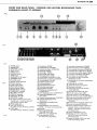
FRONT AND REAR PANEL
.
VORDERE
UND
HINTERE
BEDIENUNGS
TAFEL
PANNEAUX
AVANT ET ARRIERE
A
^\
O
POWER
switch
@
enorues
pct
@
SPenfeRS switches
@
anss control
@
fneale
controt
€)
BALANCE
controt
O
fOrue
switch
@
suesoNtc-FtLTER
switch
@
louolrtESS
switch
@
VOLUME
control
@
Program
source indicators
@
Function
selectors
@
fnee
monitor switch
@
Power
level indicators
@
Ground terminal
(GND)
@
enOruO INPUT
terminats
@)
TUNER INPUT
terminals
@
nUX INPUT
terminals
@
fnee
REC
terminats
@
fnee
PLAY terminats
@)
SPEAKERS
terminats
@
nC
outlet
(3
outlet
for
U.S.A. and
Canadian sets, 1
outlet
for
Asian and
Latin America
countries
sets.)
@
Power
supply
cord
@
volrncE
sELEcroR
(for
Asian
and Latin American
countries)
@
FUSE
hotder
(for
Asian
and Latin American
countries)
@
Netzschalter
(POWER)
@
Kopfhbrerstecker
(
PHONES)
@
Lautsprecherschalter
(SPEAKERS)
@
Tiefenregler
(BASS)
@
Hbhenregler
(TREBLE)
@
Balanceregler
(
BALANCE)
@
Klangregelschalter
(TONE)
@
I nfraschallfilter
(
SU
BSON lC-Fl
LTER)
@
Gehbrrichtige
Lautsterke
(
LOUDNESS)
@
Lautstdrkeregler
(VOLUME)
@
Programmquellenanzeige
@
Funktionswahltasten
@
Bandmithbrschalter
(TAPE)
@
S
pitzenleistu
ngsa nzeigen
@
Erdungsklemme
(GND)
@
Plattenspieler-
Ein
gangsbuchsen
(PHONO
INPUT)
@
Tuner-Eingangsbuchsen
(TUNER
INPUT)
@
Zusdtzliche
Eingangsbuchsen
(AUX
INPUT)
@
Tonband-Aufnahmebuchsen
(TAPE
REC)
@
Tonband-Wiedergabebuchsen
(TAPE
PLAY}
@
Lautsprecher-A
nschluBklemmen
(SPEAKERS)
@
Kaltgerbtdstecker
(3
firr
USA und
Kanada,
1 fi.rr Asien
und Lateinamerika)
@
Netzkabel
@
S
pannungs-Wahlschalter
(VOLTAGE
SELECTOR)
(FUR
Asien
und Lateinamerika)
@
Sicherungschalter
(
FUSE)
(Fi.lr
Asien
und Lateinamerika)
@
lnterrupteur
d'alimentation
(
POWER)
@
Prise
de
casque d'6coute
(PHONES)
@
Commutateurs
d'enceintes
(
SPEAKERS)
@
Commande
des tonalit6s
graves
(BASS)
@
Commande des
tonalit6s aigubs
(TREBLE)
@
Commande
d'equilibrage
(BALANCE)
@
Commutateur
de
tonalit6
(TONE)
@
Commutateur
de filtre
infrasonique
(SUBSONIC-FILTER)
@
Commutateur
de
correcteur
physiologique
(LOUDNESS)
@
Commande de VOLUME
@
T6moin
de source
de
programme
@
S6lecteurs de fonction
@
commutateur de
controle de
bande
(TAPE
MONITOB)
@
lndicateurs
de
puissance
de
crOte
@
Borne de
mise d la
terre
(GND)
@
Bornes
d'entr6e PU
(PHONE
INPUT)
@
Bornes
d'entr6e de
tuner
(TUNER
INPUT)
@
Bornes d'entr6e
auxiliaire
(AUX
INPUT)
@
Bornes d'enregistrement
de bande
(TAPE
REC)
@
Bornes
de lecture de
bande
(TAPE
PLAY)
@
Bornes d'enceintes
(SPEAKERS)
@
Prise
de.courant
alternatif
(3
prises
pour
appareils vendus
aux Etats-Unis
et au
Canada, 1
prise pour
les
pays
d'Asie
et
d'Am6rique
latine)
@
Cordon d'alimentation
en C.A.
@
S6lecteur de
tension
(VOLTAGE
SELECTOR)
(pour
pays
d'Asie
et
d'Am6rique
latine)
@
Support
de fusible
(FUSE)
(pour
pays
d'Asie
et
d'Am6rique
latine)
-17-

-
-]
__l
HITACHI
SALES CORPORATION OF AMERICA
Eastern Regional Office
1200 Wall
Street
West,
Lyndhurst,
New
Jersey 07071
Tel.
201-935-8980
Mid-Western Regional
Office
1400 Morse Ave., Elk
Grove
Village, lll.
60m7
Tel. 312-593-1550
Southern
Regional
Office
510
Plaza
Drive College Park,
Georgia 30349
Tet. 444-763-0360
Western Regional
Office
4O1 West Artesia
Boulevard, Compton, California
w220
rel.
213-537-8383
HITACHI
SALES CORPORATION
OF
HAWAII.
tNc
743-G Waiakamilo Rd., Honolulu,
Hawaii
96817
Tel. 808-841{431
HITACHI
SALES CORP. OF CANADA Ltd.
3300
Trans Canada
Highway Pointe Claire,
Ouebec,HgRl Bl, Canada
Tel. 514-697-9150
HITACHI
SALES EUROPA
GmbH
2 Hamburg
V,
Kleine
BahnstraBe
8,
West
Germany
Tel. 850 6071-75
HITACHI
SALES
(U.K.}
Ltd.
Hitachi House,
Station Road, Hayes,
Middlesex
U83
4DR,
England
Tel.
01-W-8787
(Service
Centre:
01-848-3551)
HITACHI
SALES SCANDINAVIA
AB
Rissneleden
8, Sundbyberg, Box 7138,
3-172-07
Sundbyberg
7
,
Sweden
Tel. 08-98 52 80
HITACHI SALES
NORWAY A/S
Oerebekk
1620
Gressvik
P.O.
Box 46 N-1601
Fredrikstad, Norway
f el. 032-28050
SUOMEN
HITACHI
OY
Box
151,
SF-15100 Lahti
10, Finland
Tel. Lahti 4 241
HITACHI SALES A/S
Kuldyssen
13,
DK-2630 Taastrup, Denmark
Tel. 02-999200
HITACHI SALES A.G.
5600 Lenzburg, Switzerland
Tel. 064-513621
HITACHI-FRANCE
(Radio-T6l6vision
Electro-
M6nagerl
S.A.
9,
Boulevard Ney 75018, Paris, France
Tel.201-25-00
HITACHI SALES WARENHANDELS
GMBH
A-1 180/Wien, Kreuzgasse 27
Tel.
(00432221
439367
/8
HITACHI
SALES AUSTRALIA Pty Ltd.
153 Keys Road,
Moorabbin,
Victoria
3189
Australia
f el. 95-8722
HITACHI Ltd. TOKYO JAPAN
Head Office:
5-1,
1-chome, Marunouchi,
Chiyoda-
ku, Tokyo
100
Tel. Tokyo
12121
1111
Cable
Address:
"HITACHY"
TOKYO
Codes:
All
Codes
Used
^
HA-3800
TY
No.262
EGF
Printed in Japan
(H)
-
 1
1
-
 2
2
-
 3
3
-
 4
4
-
 5
5
-
 6
6
-
 7
7
-
 8
8
-
 9
9
-
 10
10
-
 11
11
-
 12
12
-
 13
13
-
 14
14
-
 15
15
-
 16
16
-
 17
17
-
 18
18
-
 19
19
-
 20
20


Hitachi HA-3800 Benutzerhandbuch
- Kategorie
- Musikinstrumentenverstärker
- Typ
- Benutzerhandbuch
in anderen Sprachen
- English: Hitachi HA-3800 User manual
- français: Hitachi HA-3800 Manuel utilisateur
