
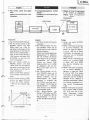
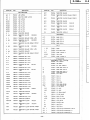
SERYICE
TUIANUA1
Englirh
This
unit
employs
the UD-l
standard
mechanism.
When
inspecting and
re'
pairing
this
unit,
read this
together
with
the
service manual
(No.
11551
of
the UD
mechanism
(UD-l).
PREGAUTION;
The following
precartions
strould bo
obsened
when relicittg.
l. Since mEny
perts
in
thc uniî
have
special safety mlabd charc-
tsristics, ahrayr u$
gcruinc
Hitrcfii's
repbccmcnt
partr.
Espccially critical
plrts
in
tho
porvcr
cimrit
block
should
not be
replad
with thoec of othof
manufactupru.
Criticd
parts
art
marked with
A
in
úre *hematic
diagram,
and circ-uit
boad
diagrun.
2.
Before retuming a roprired unit to
the customgr,
the service tedr-
nician
must thorougNtly telt tlto
unit to ascertain thEt it ir corn-
pletely
safe to operate without
danpr
of electrical
shock.
BS
AU
USA
Canada
General Area
Sritzerland
and Scandinavia
Great Britain
Australia
Dieses
Geràt
ist
mit
der
Standard-
Mechanik
UD-l
ausgerùstet.
Fùr
Prúfung und
Eeparatur
dieses
Geràtes
ist daher die
vorliegende Anleiturg
gemeinsam
mlt
der
Wartungsanleitung
{Nr.
1155)
fiir
die
UD-Mechanik
(UD-l
)
zu verwenden.
Bci
Wartungsaóeiten
dnd die
folgendcn
SicheúeitsmaBnahmon zu
bcacfitcn:
1.
Da verschiedene
Tsile diesas
Geràtes
Sicherheitsfunktionen auf
-
woison,
nur Originsl+litechi.
Ersatztoile
venvenden. Kritirdre
Teile
im Netztcil
sollton niclt
durch
àhnlidre
Teile
andsrer
Hersteller
eÉotzt wsrdcn. Alle
kritirchen
Teilc sind im
Schalt.
plan
und im Di4ranrm
dor
Scfid$lantinen
mit dcm
Symbol
I
pkennzeichnet.
2. Yor
der
Audiefcrung cines
reparierten
Geràtes
an don
Kunden
muB
der Wartungstechniker
da:
Geràt
einer
griindlichcn
Priifung
untezietran,
um sicherzustollen,
daB
sicfierer
Betrieb ohne die
Gefahr
von
elektriscfirn
Schlàgpn
gwàhrleistet
ist.
USA
Kanada
Allgemeine
Gebiete
Schweiz
urÉ
Skandinavien
GroBbritannien
Australien
Englirh
Dcutrch
Frongoir
No. 1255
Cet
appareil est
équipé du dispositif
standard
UD-l.
Au
moment
de
procéder
à une
remise en état
ou un€
inspection
de
l'appareil,
veuillez
prendre
connaissance
du texte
suivant
eî
du Manuel d'entretien
(No
11551
pour
disPositif uD
(uD-l).
de róor
Les
pdcartionr
srivnbs
doivent
Otrt obreruóer
à chaque
qu'une
róparation
doit
0tre fair.
l.
Etant donné
gue
de
nqnbreux
cdnpoc{rt3
de
l'rppareil
pocddent
der cractórifiiqucr
ro-
Irtaver à la dcuri!é, utili$r
uniquement
des
piècas
de
rchmga
d'origine
Hitadri
pour
effrcùer
un
remplcsment.
Ceci
Remaque:
u.....
Etats-Unis
C..... Canada
W
Tous
prys
FS
.
.
. .
Suisse
et
Scandinavie
BS
. . . . Grande-Bretagne
AU...
Australie
4
se rrpports notrnm€nt
arx
piAer
critiques
du blc d'alimentîion
..qui
ne doivent en
a.nun cr 0trr
remplmóes
par
celler d'r,rtlpr
fabricants.
Les
pÈrs
critiques
ront cconpagnés du rymbole
A
Cans le sdréma de montlgp
ct
3ur le shóma
de
plque
de
càblage.
2. Avant
de rEtqrmer l'appareil
répad ar
client, le
tadrnicien
doit
proóder
a
un esd conplet
pdrr
s'asqrr€r
que
l'apparcil ne
pÉsente
arcun dsrggr
de
drcs
électriquee
STEREO
GASSETTE TAPE DECK
September1979

:
...,
.
Endi$.
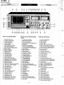
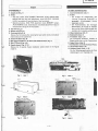
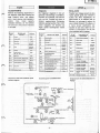
KEY
TO ILLUSTRATIONS
i
t'
I
2
3
4
5
6
7
8
I
't0
11
12
t3
't4
15
't6
17
f8
19
20
21
22
23
24
25
26
27
28
29
30
31
32
33
34
35
RECORD
INDICATOR
PLAYBACK
INDICATOR
PAUSE
INDICATOR
3-HEAD INDICATOR
TAPE
COUNTER
COUNTER
RESET BUTTON
AUTO-REWIND
SWITCH
BIAS FINE
ADJUSTMENT
KNOB
METAL
SWITCH
METAL INDICATOR
MEMORY
SWITCH
TIMER
SWITCH
VU METER
(LEFT)
PEAK INDICATORS
VU METER
(RIGHT)
DCCS CONTROLS
OUTPUT LEVEL
CONÌROL
RECORDING
LEVEL
CONTROLS
RECORDING
LEVEL CONTROLS
MONITOR
SWITCH
DOLBY NR
SWITCH
TAPE SELECT
SWITCH
(EQUALIZER)
TAPE
SELECT SWTTCH
(BtAS)
EJECT BUTTON
REC
MUIE BUTTON
PAUSE
BUTTON
STOP BUTTON
FAST
FORWARD
BUTTON
PI.AYBACK
BUTTON
REWIND BUTTON
RECORD BUTTON
HEAOPHONE
JACK
MICROPHONE
JACK
(RIGHT)
MICROPHONE
JACK
(L/mono)
POWER
(MAINS)
SWITCH
Bezeichung
der Bedienungsele-
mente
I Aufnahme-Kontrollampe
2 Wiedergabe-Kontrollampe
3
Pausen-Kontrollampe
4 Kontrollampen
f0r DreihopfbestOckung
5 Bandzahlwerk
6 Bandzahlwerk-Nullstelltaste
7 Schalter f0r R0cklaufautomatil
8 Vormagnetisierungs-Feineinstellknopf
9
Metall-Schalter
10 Metall-KontrollamPe
ll Speicherschalter
l2
Zeitschaltuhr-Schalter
13 VU-Meter
(linker
Kanal)
14 SpitzenweÉanzeiger
15 VU-Meter
(rechter
Kanal)
16 Dolby-Kalibrierregler
17 Ausgangspegelregler
'18
Aufnahmepegelregler
l9 Aufnahmepegelregler
20 Monitorschalter
21 Dolby-NR-Schalter
22 Entzerrungs-Bandsortenwahler
23 Vormagnetisierungs-Bandsortenwahler
24 Auswerftaste
25 Aufnahme/Muting
26 Pausentaste
27 Stopptaste
28 Schnellvorlauftaste
29 Starttaste
30
R0cklauftaste
31
Aufnahmetaste
32 Kopfhórerbuchse
33 Mikrofonbuchse
(rechter
Kanal)
34 Mikrofonbuchse(linker Kanal/Mono)
35 Netzschalter
Guide
des
illustrations
1
Tómoind'enregistrement
2 Tómoin
de
lecture
3 Tómoin
de
pause
4 Tómoin
3 t6t6s
5 Compteur
de longueur
de bande
6 Bouton
de
remise
a zéro du
compteur
7 lnterrupteur
de rebobinage
automatique
8 Bouton de réglage
fin de
polarisation
I
lnterrupteur de métal
l0 Témoin de métal
l1 lnterrupteur
de mérnoire
12
lnterrupteur
de chronorupteur
13 VU-mètre
(gauche)
14 lndicateur
do crótes
15 VU-mètre
(droit)
16
Commandes DCCS
17 Commande
de
niveau
de
sortie
'18
Commandes de niveau
d'enregistrement
'19
Commandes
de niveau
d'enregistrement
20
Clef de contróle
21 Clef
de commutation Dolby
NR
22
Sélecteur de bande
(ógalisation)
23 Sélecteur de
bande
(polarisation)
24 Touche d'éloction
25 Touche
de suppression
de sensibilité
d'enregistrement
26 Touche
de
pause
27 Touche d'arrèt
28
Touche d'avance rapide
29 Touche
de
lecture
30 Touche de rembobinage
31 Touche
d'enregistrement
32
Prise
de casque d'écoute
33 Prise de microphone
(droit)
34
Prise
de microphone
(gauche/mono)
35
lnterrupteur
général
(secteur)
-
\r'
E:_.\r,
-2-
i-rV

English
Technische Daten :
Bertúckung
:
lCs
Transistoren
FET
Dioden
LED
Spursyrlcm
:
lonband :
Bondgcrchwindigkcir :
Aufnahmo:y:tom und
Vormognctiríorungrlrrquonr
:
Lii*hryrtcm
:
Liirchtliimpfung
:
Frcquenzgong :
UD-ER
(NOR)
UD-EX
(CrOz)
FeCr
Metall
Frcmdsponnungrqbrlond :
ohne Dolby :
mit Dolby :
Glcichloufrchwonkungon
:
Eingongrcnpfindlichkcir
ond
lmpodonz :
Mikrofon :
Line in :
Dl N
(Auf
nahme/Wiedergabe) :
Aurgongrpcacl :
Abschlu0impcdonz
:
Line-out :
DIN
(Auf
nahme/Wiedergabe)
:
Kopfhórer :
Klirrgrod :
Úbmprrchdómplung
:
Zwischen Spuren
:
Zwischen
Kanalen :
Schnollvoilouf
-odcr
Rùckloufrcit :
Nclzrponnung und-lrrriucriz
:
Lci:lung:oufnohmo
:
Abmrrungcn
(8XHXD:
Gcwicht :
llotor :
Kopfbotùckung :
I
s7
(Fúr
U, C, AU)
5s
(Fúr
W, BS, FS)
2
48
(Fúr
U, C)
47
(Fùr
W, BS,
FS, I
12
Vi€rt€lspurgeràt,
Stl
Cassetten
-Tonband
4,75 cm/sek
Wechselstrom -úorn
Wechselstrom- Lósc
>65
dB
(bei
1 kHz)
20 bis 18.000 Hz
30 bis 17.000 Hz
(+Í
30 bis 17.000
Hz'
20 bis 20.000
Hz
30
bis 18.000 Hz
(t3
30 bis
'18.000
Hz'
20 bis 18.000 Hz
30 bis 17.000 Hz
(+Í
30 bis
17.000 Hz'
-
20 Hz bis 21 kHz
30
Hz bis l9 kHz
(+l
30 Hz bis 19 kHz'
60 dB
(BeweÉungs-
60 dB'
68
dB
(Bewertungs-
68
dB'
0,03%
(wRMs)
0,1%'
0.35mV, 300 Ohm b
80mV, 70
kOhm odc
0,35mV, 4,7 kOhm
>550mV
>50
kOhm
>50
kOhm
>470
kOhm'
8 Ohm
bis 2 kOhm
1,2%
(1
kHz, oVU)
>60
dB
(bei
1 kHr)
>30
dB
(bei
1 kHz)
90 sek.
(Cassette
C
120V, 60
Hz
(Fúr
U,
'100
bis 115 bis
127V
250V, 50/60
Hz
(Fùr
220V, 50
Hz
(Fúr
FS
240V, 50 Hz
(Fair
BS
42W
165X435 X256
mm
8,2 ks
U
ni-Torque- Motor)
Autsprech/Wiederg
Lóschkopfx 1
Transistors
FET,S
Diodes
LED's
frock Syrlcn :
fopc :
fopo Spccd :
Rrcording Sy:icm ond
Bior
Froqucncy :
Eroring Syrtrm :
Erqrc Rolio:
Frcqucncy
Rcrponrc:
UD-ER
(NOR)
UD-EX
(CO2)
FeCr
Metal
S/N
(Signol
lo Noiro lolio):
Dolby NR OFF :
Dolby NR ON:
Wow ond Fluilor:
lnput
Scnrilivify
ond lnprdonrc :
Mlcrophone :
Line in :
DIN
(Record/Playback)
:
Clutpul Lcvol
:
Output
Lood lmpodqncc:
Line out :
DIN
(Record/Playback)
:
Headphone :
Dirlortion
:
Cror
foll:
Betweon tracks :
Between channels
:
Fost Forwcrd or Rowind
Timc :
Powr; Supply
:
Powor Conrumption :
Dimcnrionr
:
Woighr:
llolor :
Hmdr:
8
57
(For
U, C, AU)
55
(For
W, BS, FS)
2
48(For U, C)
47
(For
W, BS,
FS,
AU)
12
4 track
2 channel ster€o
Cassette
tape
(C-30,
60, 90)
4.75cm/s
AC
bias, 85
kHz
AC erase
65 dB
or more
(at
I kHz)
20
Hz to 18 kHz
30 Hz
to 17 kHz
(+3
dB)
30
Hz to 17
kHz'
20
Hz to 20
kHz
30
Hz to
r8 kHz
(+3
dB)
30 Hz
to 18 kHz'
20 Hz to 18
kHz
30
Hz to 17
kHz
(+3
dB)
30 Hz to 17
kHz'
20
Hz to 2l
kHz
30
Hz to 19
kHz
(+3
dB)
30
Hz to 19 kHz'
60
dB
(Weighted
A, Refeience 3%
THD)
60
dB'
68
dB
(Weighted
A, Reference 3%
THD)
68
dB'
0.03%
(wRMS)
0.1%-
0.35
mV, 300 ohms
to
5
kohms
80mV, 70
kohms or more
0.35mV,
4.7
kohms
550mV
or more
50
kohms or
more
50
kohms or
more
tl70
kohms or
mor€'
8 ohms
to 2 kohms
1.2%
(r
kHz oVU)
60
dB
(at
1
kHz) or more
30
dB
(at
1 kHz) or more
90
sec
(using
C-60)
AC 120V, 60
Hz
(U,
C)
AC
100 to 110V/115 lo
127Y12OO to 220Y1230
to 250V,
50/60
Hz
(For
W)
AC 220V, 50
Hz
(For
FS)
AC
240V, 50 Hz
(For
BS, AU)
42W
165
(H)x
435
(W)x
256
(D)mm
8.2
kg
Uni-Torque
motorX 1
DC motor
X1
R&PcombinationheadXî
Erase
head X
1
'
According
to DIN 45 500
Specifications and schematic
diagram
are subject
to change
for
performance
improvement without notice.
'GemaR
DIN 45
500
Ànderungen der
technischen
Daten und
des Schaltplans
Leistu ngsverbesserungen
ohne
Ankùndigung
vorbehalte
-3-

8
57
(Fùr
U,
C, AU)
5s
(Fúr
W, BS, FS)
2
48
(Fùi
U,-C)
47
(Fúr
W, BS,
FS,
AU)
12
Viertelspurgerat,
Stéreo
Cassetten-Tonband
(C-30,
60, 90)
4,75 cm/sek
Wechselstrom-Vormagnetisierung,
85 kHz
Wechselstrom
-
Lòschu n
g
>65
dB
(bei
1 kHz)
20 bis 18.000 Hz
30
bis
17.000 Hz
(+3
dB)
30 bis 17.000 Hz'
20
bis 20.000
Hz
30 bis 18.000 Hz
(t3
dB)
30 bis 18.000 Hz'
20 bis 18.000 Hz
30 bis 17.000
Hz
(+3
631
30 bis 17.000 Hz'
20 Hz bis 21 kHz
30 Hz bis r9 kHz
(+3
dB)
30 Hz bis 19 kHz'
60
dts
(Bewertungs-filter
A,
3%
Kliff)
60 dB'
68 dB
(Bewertungs-filtsr
A,
3%
Klirr)
68 dB'
0,03%
(wRMS)
0,1%'
0,35mV, 300
Ohm
bis
5 kOhm
80mV, 70 kOhm oder mehr
0,35mV, 4,7 kOhm
>550mV
>50
kOhm
è50 kOhm
>470
kOhm'
8 Ohm bis 2 kOhm
1,2%
(1
kHz, oVU)
>60
dB
(bei
1
kHz)
>30
dB
(bei
r kHz)
90
sek.
(Cassette
C-60)
120V, 60 Hz
(Fùr
U, C)
100 bis
115 bis 127Vl200bis
220Vl230 bis
250V,
50/60
Hz
(Fùr
W)
220V, 50 Hz
(Fiir
FS)
240V, 50 Hz
(Fur
BS, AU)
42W
165X435 X256
mm
8,2 kg
Uni-Torque-MotorX
1, GleichstrommotorX I
Autsprech/Wiedergabekopf X
I
LóschkopfX 1
und
des Schaltplans bleiben im Sinne
stàndiger
.
SPECIFICATIONS
TECHNIOUES
Srniconductourr :
ct
Transistors
FET
Diodes
Diodes électroluminiscentes
Syslòne
dc
pirtc
:
Bondo :
Vilorrc
dc dófilcmcnt :
Syrtòmc
d'
cnrcgislrcmcnl cl
fróqucncc
dc
polorirotion
:
Syrtòmc
d'clfaccmont :
RoppoÉ d'cffocemcnl
r
Róponsc on fróquencc
:
UD-ER
(NOR)
UD-EX
(CrOz)
FeCr
M6tat
RqppoÉ
S/B
(signql
sur Lruit):
Dolby
NR sur OFF :
Dolby
NR sur ON :
Pleuroge et scinlillcment
:
Scnsibiliró d'cntróe
cl im;Édoncc
:
Microphone
:
Entrée de
ligne :
DIN
(enregistrement/lecture)
:
Niveou de iorlie
:
lmpódonce de chorge de sqtic:
,
Sortie de
ligne :
Dl N
(enregistrement/lecture)
:
Casque
d'écoute
:
Distorsion
:
Dicphonic
:
Entre
pistes
:
Entre
canaux
:
Dur6c d'ovonce
ropidc
ou de
rcmbobinoge:
Alimentotion :
Consomnotion
ólxlrique
:
Dimension:
:
Poids :
tolcur
:
Titc: mognótiquos
:
8
:57
(P.our
U, C,
aU1
55
(Poùr
W, BS, FS)
-
2
48
(Pour
U, C)
47
(Pour
W, BS,
FS,
AU)
12
4
pidtes,
2
canaux
Bande en cassette
(C-30,
60, 90)
tl,75cm/sec
Polarisation
par
courant alternatif
,
85 kHz
Effacement
par
courant alternatif
65 dB ou
plus (à
1
kHz)
20 Hz
à
î8 kHz
30
Hz
à
l7 kHz
(+3
dB)
30 Hz à
l7 kHz'
20Hz à20kHz
30 Hz à 18 kHz
(+3
dB)
30 Hz à 18 kHz-
20 Hz
à
18 kHz
30 Hz à l7 kHz
(+3
dB)
30
Hz
à
17 kHz'
20 Hz à 21 k{z
30
Hz è î 9 kHz
(+3
dB)
30 Hz à
19 kHz'
60 dB
(Pondéróe
A, D.H.T. 370)
60 dB'
68 dB
(Pondérée
A, D.H.T. 3%)
^L
68 dB'
0,037"
(wRMS)
0,1%'
0,35
mV, 300 ohms à SK-ohms
80mV, 70K-ohms
ou
plus
0,35 mV, 4,7K-ohms
550mV
ou
plus
SOK-ohms
ou
plus
S0K-ohms ou
plus
470K-ohms ou
plus'
I ohms
à 2K-ohms
1,2%
(l
kHz 0VU)
60
dB
(à
1 kHz) ou
plus
30
dB
(
1
kHz) ou
plus
90
secondes
(avec
une
cassette C-60)
Secteur 120V,
60 Hz
(Pour
U, C)
Secteur 100 à 110V/115
à127V/2OO
à220V1230
à250V
50/60 Hz
(Pour
W)
Secteur 220V,
50 Hz
(Pour
FS)
Secteur
240V, 50 Hz
(Pour
BS, AU)
+2W
16s
(H)x
43s
(L)x
256(P)mm
8,2 kg
Moteur
à couple uniqueXl
Moteur
à courant
continuXl
Tète
combinée R &
PX
î
T6te
d'effacementX
1
i
A_
-(
.
Conformément
aux normes DIN 45
500
Les renseignements techniques et le
diagramme synoptique sont sujets
à
modification
sans
préavis, pourdes
raisons
d'amélioration
dès
performances,
igung
vorbehalten.
-4-

T
I
i
I
I
;
I
I
r
l
I
F
I
t
t
I
t
English
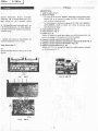
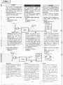
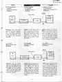
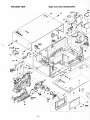
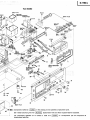
DISASSEMBLY
1.
Cassette tid
(Fig.
1l
2. Knob
*
The lever switch
knobs
(POWER,
MONITOR, BIAS.
EOUALIZER,
DOLBY-NR) and the
level adjustments
knobs
(OUTPUT,
RECORO
LEVELI are
pulled
off
from the front
of the front
panel.
t
Operating buttons, BIAS FINE adjustment knob,
MEMORY
button,
AUTO.REWIND
knob,
DCCS
button
and DCCS adiustment
knobs
are
removed after taking
off the
front
panel.
3. Top cover
(Fig.
2)
4.
Bottom
clvor
(Fig.
3l
5.
Front
panel
(Fig.
4, 5l
Remove
the front
panel
after
removing the
lever switch
knobs,
level
adjust-
ment knobs and the cassette lid.
6. Control
PC
Board
(Fag.
6l
7.
Biar
adjustmentflltlemory
PC
Board and DCCS
PC
Board
(Fig.
7)
8. Main PC Board
(Figs.
8, 9l
9. Cassette
chassir
(Figr.3,10)
Remove the 5
cassette chassis
installation
screws
shown
in the
figures
3 and 10.
BT3X
t2
Fig.2
Abb.2
BT3xl0
(with
lock
washer)
(hstaling
the cassett€
chassÈ)
AUSBAUANWEISUNG
1. Cassettenfachdeckel
(Abb.
1)
2.
Knópfe
*
Die
Knópfe
der Hebelschalter
(Net
tisierung, Entzerrung,
Dolby-NR) un
gangspegel,
Aufnahmepegel)
kónnen
abgezogen
werden.
*
Die
Funktionstasten,
der Vormagne'
Speichertaste, der
Knopf fúr
Rúcklaul
taste
und
der
Dolby-Kalibrierregler
sinc
nachdem
die Frontplatte
entférnt
wurd
3. Obere Abdeckung
(Abb.
2l
4.
Bodenplatte
(Abb.
3)
5.
Frontplatte
(Abb.
4,
5l
Die
Frontplatte
abnehmen,
nachdern
di
Pegeleinstellknòpfe
und der Cassettenfach
6. Regler-Platine
(Abb.
6l
7. Schaltplatine
und
Dolby-Kalibrier-Platine
8.
Haupt-Platine
(Abb.
8,
9)
9.
Cassetten-Ghassis
(Abb.3,
10)
Die
fùnf Befestigungsschrauben
des
Casse
Abbildungen 3
und 10
gezeigt
sind.
'\r
Fis.4 Abb.
4
83X25
BT3X;Z
(with
lock
washer)
L
It
I
I
t,
I
I
t
I
I
I
I
I
F-
I
I
Lú
-È..."
Fig.5 Abb.5
-5-

1)
relschalter
(Netischalter,
Monitor, Vormagne-
Dolby-NR) und
die Pegeleinstellknópfe
(Aus-
pegel)
kónnen
I
von der Frontplatte einfach
der Vormagnetjsierungs-Feineinstellknopf,
die
pf
fùr
Rùcklaufàutomatik,
die
Dolby-Kalibrier-
librierregler
sindivon
der
Rúckseite abzunehmen,
e entfernt wurdg.
ll
n, nachdem die
Knópfe
der Hebelschalter, die
:r Cassettenfach{eckel
entfernt wurden.
lalibrier-Platine
{AUU.
Zl
10)
i
auben
des
Cassetten-Chassis entfernen, die in den
reigt
sind.
':
,Frh:h.gais
DEMONTAGE
1. Volet
de
cassette
(Fig.
1!
2.
Boutons
de
réglage
*
Les
clefs
de
commutation
(POWER,
MONITOR, BIAS,
EOUALIZER,
DOLBY-NR)
et les boutons de réglase
(OUTPUT,
RECORD LEVEL)
sont retirés
par
le
panneau
avant.
*
Les interrupteurs
et
boutons de réglages BIAS FINE ADJ,
MEMORY,
AUTO-REWIND, DCCS et DCCS
sont retirés
du
panneau
arrière
après
dépose
de
la fagade.
3.
Plaque
supérieure
(Fig.
2l
4. Plaque inférieure
(Fig.
3)
5. Fagade
(Fig.4,
5)
Déposer
la
plaque
de fagade après
dépose
des clefs de commutation,
des
boutons
de réglages
et
interrupteurs
et du volet
de caSsette.
6.
Plaquette
à circtits
imprimós
de
commande
(Fig.
6)
7.
Plaquefte à circuits
imprimés
de
commutation
ot
Plaquette
de
DCCS
(Fig.
7)
8.
Plaquette à
circuits
imprimés
d'alimentation
(Fis.
8,
9l
9.
ChAssis de magnétocassette
(Fig.
3, 101
Dévisser
les 5
vis de
montage de
ch6ssis
de magnétocassette
indiquées
sur
les illustrations
3
et 10.
E}:}
X
8
(btack)
Fig. 10
Abb. 10
Fis.
9 Abb.9
-6-

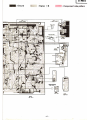
Schéma
Blockschema
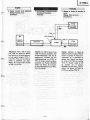
BTOCK DIAGRAM
F
t
0
t!
e.
o
o
f'
o
o
t-
-o
o
b
G
J
I
I
ff
J
6
I
i
àî9
Fq
2
r
6
NU
-I
at
o
F
=
o
E
z
ó
o
!
I
__l-
ao<
-.;Io
(
-u
e
bì6
ONI
F
)
o
2
c)
[,F
tt
>>
o
\t nF
""4
F
f
o
oP
g<
ed
oo
F<
u
I
È
U
t!
)
q
,lgi
-al
d1
.Rè
erÉ
oNx
ztt
-
--
q
r.t
R
))..
-N
l:
oo;
c
rl
nÍr
u!31
f3l
HI
I
i 9r
=H=h
ilF
E
g
-
.9
2
ts
z
U
É
5<f
35à
@:.
'
ÉgÈ
o
qX
J_
lI)o
go
N
G-o
JO
98
c
/(lúl
Yd
to
lo
E
;*
t
&fi
F
l!
rE
JG
q
<Ò
:31
o zl:
-U
oc
o
Otr
-)
ts
É.
"99
#l<
egff
gNF
u
E
o
oU
6È
)
o
oo9
-
r=
aò
-NF
:ot
<<fÉ
s{ji
rsSg
F
z
É
É
f
(_)
6
@
aE
5RE
óF()
=-Bg
;E
z
o
É
I
o
È
=
d
J]
oc
OF
-l
>o
e
o-
E
e€€
@;o9
!*64
i
|
.r..'.
e$8e
6
î
I
o
No-
<o
o=
o<
nt
oì
o
cd
JO
a3
tt
N
@
3
1".8
J€
oi
-I
E
l!
N
J
)
o
U
e
j
I
a
5$g
oÍ<
igs
;R"
J
z
o
6
o
É
d
J
9
F
Í
d.-
)
o
t.
J@
o\t
oo
-o
ON
-7-

Sch6ma
par
blocs
Levcl
valuor
droym ir
tùc
diagram erc
thc
pbybrck
output
levclr obtrhed by
plqtine
back
a tolt tapr MTT-150.
Recording
input
levclr are rot at
erdr
inpu!
terminal
ro thet
phyback
output
lcvelr
uring
th! t
rt
lrp. MTT-tf,
cln
bc obtrined.
c
o
F
9
o
z
Y
U
I
o
!
+
bq
!to
+U
o
ò
z
U
-J
o
a
U
Y
E
o
9a
:9
E 35
6eE
()
-o
PP
z
o
É
ì
I
ah
FÀ
rb
o
à8
àil
N5
=
É *FH
-oFo
g
=-BE
J
o
È
F
^z
"F8
I:u
o3F
=
RgH
ò-îe
BilE
(9
z
rl
FV
fL
D;
I
À
3g
F
;frÈ
P(,,
t!o
k0
d3
oo
<o
t!
I
fl
Ò
F
o
:E
o
ci
o
F
F
5
o
eE
oo
!c
sÉ
oì
l-U)
q.3
6;o
oN!
NI]
s89
oo5
EEH
fi6
FÈ
E:
d=
>-,
uÍ
z
9
UF
F<
t-z
U=
6=
@J.
<-l
o=
)
d
F
o
U
-@*
NÓC
"
-g
o
o-
gHu
I
60 0,^
o-60:
óNO(oÉ
{-!!T
oooó;î
6664t
NNNNE
òinóó'
o--oo
NNNN
tooo
z
o
tr
o
r!(E
FO
l!F
Òo
^uJ
Ir
9ú
i;o
9B
'rO
<=
oQ
oó
PA
YI
oo
9B-.o
N@O@Z
-!tfl=
oooo..f
60609
-onoì
-OOO;^
ogoo
ru
@6P
8[gÉ
o9
otr
=
-@
+
-<
y
gú
I
N}
-o
-F
!$
o-
c
o
c
ì
d
!1
oB
N
5u
o.ó
H'
-8-

^
,n
ft\
English
ADJUSTMENTS
Perform the following adiustments in
the
sequence stated after
cleaning the
head,
pressure
roller, and capstan
with a
head
cleaning stick moisted in
alcohol. Also,
unless
specially
indicated otherwise, set the switches
and controls to the
positions
indícated
in the table.
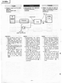
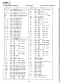
Adjustment
and semi-conductor
parts
location diagram
Abgleiche
Die folgenden
Abgleiche
in der auf-
gefiihrten
Reinhenfolge durchfiihren,
nachdem
die Tonkópfe,
die Andruck-
rolle
und die Tonwelle mit einem
in
Alkohol
angefeuchteten
Reinigungs-
stàbchen
gereinigt
wurden.
Wenn nicht
anders angegeben,
die Schalter
und
Regler
gemàB
nachfolgender Tabelle
einstellen.
Symbol
Nr.
Schalter
oder
Regler Position
s1 Netzschalter ON
s2
Dolby-NR OFF
s3 Monitor
TAPE
s4 Vormagnetisieru
ng UD.ER
(NOR)
s5
Entzerrung UO-ER
(NOR)
S6 Dolby
-Kalibrieru
ng OFF
sl2 Ausgangsschal ter
(W,
BS,
FSI
OFF
s14
Speicher
OFF
RVl Auf
nahmepegel(M
lC/D lN, Max.
RV2
Aufnahmepeget( LINEI Max.
RV4
Dolby
-Kalibrierungs-
Aufnahmepegel
Mittel-
stellung
RV5 Vormagnetisieru
ngs-
Feineinstell knopf
Mittel-
sîellung
RVlOO
Ausgangspegel Max.
Anordnung
der
Einstellelemente
.::::::::::::::.::::.::':.'::':::.:.:.:.:.È:
1!l,,,:..,
. i ::.
i.., i.::1i:::.::,1:,.:,..:
i,. i.i::..
REGLAGES
Procéder
aux
réglages suivants et
dans
l'ordre
sÉcifié après avoir
nettoyé
la
surface
des tétes magnétiques, du
galet-presseur
et le
cabestan avsc
un
bàtonnet
de nettoyage
à
embout
de
coton
imbibé
d'alcool.
Par
ailleurs, et
à
moins
qu'une
spécification
par-
ticulière
ne
soit
faite, régler les com-
mandes et interrupteurs
sur les
posi-
tions
spécifiées
dans le tableau.
Emplacement
des
semiconducteu
rs et
Réglage
-Record
level
odjusîmenî
A---.
urrent
odjuslmenî
Record level
o d
jus
îmen
t
Symbol
No.
Switch6
and
controls
Position
s1
Power
ON
s2 Dolby NR
OFF
s3 Monitor TAPE
S4 Equalizer
UD-ER
(NOR}
S5 Bias
UD-ER
(NORI
s6 DCCS
OFF
s12 DIN output
(W,
BS,
FS
onlyl
OFF
s14 Memory
OFF
RV1
Record level
(MlC/DlNl
MAX
RV2 Record
level
(LlNEl
MAX
RV4
DCCS Record
level Center
position
RV5
Bias fine
Center
position
RV1 OO
Output
level
MAX
No
d€
qymbole
lnterrupteurs
et
commandes
Positaon
s1 I nterrupteur
général
ON
s2 Dolbv NR
OFF
S3 Contróle TAPE
s4 Egaliseur
UD.ER
(NOR}
s5
Polarisation
UD.ER
(NOR}
s6 DCCS
OFF
s12
Commutateur de
sortie
(w,
Bs, Fs)
OFF
s14
Mémoire
OFF
RVl
Niveau d'enregis-
trement
(MlC/DlNl
MAX
RV2
Niveau
d'enregis-
trement
(LlNEl
MAX
RV4 Niveau
d'enregis-
trement DCCS
Position
c€ntrale
RV6
Régleur
Fin
de
polari-
sation
Position
centrale
RVlOO Niveau
de sortie MAX
",
-9-

zs(
I
v
iA
I
1
l
l
4
I
l
I
isi
lu
,u'
I
.
il
le,
te
I
i
,l
l
t
v
'a
il
-',
I
English
Next,
connect
the indicated
signal
source
and
meazuring
instruments
as
shown
in the
connection
diagram
for
each adlustment;
then
Perform
the
adiustment
as
described.
The adjustment
parts
are shown
in the
diagram
on
the
previous
Page.
1.
Tape speed
(motor
speed)
adjust-
ment
Setting
Playback
mode
Connection:
MTT-111
3000H2(31
50Hz')
Adjustment:
Warm up
the
unit
for
approxirpately
20 minutes; then
playback
test tape MTT-I 1 I,
3000H2(3150H2*),
and measure
the
speed deviation with a frequen-
cy counter.
lf required. adjust the
semi-variable resistor on the motor
for
a
reading
of 3000H2(3150H2*).
Carry out the
measurement
at the
middle of the tape.
2. Head azimuth
adiustment
Setting:
Playback mode
Connection:
MTT.114
10
kHz
Adjustment:
Use
the
HITACHI
head adjusting
jig
and
instructions.
(Consult
nearest
H ITACH
I
off ice.)
To obtain
the
correct head height,
tilt and
azimuth.
This adlustment
has
to be done
alternately.
Then,
use
test
tape
(MTT-'l
14, 10
kHz)
to adjust
the azimuth
of
Record/
Playback
head
by means
of
the
adjusting
screw
"a"
for
maximum
output.
Danach die
angegebenen Signalquellen
und MeBinstrumente
gemàB
der
Diagramme
fúr
die
einzelnen
Ein-
stellungen
anschlieBen
und
die
Ein-
stellungen
durchfiihren.
Die Einstellteile
sind dem
Diagramrn
auf
der vorhergehenden
Seite
zu
entnehmen.
1. Bandgeschwindigkeit
(Motordreh-
zahll
Einstellung:
Wiedergabe
Anschlússe:
LINE
OUT
jacks
Abgleich: Das Geràt
fúr
etwa
20
Minuten warmlaufen
lassen; danach
das Prúfband
MTT- 1 1 1, 3.000 Hz
(3150H2*)
abspielen
und die Ges-
chwindigkeitsabweichung
mit
ein-
em
Frequenzzíhler
messen. Wenn
erforderlich,
den
Regelwiderstand
am Motor
nachjustieren.
bis der
Frequenzzàhler
3.000H2
(31
50Hz
*)
anzeigt.
Die Messung in der Mitte
des Tonbandes vornehmen.
2.
Tonkopfazimut
Einstellung: Wiedergabe
Anschlihse:
Brancher ensuite la
source
de
signal re
commandée et les appareils
de
mesures
comme indiqué
sur
le
schéma
de
branchernent
et réaliser les
réglages
comme décrit.
Les organes
à régler sont
indiqués
sur
le
schéma de
la
page
précúJente.
1. Réglage
de vitesse
de défilement
de
bande
(Vitesse
de rotation
du
moteur)
Réglage: Mode
de lecture
Branchement:
*
According
to
DtN
45
500.
Réglage:
Laisser chauffer
l'appareil
pendant
environ
20
minutes
Puis
lire
une bande
de
contrÒle
MTT-
1 1
1. 3000H2(3150H2*)
et
mesurer
l'écart
de vitesse
avec
un compteur
de
fréquence.
Au besoin, ajuster
la
résistance
semi-variable
du moteur
pour
obtenir
une indication
de
3000H2(3150H2*).
Effectuer les
mesures
en
milieu de
bande.
2. Réglage
d'azimuth
de téte
magné-
trque
Réglage:
Mode de lecture
Branchement:
Top
view of
Record/Playback
head
R égl age:
Utiliser le
gabarit
de réglage
de
téte
HITACHI
et lire les instructions
(consulter
le service HITACHI
le
plus proche
de chez vous). Pour
obtenir un réglage
précis
de la
hauteur de téte,
l'inclinaison
et
l'azimuth,
ce réglage
doit étre fait
alternat ivement.
Ensuite,
utiliser une bande de
con-
tròle
(MTT
1
14, 1OkHz)
pour
ajuster l'azimuth
de la
tète combi-
nqee
enregistrement/lecture en
utilisant
la vís
"a"
pour
obtenir
un
niveau
de sortie maximum.
1
1
I
Absleich:
Die H
ITACH
I
-Tonkopf-Einstellehre
verwenden
(wenden
Sie sich an die
nachste
HITACHI
Vertretung)
. Um
richtige
Tonkopf
hòne,
Tonkopgnei-
gung
und
Azimuteinstellung
zu
erhalten,
muB
dieser Abgleich
eini-
ge
Male
wiederholt
werden.
Danach
das Prùfband
(MTT-114,
10
kHz)
abspielen
und
den Aufs-
prech-/
Wiedergabekopfazimut
mit
Hilfe der
Schraube
"a"
einstellen,
bis maximaler
Ausgangspegel
ge-
wahrleistet ist.
1
't
-10-

A
^
Engfirh
3.Souro
moniior
lewl
rdiu*ment
'
Srttinfr
Plóyback mode
Conncctbn:
3.
Monitorpegcl
(VoÈandkontrollel
E inrtellung:
Wiederyabe
Anrdrlible:
3.
Róchge
dc
nivcru
dc
comr0lc dr
toutoe
Róghgo:
Mode
de legture
Branc-lrement:
t
Róglage:
Appliquer
un signal
de
400H2
à
l'entrée
de ligne
LINE lN.
Ajuster
le
bouton
de
niveau
d'en-
registrement sur le
générateur
de
signaux
pour
obtenir
une
tension
de sortie
de
O,775Y aux
broches
TP1L, R. Ensuite,
régler
la
clef
de contróle
sur la
position
SOURCE et
ajuster
RT2{L,
R)
pour
obtenir une
tension
de sortie
de
O,775V
aux broches
TP3L,
R.
,+7ìì
Adjurtment: Feed
a
400
Hz signal
into
LINE
lN.
Adjust the Record
level
control
or
the signal
generator
so
that
output
voltage
at TPl L,
R
is
0.775V. Then, set
the
Monitor
switch to SOURCE and adiust
RT2(L, R)
so that ouîput
voltage
at TP3L, R is
0.775V.
Abgleich:
Ein
400
Hz
Signal an den
LINE
lN
Buchsen
einspeisen.
Den
Aufnahmepegelregler
oder den
Si-
gnalgenerator
einstellen,
bis eine
Ausgangsspannung
von
O,775Y an
TPlL,
R
anliegt.
Danach
den Moni-
torschalter
auf Position
SOURCE
stellen
und
RT2(L,
R)
einstellen,
bis die
Ausgangsspannung
an TP3L,
R
0,775V
betràgt.
TPlL. R
LINE
lN
ia<
ks
TP3L,
R
D-980u
Attenuator
{
È-
A".\,
-
11
-

Englistr
4. Playback
output
and
VU
adjustment
Setting
Playback mode
Connection:
4. Wiedergabepegel
und
Pegelmesser
Einstelluqg
Wiedergabe
Anschlibse:
4.
Róglage de
niveau
de
roÉie
ds
lecture
et dlindicatsurs
de nireau
Réglage:
Mode de lecture
Branchement:
TP3L,
R
motetr
:s
I
\
s
IU
VI
LINE
lN
jacks
VTVM
Attenuator
D-980n
I
Abgleich:
1l Monitorschalter
auf
Position
SOURCE
stellen.
Ein
400 Hz
Signal
an
den LINE
lN Buchsen
einspeisen
und
den
Signalge-
nerator
einstellen,
bis an
den
Stiften
TP3L,
R
eine
Ausgang-
sspannung
von
0.775V
anliegt.
2l Danach
RT103(L,R)
einstéllen,
so
daB
die
Anzeigenadeln
der
lnstrumente
bis zue
DolbY-Mar-
kierung
(ll[
)
ausschlagen.
3)
Danach
den
Monitorschalter
auf
Position
TAPE
stellen.
Ein
Prùf-
band
(MTT'150,
400
Hz, 2Om
Maxwell)
absPielen
und
RT100
(L,R)
einstellen,
so
daB die
Anzeigenadeln
der
lnstrumente
bis zur Dolby-Markierung
(
[f
]
ausschlagen.
Réglage:
1)
Régler
la
clef
de
contrÒle
slr
la
position
SOURCE.
APP|iquer
une
signal
de
400H2 à
l'enÎrée
de'ligne
LINE
lN et ajuster
le
générateur
de
signaux
Pour
obtenir
uné
tension
de sortié
de
O,775V
aux
broches
TP3L, R.
2)
Aiuster
ensuite
RT103(L,Rl
Pour
que
les
aiguilles
d'indicateurs
viennent
se
Placer
rur
le sYmbole
(DC
t
ootov.
3)
Régler
la
clef
de
contrÒle
sur
la
position
TAPE.
Lire
une
bande
de
contròle
(MTT-150,
400H2
20m
Maxwell)
et aiuster
RT100
(L.R)
Pour
que
les aiguilles
d'indicateurs
viennent
se
Placer
en
face
du
sYmbole
(
DC
I
DolbY.
I
I
I
MTT.I50
400H2,20m
Maxwell
Adjustment:
1)
Sct
the Monitor
switch
to the
SOU
RCE
position.
Feed a
400H2
signal
into
LINE
lN
and
adjust
the signal
generator
so
that
output
voltage
at TP3L,
R
is
0.775v.
2)
Then, adjust
RTl03(L,Rl
so
that
the
meter
indícators deflect
to the
Dolby
marks
(D[
).
3)
Set
the Monitor
switch
to the
TAPE
position.
Playback test
tape
(MTT-150,
400H2
2Om
Maxwelll
and adjust
RT100(L,R)
so
that
the
meter
indicators
deflect
to the Dolby
marks
(DC
).
-12-

English
5.
Bias current, record
lewl adjust-
ment
Setting:
Recording/Playback
mode
Connection:
5.
Vormagnetisierungsstrom,
Aufnah-
mepegel
Einstellung:
Auf
nahme/Wiedergabe
Anschlússe:
LINE
lN
jacks
Abgleich:
1)
HITACHI
UD-ER
C-90
Cassette
verwenden.
2)
Den
Monitor-Schalter
auf
Posi-
tion
SOURCE
stellen und ein
400 Hz
Signal an den
LINE
lN
Buchsen
einspeisen.
Danach
das Dampfungsglied
des
Signalgenerators
so abgleichen,
daB die
VU-Meter
des Geràtes
einen Pegel
von
O
VU
anzeigen.
AnschlieBend
den Monitor-
Schalter
auf
Position
TAPE
stellen
und
RV4
(L,
R
-
DCCS)
so
abgleichen, daB
die VU-
Meter
einen
Pegel
von
O
VU
anzergen.
3) Den
Monitor-Schalter
auf
Po-
sition
SOURCE
stellen, ein 1,2
kHz
Signal
an den LINE
lN
Buchsen
einspeisen und das
Démpfungsglied
des
Signal-
generators
so einstellen, daB
die
VU-Meter
einen
Pegel
von
O
VU
anzeigen.
Die Anzeige des
Ròhrenvoltmeters
beachten
(diese
Anzeige ist der Standard-
Aufsprechpegel:
A dBl.
4)
Den Monitor-schalter
auf
Position
TAPE
stellen
und
RT5
(L.
R)
so abgleichen. daB
das
Róhrenvoltmerer
-1
dB
ge-
genúber
dem
Maximalwert
anzei-
gt.
5.
Réglage
de
niveau
d'enregistremant
et de
courant
de
polariration
Réglage:
Mode
d'enregistrement/
lecture
Branch€m€nt:
LINE
OUT
iacks
Réglage:
.l
)
Utiliser
une bande HITACHI
UD-ER
C.90.
2)
Régler l'interrupteur
de contròle
sur la
position
SOURCE.
Ap-
pliquer
un signal
de 400H2
à
la
borne LINE
lN et
ajuster
l'atténuateur
du
générateur
de
signal
pour que
les
VU-mètres
indiquent
0
VU.
Régler ensuite l'interrupteur
de
contròie
sur
la
position
TAPE
et ajuster
RV4
(L.R
DCCS)
pour que
les VU-mètres
indi-
quent
0
vu.
3)
Régler I'interrupteur
de contròle
sur la
position
SOURCE et
appliquer
un signal
de 1,2kHz
à
la
borne
LINE
lN
et
ajuster
I'atténuateur
du
générateur
de
signal
'pour
que
les
VU-mètres
indiquent
0
VU.
Observer
le
voltmètre électronique
(l'indica-
tion
obtenue correspond
au
ni-
veau
normal d'enregistrement
A dB}.
4) Régler l'interrupteur
de contròle
sur la
posltion
TAPE
et ajuster
RTs
(L,Rl
pour que
le
volt-
mètre électronique
indique
-1dB
à
partir
de l'indication
maximale.
^
^
a,
.rl
Adjustment:
1) Use
HITACHI UD-ER C-90
tape.
2) Set
the
monitor switch to the
SOU
RCE
posítion
and
feed
400H2
signal
into LINE lN
and adjust the attenuator
of the
signal
generator
so that
the
VU
meters
of the set
indicate
0VU.
Then, set the monitor
switch
to
TAPE
position
and
adjust RV4
(L,R-DCCS)
so that.the
VU
meters indicate
OVU.
3)
Set the monitor
switch to
SOU RCE
position
anci
feed
1.2kHz
signal
into
the LINE
lN
and adjust
the attenuator
of
the
signal
generator
so that
the VU
meters indicate
0VU.
Observe VTVM
(This
indication
is the
standard recording
level:
A
dB).
4)
Set the
monitor switch
to TAPE
position
and
adjust RT5(L,R)
so
that
the VTVM
indicates
-1dB
from
the
maximum
indi-
cation.
MAX
rM9[
r-
-
1--
-
1dB
F
f,
o-
F
l
o
,t\
BIAS
CURRENT
-13-

I
English
5)
Set
the
monitor
switch
to
SOURCE
position.
Reduce
the output
of
the signal
generator
(Adiust
the
attenuator
of
the signal
generator
)
so that
the
VTVM
indicates
-20
dB
from the
standard
recording
level
A.
Then, set
the
monitor
switch
to
TAPE
position
and observe
rhe
VTVM
(This
indication
is
B
dB).
6)
Set
the
monitor 'switch
to
SOURCE
position.
Feed
12kHz
signal
into
LINE
lN
and
adjust
the attenuator
of
the
signal
generator so
that
the
VTVM
indicates
-20
dB
from
the
standard
recording
level
A.
set
the
monitor
switch
to TAPE
position.
Then,
ensure
that
the
VTVM
indicate
811.5d8.
lf not,
readiust
RT5(L,R)
at
this
condition.
7) Confirm
the
adjustment
for
CrO2
tapes
bY
the
following
steps.
Use
HITACHI
UD-EX
C-90
tape.
Set
the
equalizer
and
bias switch
to CrO2
Position.
Adjust
RT3(L.R)
bY steP
(2)'
Then,
repeat
steP
(3)
bY
1 kHz
signal
and
(5).
8)
Set
the
monitor
mritch
to
SOURCE
Position.
Feed
16
kHz
signal
into
LINE
lN
and
adiust
the
attenuator
of
the
signal
generator
so
that
the
VTVM
indicate
-20
dB
from
the
standard
recording
level
A.
Set
the
monitor
switch
to
TAPE
position
and
ensure
that
the
VTVM
indicates
B
11.5 dB.
lf
not.
readiust
RT4
at
this
condition.
5l Den Monitor-Schalter
auf
Posi-
tion
SOURCE
stellen.
Den
Ausgangspegel
des Signalgenera-
tors reduzieren
(das
Dàmpfungs-
glied
des
Signalgenerators
eins-
tellen), so
daB das
Ròhrenvolt-
meter
-20
dB
gegeni.iber dem
Standard-Aufsprechpegel
A
an-
zeigt.
Danach
den
Monitor-Schalter
auf
Position TAPE
stellen
und
die
Anzeige
des
Ròhrenvolt-
meters
beachten
(diese
Anzeige
betràgt B
dB).
6)
Den
Monitor-Schalter
auf
Po-
sition SOURCE
stellen,
ein
12
kHz
Signal
an
den
LINE
lN
Buchsen
einsepisen
und das
Dàmpfungsgl ied des
Signalgenera-
tors
so einstellen, daB das
Ró-
hrenvoltmerer
-20
dB
gegenùber
dem
Standard-Aufsprechpegel A-
anzeigt.
Danach
den Monitor-
Schalter
auf
Position
TAPE
stellen.
Darauf achten, daB das
Róhrenvoltmeter
einen
Pegel
von
B
11,5
dB anzeigt; wenn
nicht.
RTs
(L,
Rl
nochmals
nachjustieren.
7) Den
Abgleich fúr CrO2-Band
wie
folgt Kontrollieren :
HITACHI
UD-EX C-90 Cassette
verwenden
und die Wahlschalter
fúr
Entzerrung und Vorm-
agnetisierung
auf
Position
CrO2
stellen. Danach RT3(L,R)
gemàB
Schritt
(2)
abgleichen. Anschlie-
Bend
die
Schritte
(3)
mit
einen
1-kHz
Signal und
(51
wieder-
holen.
8)Den
Monitor-Schalter auf
Posi-
tion
SOURCE stellen,
ein
16
kHz
Signal an den
LINE lN
Buchsen
einspeisen
und das
Dàmpfungsglied des Signalgener-
ators
so einstellen,
daB das
Róhrenvoltmeter einen
Pegel
von
-2O
dB
gegeniiber
dem
Standard-Aufsprechpegel A an-
zeigt.
AnschlieRend
der
Monitor-Schal-
ter
auf
Position
TAPE stellen
und darauf
achten,
daB das
Róhrenvoltmeter einen
Pegel
von
B
tl
.5
dB anzeigt,
Wenn
nicht,
RT4 in diesem
Zustand
nachjustieren.
'.'
.,.,,,,:,i:lll:,:,'.....,,,,,,:::,'..,,,,,:lÉtf$
i$l::.:iiìl':ii::'iii.:.:i:.:i;::.'ì,':i:..;.l,l..,i:,..i::::.:::
5)
Régler
l'interrupteur
de contròle
sur
la
position SOURCE,
dimi-
nuer
la niveau
de
sortie
du
gé-
nérateur
de signal
(ajuster
l'at-
ténuateur
du
générateur)
Pour
que
le voltmètre
électronique
indique
-20dB
à
Partir
du
niveau
normal d'enregistrement
,
A.
Ensuite,
régler l'interrupteur
de
contrÒle
sur la
position
TAPE
et observer
le voltmètre
élec-
tronique
(Cette
indication cor-
respond à B dB).
6)
Régler
l'interrupteur
de contròle
sur
la
position
SOURCE
et
appliquer
un
signal de
12 kHz
à
la borne
LINE
lN et ajuster
I'atténuateur
du
générateur
de si-
gnal
pour que
le
voltmètre
électronique
indique
-20dB
à
partir
du
niveau normal d'enregi-
strement
,A
.
Régler I'interrup-
teur de
contróle sur
la
position
TAPE.
Ensuite, voir si
le
volt-
mètre
indique
Bì1,5
dB. Dans
le cas
contraire,
réjauster RT5
(L,R
en conséquence.
7l Confirmer
le
réglage
avec
des
bandes
CrO2
en
Procédant
com-
me
suit.
Utiliser
une
bande
HITACHI
UD.EX
C.90.
Régler
l'interrupteurs
de
Polari-
sation
et
d'égalisation
sur
la
position
CrO2.
Ajuster
RT3
(L,R)
en effectuant
l'oPération
t2t.
Répéter
l'opération
(3)
en
appliquant
un signal
de
1 kHz
et
opération
(5).
8)
Régler
I'interrupteur de contròle
sur la
position
SOURCE. Ap-
pliquer
un signal de
16kHz
à
la
borne
LINE
lN
et ajuster
I'atténuateur
du
générateur
de
signal
pour
que
le voltmètre
électronique
indique
-20dF
à
partir
du niveau
normal d'enre-
gistrement
A .
Régler I'interrup-
teur de
contrÒle sur
la
posi-
tion
TAPE et voir si
le
volt-
mètre
électronique
indique
Bt1.5
dB.
Dans
le cas contraire,
réaluster
RT4
en conséquence.
-t4-

D-98Otrt
^
English
6.
Dolby
NR adiustment
6.-l Record
Setting:
Recording
Mode
Connection:
6.
Réglage de Dolby NR
6.-1
Enregistrement
Réglage:
Mode
d'enregistrement
BÌanchement:
TP1L, R
(TP2L,
R)
^
A
Adjustment:
Feed a
SkHz
signal
into LINE
lN,
so that the
voltage at
TPl L, R becomes
-30.4dBm.
Then, set the
DOLBY NR
Switch
to ON.
Adjust RTl(L,R) so
that
the voltage
at îP2L,
R becomes
-22.4dBm.
6.-2
Playback
Setting
Playback
mode
Connection:
Réglage:
Appliquer
un signal
de
$H.
ru"
prises
d'entrée
de
ligne
LINE
lN
pour
que
le niveau
de
sortie
aux broches
TP1L. R soit
égal
à
-30.4
dBm.
Ensuite, basculer
la
clef
de
commutation
de Dolby
sur
ON.
Ajuster
RTl
(L,
Rl
Pour
que
le niveau
de sortie auxbroches
TP2L,
R soit
égal à
-22.4d8m.
6.-2
Lecture
Réglage:
Mode
de lecture
Branchement:
TP3L,
R
(TP4L,
R)
Abgleich:
Den Monitorschalter
auf
Position
SOURCE stellen
und ein
SkHz
Signal
an den LINE
lN
Buchsen
einspeisen,
so daR der
Pegel
an TP3L,
R
-22.4dBm
betràlgt.
Danach den
Dolby-NR-
Schalter
auf Position
ON stellen
und RT101
(1,
R) einstellen, bis
der
Pegel
an TP4L,R
-30.4d8m
betragt.
Réglage:
Régler
la.clef
de contróle
sur
la'
position,
SOURCE et
ap-
pliquer
un signal de
5 kHz aux
prises
d'entrée
de
ligne
LINE lN
pour
que
le
niveau de sortie aux
broches
TP3L,
R soit égal à
-22.4
dBm. Ensuite, basculer la
clef de
commutation,de
Dolby sur ON et
ajuster
RT10î
(L,
R)
pour
que
le
niveau de sortie aux borches TP4L,
R
soit égal
à
-30.4
dBm.
'l:il:i::::::::::::j:::1:
::.::::::Jl:
: .::::'.:::r::l:::,
::::::: :j
.::
.
: ::
6.
Dolby-NR-Abgleich
6.-1 Aufnahme
Einstellung:
Aufnahme
Anschliisse:
LINE
lN
jacks
Abgleich:
Ein 5
kHz
Signal
an
den
LINE
lN
Buchsen
einsPeisen,
so
daB
der
Pegel an
TP1L,
R
-30'4
dBm
betràgt.
Danach
den
DolbY-
N R-schalter
auf
Position ON
stellen.
RT1
(L,
R)
einstellen,
so
daB der
Pegel an
TP2L,
R
-22.4
dBm
betràgt.
6.-2 Wiedergabe
Einstellung: Wiedergabe
Anschlússe:
t^\
Adiustment:
Set
the Monitor
switch
to the
SOURCE and
feed
5kHz
signal
into
LINE lN, so that
the voltage
at TP3L,
R becomes
-22,4dB,m.
Then, set the
Dolby
switch
to ON, and
adjust RT101
(L,
R) so that the
voltage at
TP4L,
R becomes
-30.4
dBm.
-15-
l
VTVM
-30.4
dBm/
-22.4d9m
D-980u
/
Attenuator
{
{
I
J
LINE
lN
jacks

D-980
m
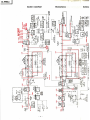
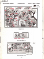
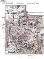
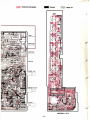
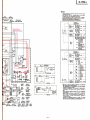
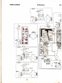
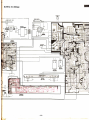
CIRCUIT
BOARD
DIAGRAM
Printplattenansicht
Schéma
de
plaque
de càblage
POWER
P.C.B.
PEAK INDICATOR
P.C.B.
MOTOR CONTROL
P.C.B.
-16-
ffi
v
v
\/
:
Ground
:
Signal,
+B

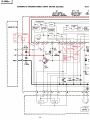
D-980m
CIRCUIT
BOARD
DIAGRAM Printplattenansicht
Schéma de
plaque
de
càblage
r--
--
I
I
otru
LUO
ÎERMINAL
LI NE IN
LINE OUT
-17
-
MAIN P.C.B.

:
Componcnt
tide
p.tùm
I:
Ground
I
{\
J
RE@RD
LINE
RECORD
MIC,/DfN
-18-
CONTROL
P.C.B.
J

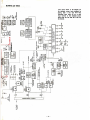
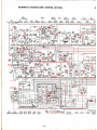
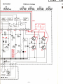
SCHEMATIC
DTAGRAM (AMP./CONTROL
SECTTON)
S
ol5
Dt5
Dt4 0t
t4L
tc tL
zSCl 7.tO
HV-46 I
S2473 2SK6€A-N
HAt406
SWITCHING
SìWITCHING
SWITCHING HEAD AMP MIC,/DIN AMP
O3L
Dlz OIL
2SC45€LG
ts2473
2SC45aLG
LINE AMP
MIC./DIN
AME
tc3L
otooL
OtOtL
otozL
EAI4OE
2SD467
2s,D46?
2SC\74O
HEADAMP
SWITCHING
SWITCHING
LINÈAMP
o4L tc2
DtL
25D467
HA||226
tN34A
SWITCHING
REC DOLBY NR
RECT FOR
DOLBY
oro3L
tc4
DtooL
Ot
I
2SD467
HAt t226
rN34A
2SC
SWITCHING
PLAY
OOLBY NR RECÎ
rcR
DOLBY
B IAS
]
o6
2SCt
740
DCCS 4OOHZ
OSc
Q2L
2SCt740
BACK C
I
Dr3
I
32473
L"l-
r
CHECK
f6s-ì
t-
c4 I
I
I
I
TMrTI
lrar"l
I'-
FGîl|lF
I
I
I
L:
(
):D!.lnt
't4dht
D30t tc300
LEO300 LED3o|
ts2473
HAt200t
GL-3P
GL-3P
SWIICHING
II,IODE
CONTROL'PAUSE'
-REC'
0300
ts2473
RECI
DI23 L
I 52474
REÒT.
oll2,Dt27
Dl50 0il3
ts2473
rS2473HC
2SCt740
AUTO STOP
DEI
0il3,Dil4
02t4,D2
rs2076 awor-
\ÓLT. STA
t_
-19-
LED3O2
GL-3P
'PLAY'

oll2
Qro4L
Qtz
DtO7,Ol.oe,DEt,Dt22
oilO
OiltL
29Cl?
13
2SCr74o
?Sct
t62
ts2473
25A673
2SD467
BrAs
@NTRoL HEADPHoNEaMe
voLT:sîAB
ÉEói.
swlrin-rnc
ùúÍiùò
Stromlaufplan
DlOl
L
DzL
Ot2O
OsL
l_. _.. __-ls_?tz3
ts2473
HV_46 esCtT+o
DoLBy REcr
FoR
Dolay
REcr FoR
oot-.By
iiÈci_
REc.- Éii. lúúp.
Q207
02t
r
o20s
0208
2SC458p
-
D zsct2t 3C 2SD468B
2SD468B
------------5WmFIN6-ERT--
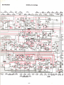
Schéma
de montage
Dt5t
I
s2473HC
LED I
LED2
LED3 LED4
sLP-248
SLP-248 SLp-22451
SLp-248
'tNPUT'
"souRcE"
-ourpur"
'REc"
0206
q209
02ro
Q2t2
.2SD4688
2SD46AB
2cC458 2SCt2t3C
ffi
_Qlo
Dro
qlo6
Dl r
Dr6
0t
I
*t,tfCÍî8n
*.*
..lF"tolrt."..*
r?tr?'rtXoue
t'tff#"1"n
.lfl?rl'"n rfrîféiî8"
olo7,oto8,ot09
Dt3()
2SCt7.lO
AwOt-7
PROTECTÍn
^_
IB
Dil5
D2t2 02||
D2t8 0204
JS2473
ls2473,vo6c
ts2473
2*t2t3c
swricxrrue
\o{-f
srAB.
vt3,@t4
HZ-9
\0-T. SIAV.
-'l
I
I
I
1
I
I
I
I
J
,
D2t5
)t- 7
STAB.
-20-
LEDs
0200
0205
st-P-22481
2SCil62
HZ-ts
'PLAY"
\rcLT.
sraB. voLt sraB
o20
2SCt
I
\OLT- S
Seite laden ...
Seite laden ...
Seite laden ...
Seite laden ...
Seite laden ...
Seite laden ...
Seite laden ...
Seite laden ...
Seite laden ...
Seite laden ...
Seite laden ...
Seite laden ...
Seite laden ...
Seite laden ...
-
 1
1
-
 2
2
-
 3
3
-
 4
4
-
 5
5
-
 6
6
-
 7
7
-
 8
8
-
 9
9
-
 10
10
-
 11
11
-
 12
12
-
 13
13
-
 14
14
-
 15
15
-
 16
16
-
 17
17
-
 18
18
-
 19
19
-
 20
20
-
 21
21
-
 22
22
-
 23
23
-
 24
24
-
 25
25
-
 26
26
-
 27
27
-
 28
28
-
 29
29
-
 30
30
-
 31
31
-
 32
32
-
 33
33
-
 34
34


Hitachi D-980MAU Benutzerhandbuch
- Typ
- Benutzerhandbuch
in anderen Sprachen
- English: Hitachi D-980MAU User manual
- français: Hitachi D-980MAU Manuel utilisateur
Verwandte Papiere
Sonstige Unterlagen
-
Akai EA-A2 Benutzerhandbuch
-
Dometic RainTec RT100 Installationsanleitung
-
Hama 00005201 Bedienungsanleitung
-
Sanyo M2541Z Instruction book
-
Denon DRM-550 Operating Instructions Manual
-
Yamaha W321 Bedienungsanleitung
-
Aiwa AD-F 800U Bedienungsanleitung
-
JVC KD-A55 Bedienungsanleitung
-
-