
SERVICE MANUAL
English
Deutsch
Frongois
No.
I l5ó
English
This unit
employs the UD-1 standard
mèchanism.
When
inspecting and
re-
pairing
this unit, read this
together
with
the service manual
(No.
1
155)
of
the UD mechanism
(UD-1).
USA
Canada
General
Area
Switzerland
and Scandinavia
Great Britain
Australia
D ieses
Geràt ist
mit
der
Standard-
Mechanik
UD-1
ausgerústet.
Fùr
Prúfung
und
Eeparatur
dieses
Geràtes
ist daher
die
vorliegende
Anleitung
gemeinsam
mit
der
Wartungsanleitung
(Nr.
1155)
fúr die
UD-Mechanik
(UD-1
)
zu
verwenden.
USA
Kanada
Allgemeine
Gebiete
Schweiz und
Ska
nd inav
ien
G
roBbritannien
Australien
Cet appareil est équipé du
dispositif
standard UD-l. Au
moment de
procéder
à une remise en état
ou une
inspection
de l'appareil,
veuillez
prendre
connaissance du texte suivant
et du
Manuel
d'entretien
(No
11551
pour
dispositif
UD
(UD-l).
Remarque:
U..... Etats-Unis
C..... Canada
W Tous
pays
FS
. . . . Suisse et Scandinavie
BS
. . . .
Grande-Bretagne
AU Australie
STEREO
CASSETTE
TAPE
DECK
SAFETY PRECAUTION
The
following
precautions
should be
observed when servicing.
1.
Since
many
parts
in the unit
have
special safety
related charac-
teristics,
always
use
genuine
Hitachi's
replacement
parts.
Especially
critical
parts
in the
power
circuit
block should
not be
replaced
with
those
of other
manufacturers.
Critical
parts
are
marked
with
A
in
the schematic
diagram,
and
circuit board
diagram.
2.
Before
returning
a repaired unit
to
the customer,
the service
tech-
nician
must
thoroughly
test the
unit
to ascertain
that
it is com-
pletely
safe to
operate without
danger
of electrical shock.
Bei
Wartungsarbeiten
sind
die
folgenden
SicherheirmaBnahmen
zu
beachten:
1. Da
verschiedene
Teile dieses
Geràtes
Sicherheitsfunktionen
auf-
weisen,
nur
Original-Hitachi-
Ersatzteile
verwenden.
Kritische
Teile
im Netzteil
sollten
nicht
durch
àhnliche
Teile
anderer
Hersteller
ersetzt
werden.
Alle
kritischen
Teile sind
im
Schalt-
plan
und
im Diagramm
der
Schaltplantinen
mit
dem
Symbol
I
gekennzeichnet.
2.
Yor
der
Auslieferung
eines
reparierten
Geràtes
an den
Kunden
muB
der
Wartungstechniker
das
Geràt
einer
grúndlichen
Prúfung
unterziehen,
um
sicherzustellen,
da8
sicherer
Betrieb
ohne die
Gefahr
von
elektrischen
Schlógn
gewàhrleistet
ist.
Les
pécautions
suivanÉs doivent
étre
observées
à
chaque
qu'une
réparation doit
étre faite.
1.
Etant
donné
que
de
nornbreux
cqnposants
de
l'appareil
possèdent
des
caractéristiques
r€-
latives
à la sécurité,
utiliser
uniquement
des
pièces
de
rechange
d'origine
Hitachi
pour
effuctuer
un remplcement.
Ceci
se rapporte
notamment
aux
pièces
critiques du bloc
d'alimentdtion
qui
ne doivent
en aucun
cas étre
remplacées
par
celles d'altres
fabricants. Les
pièces
critiques
sont
ccompagnés du
symbole
A
d"nt le
sclréma de montage
et
sur le schéma de
plaque
de
càblage.
2. Avant
de retoumer
l'appareil
réparé
au client, le
technicien
doit
prooéder
à
un
essai
conplet
pour
s'asilrer
que
l'appareil ne
pÉsente
ancun danger de
chocs
électriques.
Jan.
1
979

I
I
1
i
I
!
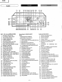
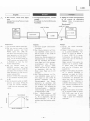
KEY
TO
ILLUSTRATIONS
1 RECORD
INDICATOR
2 PLAYBACK
INDICATOR
3
PAUSE
INDICATOR
4 3.HEAD
INDICATOR
5
TAPE COUNTER
6 COUNTER
RESET
BUTTON
7 AUTO.REWIND
SWITCH
8 BIAS
FINE ADJUSTMENT
KNOB
9 MEMORY
SWITCH
1O VU
METER
(LEFT)
11
PEAK
INDICATORS
12
VU
METER
(RIGHT)
13 DCCS
CONTROLS
14
OUTPUT
LEVEL
CONTROL
15
RECORDING
LEVEL
CONTROLS
16 RECORDING
LEVEL
CONTROLS
17 MONITOR
S1/VITCH
18
DOLBY NR
SWITCH
19 TAPE
SELECT
SWITCH
(EOUALIZER)
20 TAPE
SELECT
SWITCH
{BIAS)
21
EJECT BUTTON
22
REC
MUTE BUTTON
23
PAUSE
BUTTON
24 STOP
BUTTON
25
FAST
FORWARD BUTTON
26
PLAYBACK
BUTTON
27 REWIND
BUTTON
28
RECORD BUTTON
29 HEADPHONE
JACK
30 MICROPHONE
JACK
(RIGHT}
31
MICROPHONE
JACK
(L/mono)
32 POWER
(MAINSISWITCH
Bezeichung
der
Bedienungsele'
mente
1
Aufnahme-Kontrollampe
2
Wiedergabe-Kontrollampe
3
Pausen-Kontrollampe
Kontrol
lampen
fúr DreikopfbestÚckung
Bandzàhlwerk
Bandzàh
lwerk-Nu
llstel
ltaste
Schalter
fúr Rúcklaufautomaiik
Vormagnetisierungs-Feineinstel
lknopf
Speicherschalter
VU-Meter
(linker
Kanal)
Spitzenwertanzeiger
VU-Meter
(rechter
Kanal)
Do
lby-Kal
ibrierreg
ler
Ausgangspegelregler
Auf
nahmepegelregler
Aufnahmepegelregler
Monitorschalter
Dolby-N
R-Schalter
1 9
Entzerrungs-Bandsortenwàhler
20
Vormagnetisierungs-Bandsortenwàhler
21
Auswerftaste
22
Aufnahme/Muting
23
Pausentaste
24
Stopptaste
25
Schnellvorlauftaste
26
Starttaste
27
Rúcklauftaste
28
Aufnahmetaste
29
Kopfhórerbuchse
30
Mikrofonbuchse
(rechter
Kanal)
31
Mikrofonbuchse
(linker
Kanal/Mono)
32
Netzschalter
Guide
des
illustrations
1
Témoin
d'enregistrement
2 Témoin
de
lecture
3
Témoin
de
pause
4 Témoin
3
tètes
5 Compteur
de
longueur
de
bande
6
Bouton
de
remise
à zéro
du
compteur
7
lnterrupteur
de rebobinage
auto-
matique
8
Bouton
de
réglage
fin de
polarisation
9
lnterruPteur
de mémoire
10
VU-mètre
(gauche)
11
lndicateur
de
grétes
12
VU-mètre
(droit)
13
Commandes
DCCS
'l
4 Commande
de
niveau
de
sortie
15
Commandes
de niveau
d'enregistrement
16
Commandes
de niveau
d'enregistrement
17
Clef
de
contròle
18
Clef de commutation
Dolby
NR
19
Sélecteur
de bande
(égalisation)
20 Sélecteur
de
bande
(polarisation)
21
Touche
d'éjection
22
Touche
de suppression
de sensibilité
d'enregistrement
23
Touche
de
Pause
24
Touche
d'arrèt
25
Touche
d'avance
raPide
26
Touche
de lecture
27
Touche
de
rembobinage
28
Touched'enregistrement
29
Prise
de casque
d'écoute
30
Prise
de
microPhone
(droit)
31
Prise
de microphone
(gauche/mono)
32
lnterrupteur
général
(secteur)
4
5
6
7
8
9
10
11
12
13
14
15
16
17
18
English
-2-

English
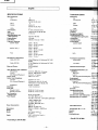
SPECIFICATIONS
SemÈcondustors:
tc,s
Transisto
rs
FET'S
Diodes
LED'S
Track
System:
Tape:
Tape Speed:
Recording
SYstem
and
Bias Frequency:
Erasing Sytem:
Erase
Ratio:
Frequency
Response:
UD-ER
(NOR)
UD-EX
(CrO,
)
FeCr
S/N
(Signal
to Noise
Ratiol:
Dolby
NR
OFF:
Dolby NR
ON:
Wow
and Flutter:
lnput Sensitivity and
lmpedance:
Microphone:
Line in:
Power
Consumption:
Dimensions:
Weight:
Motor:
Heads:
*
According to
DIN
45 500
8
s6
(u,
c)
54
(W,
FS,
BS, AU)
2
4s
(u,
c)
44
(W,
FS, BS,
AiJ}
11
4
track
2
channel
stereo
Cassette tape
(C-30,
60,
901
4.75
cmls
AC bias,
105
kHz
AC erase
65 dB or more
(at
1
kHz)
20 Hz
-
18 kHz
30 Hz
-
17
kHz
(r3
dB)
30Hz-17kHz*
20 Hz
-
20 kHz
30 Hz
-
18 kHz
(t3
dB)
30Hz-18kHz*
20 Hz
-
18
kHz
30 Hz
-
17
kHz
(t3
dBl
30Hz-'lTkHz*
59 dB
(Weighted
A, Reference
3% THD)
59 dB*
67 dB
(Weighted
A, Reference
3%
THD)
67 dB+
0.03%
(wRMS)
O,1"/o
*
0.35 mV,
300 ohms
-
5
kohms.
50
mV, 100k
ohms or more
50 kohms
or more
50
kohms
or more
(U,
C, AU)
470 kohms
or more
(W,
BS,
FS)
Sohms-2kohms
1.3%
(1
kHz
OVU)
60 dB
(at
1
kHz)
or more
30 dB
(at
1
kHz)
or more
90
sec
(using
C-60)
AC 12OV,60Hz
(U,
C)
AC 1
00-1
1
0V
I
1 1
5-127V
1200-220V 1230
-2s0V,
50/60H2
(W)
AC22OV,50Hz
(FS)
AC 24OV,SOHz
(BS,
AU
)
30w
(u,
c)
28W
(W,
FS,
BS,
AU)
165(H) x
435(W)
x
256(D)mm
7.7 kg
Uni-Torque
motor
x 1
DC motor
xl
R
&
P combination
head
x
Erase
head x
1
Technische
Daten:
Bestúckung:
lCs
Transistoren
FET
Dioden
LED
Spursystem:
Tonband:
Bandgeschwindigkeit:
Aufnahmesystem und
Vormagnetisierungsf requenz
:
Lóschsystem:
Lcischdàmpfung:
Frequenzgang:
UD-ER
(NOR}
UD-EX
(CrO,
)
Fremdspannungsabstand :
ohne
Dolby:
mit Dolby:
Gleichlauf
schwankungen
:
E ingangsempf
indl ichkeit u nd
lmpedanz:
Mikrofon:
D I N
(Auf
nahme/Wiedergabel
:
Kopfhòrer:
Klirrgrad:
Ubersprechdàmpfung:
Zwischen Spuren:
Zwischen
Kanàlen:
Schnellvorlauf-
oder Rúcklaufzeit:
Netzspannung und
-frequenz:
Leistungsaufnahme:
AbmessungenlBxHxTl:
I
56
(U,
C)
54
W,
FS,
2
4s
(u.
cl
44
W,
FS,
t1
Cassetten-
4,75
>65
dB
20-'18.000
30-17.O00
30-1 7.000
20-20.000
30-18.000
30-18,000
20-18.000
30-1
7.000
30-1
7.000
59 dB
0,35
mV,
50
mV,
1
DIN
(Aufnahme/Wiedergabe):
0,35
mV,
)550 mV
>50 k
59 dB*
67
dB
67
dB*
o,o3%
o,1Yo',
>50
>470
8 Ohm bis
1,3%
(1
k
>60
dB
>30 dB
90 sek.
120V.60
100-11
230-250V
220V,50
240V.
30w
(u,
cl
28W
(W,
F
165 x 435
7,7
kg
Uni-T
Au
DIN
(Record/Playbackl:
0.35
mV,4.7
kohms
Output
Level:
550
mV
or more
Output Load
lmpedance:
Line
out:
DIN
(Record/Playback)
:
Headphone:
Distortion:
Cross
Talk:
Between
tracks:
Betw€en channels:
Fast Forward or
Rewind
Time:
Power
Supply:
-J-
*
Gemà3
DIN
45
500
Lòschkopf

8
s6
(u,
c)
54
W,
FS,
BS,
AUI
2
4s
(u,
c)
44
O,
FS,
BS,
AU)
1'.|
Viertelspurgeràt,
Stereo
Casetten-Tonband
(C-30,
60, 901
4,75 cm/sek
Wechselstrom-Vormagnetisierung,
1
05
kHz
Wechselstrom
-Lóschung
>65
dB
(bei
1 kHz)
20-18.0O0
Hz
30-17.000
Hz
(r3
dBl
30-17.0O0
Hz
+
20-2O.000
Hz
30-18.000
Hz
(t3
dB)
30-18.000
Hz
*
20-18.000
Hz
30-17.0OO
Hz
(t3
dB)
30-17.000
Hz
+
59
dB
(Bewertungs-f
ilter A,37o
Klirr)
59
dB*
67
dB
(Bewertungs-filter
A,3% Klirr)
67 dB*
0.03%
(wRMS)
O,1Y"
*
0,35
mV, 3O0 Ohm
bis
5
kOhm
50
mV, 100 kOhm oder
mehr
re): 0,35
mV,4,7
kOhm
)550
mV
>50 kOhm
rel:
)50
kOhm
(U,
C,
AU)
à470
kOhm
(W,
BS, FS)
È
Otrm uis
2
kOhm
1,37o
(1
kHz,
0
VU)
>60d8
(bei
l kHz)
>30dB
(bei
1 kHz)
it:
90
sek.
(Casette
C-60)
120V,60
Hz
(U,
C)
1 oo-1
10v/1
1
5
-'127V
1200-220v
I
23O-25Ov
,50/60H2
(W)
22OV
,50
Hz
(FS)
24OY,.SOHz
(BS,
AU)
30w
(u,
c)
28W
(W,
FS, BS, AU}
î65x435x256mm
7,7 ks
Uni-Torque-Motor
x 1, Gleichstrommotor
Autsprech
/Wiedergabekopf
x
1
Lóschkopf
x 1
30 Hz à
17
kHz
(t3
dB)
30Hzà17kHz*
Rapport
S/B
(signal
sur
bruitl:
Dolby NR sur OFF: 59
dB
(Pondérée
A, D.H.T. 3%
59
dB*
SPECI FICATIONS
TECHNI.OUES
Sem
iconducteurs:
cl
Transisto
rs
FET
Diodes
Système de
piste:
Bande:
Vitesse de
défilement:
Système d'enTegastrement
et
fróquence de
polarisation:
Système d'effacement:
Rapport d'effacement:
Réponse
en fréquence:
UD-ER
(NOR)
UD-EX
(CrO,
)
FeCr
Dolby
NR sur ON:
Pleurage et scintillement:
Sensibilité d'entrée
at
impédance:
Microphone:
Entrée
de
ligne:
DIN
(enregistrement/
lectu
re
)
:
Niveau
de
sortie:
lmpédance
de
charge de
sortae:
Sortie
de ligne:
Casque
d'écoute:
Distorsion:
Diaphonig:
Entre
pistes:
Entre canaux:
Durée d'avance
rapkle ou de
rembobinage:
Alimentatíon:
Consommation
ólectrique:
Dimensions:
Poids:
Moteur:
T6tes magnétiques:
*
Conformément aux normes DlN45
500
44
{W,
FS, BS,
AU}
Diodesélectroluminiscentes
11
s
s6
(u,
cl
il
(W,
FS, BS, AU}
2
45
(U,
C)
4
pistes,
2 canaux
Bande
en cassette
(C-30,60,90)
4,75
cm/sec
Polarisation
par
courant alternatif,
105 kHz
Effacement
par
courant alternatif
65
dB
ou
plus
(à
1 kHz)
20
Hz
à
18
kHz
30 Hz à
17 kHz
(t3
dB)
30
Hz à
'17
kHz
*
20 Hz
à2O
k4z
30 Hz à
18 kHz
(t3
dB)
30Hzà18kHz*
20 Hz à
18 kHz
67
dB
(Pondérée
A, D.H.T. 37o)
67
dB*
O,O3%
(WRMS}
o,1%
*
0,35 mV, 300
ohms
-
SK-ohms
50
mV,
1OOKohms ou
plus
0,35
mV, 4,7Kohms
550
mV ou
plus
50K-ohms
ou
plus
47OK-ohms
ou
Plus
(W,
BS,
FS)
8
ohms
à
2K-ohms
1,37o
(lkHz
0VU)
60 dB
(à
1 kHz) ou
plus
30 dB
(à
1 kHz) ou
plus
90
secondes
(avec
une cassette
C-60)
Secteur
120V,60H2
(U,
C)
Secteur
1 00-1
1
0V/1
1 5
-127v
l2OO-22Ov l23O
-25Ov,50/60H2
(W)
Secîeur
220V,
50Hz
(FSl
Secteur
24OY,5OHz
(BS,
AU)
30w
(u,
cl
28W
(W,
FS, BS.
AU}
165(H)x
435(L) x
256(P)mm
7,7
kg
Moteur à couple unique
x
1
Moteur
à
courant continu x 1
TétecombinéeR&Px1
Téte d'effacement x
'l
4"ì
!l'
l
l
I
''t
)
1
1
.l
I
I
1
ì
l
I
1
I
I
l
l
,
j
!
I
I
I
i
I
I
ì
I
I
i
I
l
DIN
(enregistrement/lecture):
50K-ohms
ou
plus
(U,
C.
AU)
x1
-4-

English
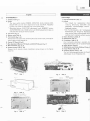
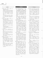
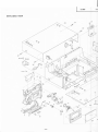
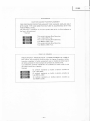
DISASSEMBLY
1.
Cassette
lid
(Fig.
1)
2. Knobs
*
The
lever switch
knobs
(POWER,
MONITOR,
BIAS, EOUALIZER,
DOLBY-NR)
and
the level adjustments
knobs
(OUTPUT,
RECORD
LEVEL) are
pulled
off
from
the f
ront
of the front
panel.
*
Operating buttons, BIAS
FINE
adjustment knob,
MEMORY button,
AUTO-REWIND
knob,
DCCS
button and DCCS adjustment knobs are
removed
after taking
off the
front
panel.
3. Top cover
(Fig.
2)
4. Bottom
cover (Fig.
3)
5.
Front
panel
(Fig.4,
5)
Remove
the front
panel
after
removing the lever switch knobs, level adjust-
ment
knobs
and
the cassette
lid.
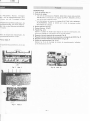
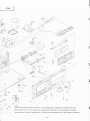
6. Gontrol
PC
Board
(Fig.6l
7.
Bias
adjustment/Memory
PC
Board
and DCCS PC
Board
(Fig.
7l
8. Main
PC Board
(Figs.
8,
9l
9. Cassette
chassis
(Figs.3,
101
Remove the
5 cassette
chassis
installation screws
shown
in the
figures
3 and 10.
Demontage
î.
Cassettenfachdeckel
(Abb.
1)
2. Knépfe
*
D
ie Knòpfe
der
Hebelschalter
(Netzr
tisierung, Entzerrung, Dolby-NR) und
gangspegel,
Aufnahmepegel) kónnen
abgezogen
werden.
*
Die Funktionstasten,
der
Vormagnetir
Speichertaste,
der
Knopf fúr
Riicklaufar
taste
und der
Dolby-Kalibrierregler
sind
rr
nachdem
die
Frontplatte
entfirnt
wurde.
3. Obere Abdeckung
(Abb.
2)
4. Bodenplatte
(Abb.
3)
5.
Frontplatte
(Abb.
4,
5)
Die
Frontplatte
abnehmen, nachdem die
Pegeleinstellknópfe
und
der
Cassettenfachdr
6. Regler-Platine
(Abb.
6)
7.
Schaltplatine und Dolby-Kalibrier-Platine
(l
8.
Haupt-Platine
(Abb.
8,
9)
9.
Cassetten-Chassis
(Abb.
3, 101
Die
fúnf
Befestigungsschrauben
des
Cassett
Abbildungen
3
und
10
gezeigt
sind.
,-\
^
Fig. 1
ll4
0
Abb.
1
Fis.2 Abb. 2
BT3X l0
(with
lock
washer)
(installing
the cassette
chassis)
-A-
ì?
F3X6
BT3XI2
L_-
-È*r.
Fis. 5 Abb.5
-5-
Fig.6
Abb.6

rer
(Netzschalter,
Monitor,
Vormagne-
NR)
und die
Pegeleinstellknòpfe
(Aus-
kónnen
von der
Frontplatte
einfach
)rmagnetisierungs-Feineinstellknopf,
die
ìúcklaufautomatik,
die
Dolby-Kalibrier-
gler
sind
von
der
Rùckseite
abzunehmen,
nt
wufde.
ldem
die
Knòpfe
der
Hebelschalter,
die
ft enfachdeckel
entfernt
wurden.
-Platine (Abb.
7)
es
Cassetten-Chassis
entfernen,
die
in den
DEMONTAGE
1. Volet
de cassette
(Fig.
1l
2.
Boutons
de réglage
*
Les
clefs de commutation
(POWER,
MONITOR,
BIAS,
EOUALIZER,
DOLBY-NR)
et les
boutons
de
réglage
(OUTPUT,
RECOBD
LEVEL)
sont retirés
par
le
panneau
avant.
*
Les
interrupteurs
et
boutons
de
réglages
BIAS FINE
ADJ,
MEMORy,
AUTo-REWIND.
Dccs
et
Dccs
sont
retirés
du
panneau
arrière
après
dépose
de la fagade.
3. Plaque supérieure
(Fig.
2)
4. Plaque
inférieure
(Fig.
3)
5. Fagade
(Fig.4,5l
Déposer la
plaque
de facade
après
dépose des
clefs de commutation,
des
boutons de réglages et
interrupteurs
et du volet de
cassette.
6.
Plaquette
à circuits imprimés
de commande
(Fig.
6l
7. Plaquette
à circuits imprimés
de
commutation et
plaquette
de
DCCS
(Fig.
7)
8.
Plaquette
à
circuits imprimés
d'alimentation
(FiS.
8,
gl
9.
Chàssis
de magnétocassette
(Fig.
3, 10)
Dévisser les 5 vis
de montage
de chàssis
de
magnétocassette
indiquées
sur
les
illustrations 3 et
10.
B3X 8
(btack)
Fis.
10 Abb.
10
Fis.
8
Abb.8
-6-

F
E
o
IJ
È.
o
o
lr'
o
o
-o
o
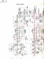
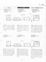
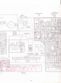
BLOCK
DIAGRAM
I
--J
lrj
z
I
À
ó
oul
-I
É-
J
o
9
ct
E
U
B
J
)
{o
OE
__l-
ao<
iis
eBa
ONÎ
.l
P
z
o
=
z
cl
@
o
F
l
o
=
o
o-
ìrH
o>>
roP
ÀÀ;
3:
OU
.l
ul
F
ou
E;
<o
ÎL
o..
=5
l!
É
3q
;)
É.
eÈ
F<
ifi
NF
E
o
t
o
U
oo
6A
f
o
o
oo9
_r=
,
!tó
-NF
Àeà
F
l
o
olu
8E
9d
oo
F<
U
T
6
!
6
F
o
I
o
N
o
I
Et-
Jf
oÀ
ÒF
-f
>o
e
ú.-6
J
t
d
,gÈi
-àl
d1
(D
J
o
o
fT
I
+-
o
t!
(l
o
<F
ftt
ON
=9
t.É|
JJ
-N
oo
L
L
o
o
)
o
ó
-*3*
qgg
ONJ
i9*
eÍq
jg*
;R"
tr
o
a.d
JUì
ó3
o
N
aQ
9jg
=U
E=
9<
lrj
J
É.
eZ
iur
óz
2l
t'-
o
of
o=
No
o
!
o
I
a0
o
N
I
o
!
o
@
o
I
6
@
I
o
t!
FI
@l
!
HU
o
f
o.
ú,
j
8
a
o-16
c
=f
z
s
--
o
-
g
:EE
OO!-
;Sí
(x
o
NO.
60
'>
%3
-7-

à9
pq
È.
P
9
o
z
Y
IJ
o-
Level
values
shown
in th€ diagram are
the
playback
output levels obtained by
play
ing back
a tost tapo MTT-I50.
Recording input
levels are
sot at eacl
input terminal
so that
playbsck
output
levels
using
the t€3t tape MTT-150 can
be
obtained.
6
È
.
o
Èr
sd
i.
F^
"d3
ÌHfi
fieE
E
o
o
z
U
J
o
a
ul
Y
È
@
9E
:9
Eb5
638
Q
-()
o9
FF
r
9È
.,8
R$H
aiÉ
uF
o
---+
o
z
ì
U
I
o
F
f
3g
;
;ù;
@
+
OF
-f
oo
F
f
o
eE
o(J
iro
-z
sÉ
oì
Èa
=
.lt
o
U
t!
È
s6
Eg
d=
>-i
u-
ÉH
fc
ls
sÈ
z
o
F
o
ur
fl
FO
r!F
o()
o-
u'i
9ú
E;A
9H
\o
a=
^ó
6R
ui
!
o
o
I
n
('
o
F<
rF
o
=5
<o
ÈHE;
9
N
ó
o
N
qP
6F
ò;o
6NÈ
Nrl
ÉÉs
88s
l!
ft
ۃr
o
ììÈ
o
ù
-8-

a
English
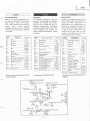
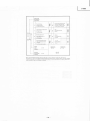
ADJUSTMENTS
Perform the
following
adjustments
in
the sequence
stated
after cleaning
the
head,
pressure
roller,
and
capstan
with
a
head cleaning
stick
moisted
in
alcohol.
Also,
unless
sPeciallY
indicated
otherwise,
set the
switches
and
controls
to
the
positions
indicated
in the table.
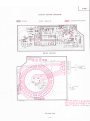
Adjustment
and
semi-conductor
paÉs
location
diagram
Abgleiche
Die folgenden Abgleiche
in
der auf-
gefùhrten
Reinhenfolge
durchfÚhren,
nachdem
die Tonkópfe,
die
Andruck-
rolle
und die Tonwelle
mit einem
in
Alkohol angefeuchteten
Reinigungs-
stàbchen
gereinigt
wurden.
Wenn nicht
anders angegeben,
die Schalter
und
Regler
gemàB
nachfolgender
Tabelle
e
instellen.
Symbol
Nr.
Schalter
oder
Regler
Position
S1 Netzschalter
ON
s2
Dolby-NR
OFF
S3
Moniîor
TAPE
S4
Vormagnetisieru
ng
UD-ER
(NOR)
S5
Entzerru ng
UD-ER
(NOR}
S6
D olby
-Kalibrieru
ng
OFF
s12
A usgan
gssc
h
al
te r
(W,
BS,
FS)
OFF
sl4
Speicher
OFF
RVl Aufnahmepege
(M
lClD
lN
)
Max.
BV2
Aufnahmepege
(LINE)
Max.
RV4 Dolby-Kalibrieru
ngs-
Aufnahmepegel
Mittel-
stel
I u ng
RV5 Vormagnetisieru
ngs-
Feineinstell
knopf
Mitîel-
stellung
RV1
OO
Ausgangspegel
Max.
Anordnung
der
Einstellelemente
RTIR
-TPIL
Dol by
(recording)
odjustmenl
REGLAGES
Procéder
aux
réglages
suivants
et
dans
l'ordre
spécifié
après
avoir
nettoyé la
surfacc
des
tétes
magnétiques,
du
galet-presseur
et le cabestan
avec
un
bàtonnet
de nettoyage
à embout
de
coton
imbibé
d'alcool.
Par
ailleurs,
et
à
moins
qu'une
sPécif
ication
Par-
ticulière
ne
soit
faite,
régler
les com-
mandes
et interrupteurs
sur les
posi-
tions
spécifiées
dans le
tableau'
Emplacement
des
semiconducteu
rs et
Réglage
Symbol
No.
Switches
and
controls
Position
S1
Power
ON
S2
Dolby
NR
OFF
S3 Mon iîor
TAPE
S4
Equal izer
UD-ER
(NOR)
S5 Bias
UD-ER
(NOR)
S6
DCCS
OFF
s12 D I
N
ouîput
(W.
BS.
FS onlv)
OFF
s14
Memory
OFF
RV1
Record level
(MlC/DlN)
MAX
RV2 Record level
(LINE)
MAX
RV4
DCCS
Record level Center
position
RV5 Bias
fi ne
Center
position
RVl OO Output
level
MAX
No de
symbole
I nterrupteurs
et
commandes
Position
S1
I nterrupteur
général
ON
s2
Dolby
NR OFF
s3
Contr6le
TAPE
S4
Egal iseu
r
UD-ER
(NOR)
S5
Polarisation
UD-ER
(NOR}
S6
DCCS
OFF
s12
Commutateur
de
sortie
(W,
BS,
FS)
OFF
s14
Mémoire
OFF
RV1 Niveau
d'enregis-
trement
(MlC/DlN)
MAX
RV2
Niveau
d'enregis-
trement
(LINE)
MAX
RV4 Niveau d'enregis-
trement DCCS
Position
central
e
RV6
Régleur
Fin
de
polari-
sation
Position
cen tral
e
RVlOO
Niveau de sortie MAX
-9-

I
Engtish
I
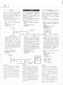
Next,
connect
the indicated signal
source and measuring
instruments as
shown in the connection
diagram for
each adjustment;
then
perform
the
adjustment
as described.
The adjustment
parts
are
shown in the
diagram on the
previous page.
1.
Tape speed
(motor
speed)
adjust-
ment
Setting: Playback
mode
Connection:
MTT-111
3000H2(31 50Hz*
Adjustment:
Warm up
the unit
for
approxiryately 20 minutes; then
playback
test
tape MTT-'l 1 1,
3000H2(3150H2*), and measure
the speed deviation
with a frequen-
cy counter. lf required,
adjust the
semi-variable resistor
on the motor
for
a reading
of 3000H2(3150H2*).
Carry
out the
measurement
at the
middle
of the tape.
Head azimuth
adiustment
Setting:
Playback mode
Connection:
MTT-'I14
10 kHz
Adjustment:
Use the
H ITACH
I head adjusting
jiS
and
instructions.
(Consult
nearest
H ITACH
I
office.)
To obtain the
correct
head
height,
tilt
and azimuth.
This adjustment
has
to
be done alternately.
Then,
use
test
tape
(MTT-114,
10 kHzl
to adjust
the azimuth
of Record/
Playback
head by means
of
the
adjusting
screw
"a"
for
maximum
output.
Danach
die
angegebenen
Signalquellen
und
MeBinstrumente
gemàB
der
Diagramme
fúr die
einzelnen
Ein-
stellungen
anschlieRen und die Ein-
stell
ungen
durchfùhren.
Die Einstellteile
sind dem Diagramm
auf
der
vorhergehenden
Seite
zu
entnehmen.
1. Bandgeschwindigkeit
(Motordreh-
zahl)
Einstellung:
Wiedergabe
Anschlússe:
Brancher
ensuite la
source
de
signal
re-
commandée et les
appareils de
mesures
comme indiqué
sur le
schéma de
branchement
et réaliser les
réglages
comme décrit.
Les
organes
à
régler
sont
indiqués
sur
le schéma de
la
page
précédente.
1. Réglage
de
vitesse
de
défilementde
bande
(Vitesse
de rotation
du
moteur)
Béglage: Mode
de
lecture
Branchement:
*
According to
DtN
45 500.
Régiage:
Laisser chauffer
l'appareil
pendant
environ
20
minutes
puis
lire une bande
de contròle
MTT-
1 1 1,
3000H2(3150H2*)
et
mesurer
l'écart
de vitesse avec
un compteur
de fréquence.
Au
besoin, ajuster
la
résistance
semi-variable
du moteur
pour
obtenir
une
indication de
3000H2(3150H2*).
Effectuer
les
mesures
en milieu
de bande.
2. Réglage
d'azimuth de téte
magné-
tique
Réglage:
Mode de
lecture
Branchement:
Top view
of
Record/Playback
head
Réglage:
Utiliser
le
gabarit
de réglage
de téte
H
ITACH I et lire
les instructions
(consulter
le service
H ITACH
I
le
plus proche
de chez vous).
Pour
obtenir un réglage
précis
de
la
hauteur
de téte, l'inclinaison
et
l'azimuth,
ce
réglage
doit étre
fait
alternativement.
Ensuite,
utiliser une bande de
con-
trÒle
(MTT-114,
10kHz)
pour
ajuster l'azimuth de la téte
combi-
ngee enregistrement/lecture
en
utilisant la vis
"a"
pour
obtenir
un
niveau de sortie
maximum.
2.
Abgleich: Das Geràt fiir etwa 20
Minuten
warmlaufen lassen;
danach
das Prúfband
MTT- 1 1 1,
3.000
Hz
(3150H2*)
abspielen und
die Ges-
chwindigkeitsabweichung
mit
ein-
em
Frequenzzàhler
messen. Wenn
erforderlich,
den Regelwiderstand
am
Motor
nachjustieren,
bis der
Frequenzzàhler
3.000H2(31
50Hz*)
anzeigt.
Die
Messung in der Mitte
des
Tonbandes
vornehmen.
2. Tonkopfazimut
Einstellung:
Wiedergabe
Anschlússe:
Abgleich:
Die H ITACH
I
-Tonkopf-Einstellehre
verwenden
(wenden
Sie sich
an die
nàchste
HITACHI-Vertretung)
. Um
richtige
Tonkopfhóne,
Tonkopgnei-
gung
und
Azimuteinstellung
zu
erhalten,
muB
dieser
Abgleich
eini-
ge
Male
wiederholt
werden.
Danach
das
Prùfband
(MTT-
1 1 4,
10
kHz)
abspielen und
den Aufs-
prech-/
Wiedergabekopfazimut
mit
Hilfe
der
Schraube
"a"
einstellen,
bis
maximaler Ausgangspegel
ge-
wàhrleistet ist.
-
10
-

English
3.
Source
monitor
level adiustment
Setting:
Playback
mode
Connection:
3'
Monitorpegel
(Vorbandkontrollel
E instellung:
Wiedergabe
Anschlibse:
D-980
3.
Réglage
de niveau
de contr6le
de
soufce
Réglage:
Mode de lecture
Branchement:
Adjustment: Feed
a
400 Hz signal
into LINE
lN.
Adjust the
Record
level
control or the
signal
generator
so that output
voltage at TPl
L, R
is
0.775V.
Then, set the
Monitor
switch
to SOURCE and
adjust
RT2(L, R) so that output
voltage
at TP3L,
R is
0.775V.
Abgleich:
Ein
400 Hz
Signal an den
LINE lN
Buchsen
einspeisen.
Den
Aufnahmepegelregler
oder
den
Si-
gnalgenerator
einstellen.
bis eine
Ausgangsspannung
von
O,775Y an
TPl
L, R anliegt.
Danach
den Moni-
torschalter
auf Position
SOU
RCE
stellen
und
RT2(L, R) einstellen,
bis
die
Ausgangsspannung
an TP3L,
R
0,775V
betràst.
Réglage: Appliquer
un
signal
de
400H2
à
l'entrée de ligne LINE lN.
Ajuster
le
bouton de niveau
d'en-
registrement sur
le
générateur
de
signaux
pour
obtenir
une
tension
de
sortie
de
0,775V aux broches
TPl
L, R. Ensuite,
régler la clef
de contróle
su r
la
position
SOURCE
et
ajuster RT2(L, R)
pour
obtenir
une
tension de sortie
de
O,775V
aux
broches TP3L, R.
VTVM
TPl
L, R
SG
LINE lN
ja<
ks
D-980
VTVM
Attenuator
{
l
-
11
-

Ir
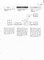
4.
Playback
output and
VU
meters
adjustment
Setting:
Playback mode
Connection:
4. Wiedergabepegel
und
Pegelmesser
Einstellung:
Wiedergabe
Anschlússe:
4.
Réglage de niveau de sortie
de
lecture et d'indicateurs de niveau
Réglage:
Mode de
lecture
Branchement:
Abgleich:
1) Monitorschalter auf
Position
SOURCE stellen.
Ein
400 Hz
Signal an
den LINE
lN
Buchsen
einspeisen und
den
Signalge-
nerator einstellen,
bis an
den
Stiften
TP3 L,
R
eine Ausgang-
sspannung von 0,775V
anliegt.
2) Danach RT103(L,R)
einstellen,
so daR die
Anzeigenadeln
der
lnstrumente bis zue Dolby-Mar-
kierung
(f[
)
ausschlagen.
3) Danach
den Monitorschalter
auf
Position TAPE
stellen.
Ein
Priif-
band
(MTT-150,
400 Hz, 20m
Maxwell)
abspielen
und RT1d0
(L,R)
einstellen, so
daB die
Anzeigenadeln
der lnstrumente
bis
zur Dolby-Markierung
(
)f
)
au ssch
lagen.
Réglage:
1) Régler
la clef
de contrÒle
sur la
position
SOU
RCE. Appliquer
une
signal
de 400H2
à l'entrée
de
ligne
LIN
E
lN
et
ajuster
le
générateur de
signaux
Pour
obtenir
unè
tension
de sortie
de
O,775V
aux
broches
TP3L, R.
2)
Aiuster
ensuite RT103(L,R)
pour
que
les
aiguilles
d'indicateurs
viennent
se
placer
sur
le sYmbole
(DC
I
ootuv.
3)
Régler
la
clef de
contrÒle
sur la
position
TAPE.
Lire
une bande
de
contròle
(MTT-150,
400H2
20m
Maxwell)
et
ajuster RT100
(L,R)
pour
que
les aiguilles
d'indicateurs
viennent
se
Placer
en
face
du symbole
(
DC
)
DolbY.
TP3L,
R
SG
LINE
lN
jacks
VTVM
Attenuator
D-980
MTT.150
400H2,
20m
Maxwell
Adjustment:
'l
)
Set
the
Monitor switch to the
SOU RCE
position.
Feed
a
4OOHz
signal
into
LINE lN
and
adjust the signal
generator
so that
output
voltage
at TP3 L, R
is
0.775V.
2)
Then, adjust
RT103(L,R)
so
that
the meter indicators
def lect to the
Dolby
marks
(
DC
).
3) Set
the
Monitor switch to the
TAPE
position.
Playback
test
tape
(MTT-150,40OHz
2Om
Maxwell) and adjust RT100(L,R)
so that the
meter
indicators
def lect
to
the
Dolby marks
(Df
).
-12-

English
5.
Bias current, record
level adjust-
ment
Setting:
Record
ing/Playback
mode
Gonnection:
5.
Vormagnetisierungsstrom,
Aufnah-
mepegel
Einstellung:
Aufnahme/Wiedergabe
Anschlússe:
LINE
lN
jacks
Abgleich:
1) HITACHI UD-ER
C-90 Cassette
verwenden.
2)
Den
Monitor-Schalter auf
Posi-
tion
SOURCE
stellen und
ein
4OO Hz
Signal an den
LINE lN
Buchsen
einspeisen.
Danach das
Dàmpfungsglied
des
Signalgenerators so abgleichen,
daB die VU-Meter des Geràtes
einen Pegel
von O
VU anzeigen.
AnschlieBend den
Monitor-
Schalter auf
Position TAPE
stellen und
RV4
(L,
R
-
DCCS)
so abgleichen, daB
die VU-
Meter
einen
Pegel
von O
VU
anzergen.
3) Den
Monitor-Schalter auf
Po-
sition
SOURCE stellen,
ein 1,2
kHz
Signal
an den
LINE lN
Buchsen
einspeisen
und das
Dàmpfungsglied
des
Signal-
generators
so einstellen,
daB
die VU-Meter
einen
Pegel von O
VU anzeigen. Die
Anzeige
des
Róhrenvoltmeters
beachten
(diese
Anzeige ist
der
Standard-
Aufsprechpegel:
A
dB).
4)
Den
Monitor-schalter auf
Position
TAPE stellen
und RT5
(L,
R) so abgleichen,
daB das
Róhrenvoltmerér
-1
dB
ge-
genùber
dem Maximalwert
anzei-
gt.
5.
Réglage de niveau
d'enregistrement
et de courant
de
polarisation
Réglage:
Mode d'enregistrement/
lectu
re
Branchement:
LINE OUT
iacks
Réglage:
1) Utiliser
une
bande
HITACHI
UD-ER
C.90.
2)
Régler
l'interrupteur de
contrÒle
sur
la
position
SOURCE. Ap-
pliquer
un signal de 400H2 à
la borne LINE
lN et ajuster
l'atténuateur
du
générateur
de
signal
pour que
les
VU-mètres
indiquent 0
VU.
Régler
ensuite l'interrupteur de
contròie sur
la
position
TAPE
et ajuster RV4
(L.R
DCCS)
pour
que
les
VU-mètres indi-
quent
0
VU.
3)
Régler
l'interrupteur de contròle
sur
la
position
SOURCE
et
appliquer
un signal de 1,2k1z
à
la borne LINE lN
et
ajuster
I'atténuateur
du
générateur
de
signal
pour
que
les VU-mètres
indiquent 0
VU.
Observer
le
voltmètre électronique
(l'indica-
tion
obtenue
correspond au ni-
veau normal
d'enregistrement
A
dB).
4) Régler
I'interrupteur
de contròle
sur
la
position
TAPE
et ajuster
RTs
(L,R)
pour
que
le volt-
mètre
électronique
indique
-1dB
à
partir
de l'indication
maximale.
Adjustment:
1) Use
HITACHI
UD-ER
C-90
tape.
2)
Set
the monitor switch to
the
SOU
RCE
position
and
feed
400H2 signal
into LINE lN
and adjust the attenuator of
the
signal
generator
so that the VU
meters
of
the set indicate
OVU.
Then,
set
the
monitor switch to
TAPE
position
and adiust RV4
(L,R-DCCS)
so that the VU
meters indicate OVU.
3) Set the monitor switch
to
SOU RCE
position
and
feed
1.2kHz signal
into
the
LINE lN
and adjust the attenuator of the
signal
generator
so
that the VU
meters indlcate OVU.
Observe
VTVM
(This
indication
is the
standard
recording level:
A dB).
4)
Set the monitor switch to TAPE
position
and
adjust RT5(L, R
)
so that
the VTVM indicates
-1dB
from the
maximum lndi-
cation.
MAXIMUM
F
f,
o-
F
l
o
-
-t--
-1dB
VTVM
SG
I+oonil
Attenuator
D-980
/
-4
{
BIAS CURRENT
-13-

English
5)
Set
the
monitor switch
to
SOURCE
position.
Reduce
the
output
of the
signal
generator
(Adjust
the
attenuator
of the
signal
generator
)
so that
the
VTVM
indicates
-20
dB
from
the
standard
recording
level
A.
Then,
set the
monitor
switch
to TAPE
position
and observe
the VTVM
(This
indication
is
B dB).
6)
Set the
monitor switch to
SOURCE
position.
Feed
12kHz signal into
LINE lN
and adjust the
attenuator of the
signal
generator
so that the
VTVM indicates
-20
dB from
the
standard recording
level A.
Set the monitor switch
to TAPE
position.
Then, ensure that
the VTVM
indicate
Bl1.5dB.
lf
not, readjust
RT5(L,R)
at
this
condition.
7)
Confirm
the adjustment
for
CrO2
tapes
by the
following
ste
ps.
Use H
ITACH I U D-EX C-90 tape.
Set
the equalizer and
bias
switch
to CrO2
position.
Adjust
RT3(L,R)
by
step
(2).
Then,
repeat step
(3)
by
1 kHz
signal and
(5).
8) Set
the monitor
switch
to
SOURCE
position.
Feed 16
kHz signal
into
LINE
lN and
adjust
the attenuator
of
the
signal
generator so that
the
VTVM
indicate
-20
dB
from
the standard
recording
level
A.
Set
the
monitor
switch
to
TAPE
position
and
ensure
that
the
VTVM
indicates
B
11.5
dB.
lf not,
readiust
RT4 at
this
condition.
5)
Den
Monitor-Schalter
auf Posi-
tion
SOURCE
stellen.
Den
Ausgangspegel
des
Signalgenera-
tors
reduzieren
(das
Dàmpfungs-
glied
des
Signalgenerators eins-
tellen),
so
daB das
Róhrenvolt-
meter
-20
dB
gegenùber
dem
Standard-Aufsprechpegel
A
an-
zeigt.
Danach
den Monitor-Schalter
auf Position
TAPE stellen
und
die
Anzeige
des
Róhrenvolt-
meters
beachten
(diese
Anzeige
betràgt
B dB).
6)
Den Monitor-schalter
auf
Pol
sition
SOURCE
stellen, ein 12
kHz
Signal an den LINE
lN
Buchsen
einsepisen
und
das
Dàmpfu
ngsglied
des
Signaigenera-
tors
so
einstellen,
daB
das
Ró_
hrenvoltmerer
-20
dB
gegenúber
dem
Standard-Aufsprechpegel
A
anzeigt.
Danach
den
Monitor-
Schalter
auf
position
TApE
stellen.
Darauf
achten,
da8
das
Róhrenvoltmeter
einen
pegel
von
B
11,5
dB
anzeigt;
wenn
nicht,
RT5
(L,
R)
nochmals
nachj
ust
ieren.
7)
Den
Abgleich
fùr
CrOr-Band
wie folgt
Kontrollieren:
HITACHI
UD-EX
C-90
Cassette
verwenden
und
die
Wahlschalter
fùr
Entzerrung
und
Vorm-
agnetisierung
auf Position
CrO2
stellen.
Danach
RT3(L,R) gemaB
Schritt
(2)
abgleichen.
Anschlie-
Bend
die
Schritte
(3)
mit
einen
1-kHz
Signal
und
(S)
wieder-
holen.
8) Den
Monitor-schalter
auf
posi-
tion
SOURCE
stellen,
ein
16
kHz
Signal
an
den
LINE
lN
Buchsen
einspeisen
und
das
Dàmpfungsglied
des
Signalgener-
ators
so
einstellen,
daB
das
Ròhrenvoltmeter
einen
pegel
von
-20
dB
gegeniiber
dem
Standard-Aufsprechpegel
A
an-
zergt.
Anschlie8end
der Monitor-Schal-
ter
auf
Position
TAPE
stellen
und
darauf
achten,
daB
das
Ròhrenvoltmeter
einen
pegel
von
B
11.5
dB anzeigt.
Wenn
nicht,
RT4
in
diesem
Zustand
nachj
ust
ieren.
5)
Régler
l'interrupteur de
contròle
sur la
position
SOURCE,
dimi-
nuer
la niveau
de sortie du
gé-
nérateur
de signal
(ajuster
I'at-
ténuateur
du
générateur)
pour
que
le
voltmètre
électronique
indique
-20d8
à
partir
du
niveau normal
d'enregistrement
,
A.
Ensuite,
régler
I'interrupteur
de
contròle
sur
la
position
TAPE
et
observer
le voltmètre
élec-
tronique
(Cette
indication
cor-
respond
à
B dB).
6)
negter l'interrupteur
de
contròle
sur la
position
SOURCE
et
appliquer
un
signal
de 12
kHz
à la
borne
LINE lN
et ajuster
l'atténuateur
du
générateur
de
si-
gnal
pour
que
le
voltmètre
électronique
indique
-20d8
à
partir
du niveau
normal
d'enregi-
strement
,A
Régler
l'interrup-
teur
de contròle
sur la
position
TAPE.
Ensuite,
voir
si le
volt-
mètre indique
811,5
dB,
Dans
le
cas contraire,
réjauster
RT5
(L,R
en conséquence.
7)
Confirmer
le réglage
avec des
bandes
CrO2
en
procédant
com
me suit.
Utiliser
une
bande HITACHI
UD-EX C-90.
Régler
l'interrupteurs
de
polari-
sation
et
d'égalisation sur la
position
CrO2. Ajuster RT3
(L,R)
en effectuant l'opération
(2t.
Répéter l'opération
(3)
en
appliquant un signal
de i kHz et
opération
(5).
8)
Régler
l'interrupteur
de contrÒle
sur la
position
SOURCE.
Ap-
pliquer
un
signal
de
16kHz
à
la borne
LINE
lN
et ajuster
I'atténuateur
du
générateur
de
signal
pour
que
le
voltmètre
électronique
indique
-20d8
à
partir
du
niveau
normal
d'enre-
gistrement
A
.
Régler
l'interrup-
teur
de
contrÒle
sur la
posi-
tion
TAPE
et
voir
si le
volt-
mètre électronique
indique
8t1.5 dB.
Dans
le cas
contraire,
réajuster RT4
en conséquence.
1\'
-
\
-14-

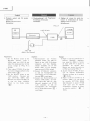
D-980
Adjustment:
Feed
a
5kHz signal
into
LINE lN,
so rhat
the voltage
at
TP2L,
R becomes
-30.4dBm.
Then,
set the DOLBY
NR
Switch
to
oN. Adjust
RT1(L,R)
so that
the voltage
at
TP2L,
R becomes
-22.4d8m.
6.-2
Playback
Setting;
Playback
mode
Connection:
English
6.
Dolby
NR
adjustment
6.-1
Record
Setting: Playback
Mode
Connection:
6.
Dolby-NR-Abgleich
6.-1
Aufnahme
Einstellung:
Wiedergabe
Anschlússe:
LINE lN
jacks
Abgleich:
Ein
5 kHz
Signal an den
LINE lN
Buchsen einspeisen,
so
daB der
Pegel
an TP2L,
R
-30,4
dBm
betràgt.
Danach
den Dolby-
N R-Schalter
auf Position
ON
stellen.
RT1
(L,
R) einstellen,
so
daB
der Pegel
an
TP2L, R
-22,4
dBm betràgt.
6.-2
Wiedergabe
E
instellung:
Wiedergabe
Anschlússe:
TP5L
Abgleich:
Den Monitorschalter
auf
Position
TAPE
stellen
und ein
5kHz
Signal an TPSL, R einspeisen,
so
daB der
Pegel
an TP4L, R
-22,4
dBm
betràgt. Danach den Dolby-
NR-Schalter
auf
Position
ON stellen
und RT101(L,
R)
einstellen, bis der
Pegel
an TP4L. R
-30,4d8m
betràgt.
6.
Réglage
de Dolby
NR
6.-1
Enregistrement
Réglage:
Mode
de
lecture
Branchement:
TP2L,
R
Réglage: Appliquer un
signal de
SkHz aux
prises
d'entrée de ligne
LIN E lN
pour
que
le
niveau de
sortie
aux
broches TP2 L,
R soit
égal
à
-30.4d8m.
Ensuite,
basculer
la clef de commutation
de
Dolby
sur ON. Ajuster RTl(L,
R)
pour
que
le niveau
de sortie
aux
broches
TP2L,
R
soit
égal à
-22AdBm.
6.-2 Lecture
Réglage:
Mode de lecture
Branchement:
Adjustment:
Set the
Monitor
switch
to
the
TAPE
and
feed
5kHz signal into TPSL, R
so that
the
voltage
at TP4L, R becomes
-22Ad8m.
Then, set
the
Dolby
switch to ON, and adjust RT101
(t-,
R
)
so
that the
voltage
at
TP4L, R becomes
-30.4dBm.
Réglage:
Régler la
clef de
contròle
sur
la
position
TAPE
et
appliquer
un
signal
de 5kHz
aux
broches
TPSL.
R
pour
que
le
niveau
de
sortie
aux
broches
TP4L,
R
soit
égal
à
-22,4d8m.
Ensuite,
basculer
la clef
de commutation
de Dolby
sur ON et
ajuster
RT101(L,
R)
pour
que
le
niveau
de
sortie
aux
borches
TP4L,
R
soit égal
à
-30,4d8m.
VTVM
t=;;;7t
I
-zr.o
or^
I
D-980
/
Attenuator
{
TP4L, R
SG
5kHz
VTVM
-22.4
dBm/
-30.4
dBm
D-980
/
Attenuator
{
oÈ-
-15-

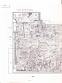
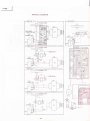
CIRCUIT
BOARD
DIAGRAM
:
Ground
:
Signal,
+B
LEDI02 LEDIOI
PEAK
LEDIOO
INDICATOR
3-HEAD
INDICATOR
-16-

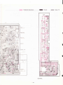
CIRCUIT
BOARD
DIAGRAM
I
f
l'
È.
"l
MAIN
-17
-

:
Component
side
pattern
I
:
Ground :
Signal,
+B
1
t?
a
tsè
a
!-l
1r
RECORO LINE
RECORO MICIDIN
I
I
I
I
I
CONTROL
-18-

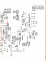
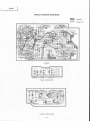
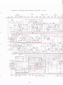
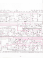
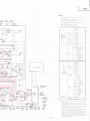
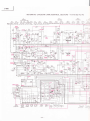
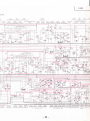
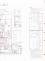
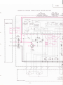
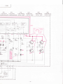
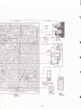
SCHEMATIC
DIAGRAM
(AMP./CONTROL
SECTION)
-
For
U,
C
-À.
Dr3 0r5
06
o2L
2SC|74O
2SC\74O
DCCS
4OOHZ
OSC
Dls
Dl4 Oll4L
Dl24
lClL tC3L
QIL
Hprl6 1s2473 2SK68Aì
FE-g
HAt406 HAr406 2SC458LG
1s2473
?SC!74o
BACK CURRENT
S\fuNCHII\IG
CHECK
l-
-
HEADAMP
VOL]: I\1ICIDIN
HEAD
AMP
N4C/DIN
AMP
-STAB
-
SWITCHING
SWITCHING
LINE AI\1P
SWITCHING
PLAY
DOLBY-NR
,r3l$rn
'P)3orc
LINE
AMP
lr
HI
REC DOI
Qil2
25Ct2r
BIAS COÀ
QtooL orolL Qro2L
25Dil67 250467 2SCt740
oro3L
rc4
2SD467
H4il226
SWITCHING
HEADAMP
fErNl
t---
-
-
6li|lrqî
L'-c--
PLAYBACK
HEAD
I
P
R8l
331(,
D2
D30r
ts?473
swtrcHlNG
tc300
HAt200r
MODE
CONTROL
LED3OO
GL-3P
"PALI6E,,
LED302
03@
ot23L
GL- 3P
tS2473
ts2473
"PLAY'
RE6T RF6T
Q4L
SWITCHING
olooL DrorL
tN34A t52473
RECT RECT
QIO3L
@2
L€CSOI
GL-3P
trL
-19-
D|2,Dt27 D|O, Dl
1s2473
ts247.
SWITCH NG
SWIICH
II

tc?
DrL
D2L
o5L
QrO DrO
Dr I
Di6
0r
r
_- ))
tl2?6
lN34a
ts2473
zscrT4o
2sat74o tsa4ó
ts2473
t{z4zt zstrzqo
ECDOLBY-NR
REcTFoRDoLBYR€crFoRDoLBY
necebarvp
sirìiòrìiruc.r*értc6'.r;p-trÓftcsúr-Éul^ie s'ùircrtrle
or4
otos
0to6
Dto2t_Dro3L
Dto4LD6L
OpZOtOS,Opg
DtO3 LED|OO,
cil62wT 2sct740
2SCt740
tN34A
tN34A
2SCt740
awot_7 GL
_
:
lgosc
J.ErBryB.]NrgA{oRp\MB
REcr
JEcîFoRrNo.
swtrcHtNc_
FOR MFTFR
--1
05
F*
Drr
(Rch
RSR 2-7K )
'*'rtlt
rr?,|,f;o
oi{1'3}'u"
D2l4D2l5
e2o6
ozos
o2ro
e2t?
LEor LED2 LED3 LED4
LEDo
.Q?Qg-
D?oQ Dr
e?t?
o?t
rcHtN6
svilÌcHtNc
swtrcHtNc
pRorEcroR
€!D4688
2sp46aBv2sq59_Asel?.!Ee,
Gl-3ps_-3pcL-3p
e-3p
G_-3p
2scil62
Hz-rs ts24zs tS2473
Vo€
swtTcHtNG FoR
REW
rnar"soncrunpur"REc
rn-ay"
qvoLT
PRotEcloR-
swiìtHil
-20 -
Seite wird geladen ...
Seite wird geladen ...
Seite wird geladen ...
Seite wird geladen ...
Seite wird geladen ...
Seite wird geladen ...
Seite wird geladen ...
Seite wird geladen ...
Seite wird geladen ...
Seite wird geladen ...
Seite wird geladen ...
Seite wird geladen ...
Seite wird geladen ...
Seite wird geladen ...
Seite wird geladen ...
Seite wird geladen ...
Seite wird geladen ...
Seite wird geladen ...
-
 1
1
-
 2
2
-
 3
3
-
 4
4
-
 5
5
-
 6
6
-
 7
7
-
 8
8
-
 9
9
-
 10
10
-
 11
11
-
 12
12
-
 13
13
-
 14
14
-
 15
15
-
 16
16
-
 17
17
-
 18
18
-
 19
19
-
 20
20
-
 21
21
-
 22
22
-
 23
23
-
 24
24
-
 25
25
-
 26
26
-
 27
27
-
 28
28
-
 29
29
-
 30
30
-
 31
31
-
 32
32
-
 33
33
-
 34
34
-
 35
35
-
 36
36
-
 37
37
-
 38
38


in anderen Sprachen
- English: Hitachi D-980U User manual
- français: Hitachi D-980U Manuel utilisateur
Verwandte Artikel
Andere Dokumente
-
Hama 00005201 Bedienungsanleitung
-
Dometic RainTec RT100 Installationsanleitung
-
Denon DRM-550 Operating Instructions Manual
-
Aiwa AD-F 800U Bedienungsanleitung
-
JVC KD-A55 Bedienungsanleitung
-
-
-
-
Sharp CD-DD4500 Benutzerhandbuch
-
Liebherr KSV4220DF Bedienungsanleitung