MAC Audio 520 DAB Installationsanleitung
- Kategorie
- Auto-Video-Systeme
- Typ
- Installationsanleitung
Dieses Handbuch eignet sich auch für

MAC 520 DAB
Installationsanleitung
Installation Guide

3
6
9
Anschlussdiagramm/
Wiring Diagram

3
3
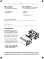
Lieferumfang Benötigte Werkzeuge und Materialien:
• MAC 520 DAB Receiver
• 2-DIN-Montagerahmen
• Zierblende
• Beutel mit Zubehör
• ISO-Adapterkabel fur Stromversorgung/Lautsprecher
• A/V Kabelbaum
• Externes Mikrofon
• Bedienungsanleitung
• Installationsanleitung
• Torx-, Schlitz- und Kreuz-Schraubendreher
• Seitenschneider und Abisolierzange
• Werkzeug zum Herausnehmen des eingebauten
Radios (Schraubendreher, Steckschlüsselsatz oder
andere Werkzeuge)
• Isolierband
• Crimpzange
• Spannungsmesser/Stromprüfer
• Crimpverbindungen
• 18-adriges Anschlusskabel
• 16- bis 18-adriges Lautsprecherkabel
Unterbrechen der Stromversorgung durch die Batterie
Schalten Sie vor der Montage des Geräts die Zündung ab, und lösen Sie das Kabel vom Minuspol (-) der Batterie,
um einen Kurzschluss zu vermeiden.
Austauschen der Sicherung
Die Sicherung befndet sich neben dem Anschluss für die Spannungsversorgung. Achten Sie beim Auswechseln der
Sicherung darauf, dass Sie eine neue Sicherung mit 15 A verwenden. Durch den Einsatz einer falschen Sicherung
kann das Gerät beschädigt oder ein Brand verursacht werden.
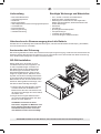
ISO-DIN-Installation
Dieses Gerät ist fur den Einbau in einen
2.0-DINArmaturenschacht vorgesehen, der
in vielen Importfahrzeugen vorhanden ist.
Das Gerät verfugt auf den Gehäuseseiten
über Bohrungen mit Gewinde, die für die
Original-Montageklammern mancher Fahr-
zeuge von Toyota, Nissan, Mitsubishi, Isuzu,
Hyundai und Honda zur Montage des Radios
im Armaturenbrett verwendet werden können.
Bitte wenden Sie sich an einen lokalen Fach-
betrieb für Stereogeräte für Fahrzeuge, wenn
Sie Hilfe bei dieser Montage benötigen.
1. Entfernen Sie das Original-Radio aus dem
Armaturenbrett bzw. der Mittelkonsole.
Bewahren Sie alle Teile und Klammern auf,
da diese fur die Montage des neuen Radios
erforderlich sind.
2. Bringen Sie die Original-Haltevorrichtun-
gen sowie das Montagezubehör des alten
Radios am neuen Radio an.
VORSICHT: Verwenden Sie keine
Schrauben, diegrößer als M5x6 mm sind.
Durch längere Schrauben werden unter
Umständen Komponenten im Inneren
des Gehäuses berührt und beschädigt.
ACHTUNG! Installieren Sie das Gerät so, dass die Fahrsicherheit nicht beeinträchtigt wird.

4
4
3. Halten Sie das Radio vor die Öffnung im Armaturenbrett, sodass die Verkabelung durch das Armaturenbrett
geführt werden kann. Beachten Sie das Schaltbild und stellen Sie sicher, dass alle Verbindungen mithilfe von
Kabelsicherungen oder Isolierband geschutzt und isoliert sind. Wenn die Verkabelung abgeschlossen ist,
verbinden Sie die ISO-Steckverbinder mit den entsprechenden Anschlussen auf der Ruckseite des Gehäuses.
Schalten Sie das Gerät ein, um die Funktion zu prufen (die Zundung des Fahrzeugs muss eingeschaltet sein).
Kann das Gerät nicht eingeschaltet werden, überprüfen Sie die Verkabelung, bis Sie den Fehler gefunden
haben.
4. Montieren Sie das neue Radio im Armaturenbrett oder in der Mittelkonsole, indem Sie die in Schritt 1
beschriebenen Arbeiten in umgekehrter Reihenfolge ausfuhren.
ACHTUNG! Achten Sie darauf, dass die Fahrzeugverkabelung nicht beschädigt wird.
HINWEIS: Der Endbenutzer ist dafür verantwortlich, die Montage und den Betrieb des Geräts entsprechend
den Gesetzen der Region und des Landes sicherzustellen. Das Kabel der HANDBREMSE muss wie in der
Bedienungsanleitung angegeben angeschlossen werden.
ACHTUNG: Die Lüftungsschlitze dürfen nicht verdeckt werden, da das Gerät ansonsten überhitzen und so
beschädigt werden kann.
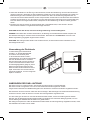
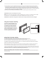
Verwendung der Zierblende
Im Lieferumfang ist eine Zierblende
enthalten, um die Montagefexibilität
zu erhöhen. Der Receiver passt
in das Armaturenbrett der meisten
Importfahrzeuge, ohne das Armaturenbrett
bzw. den Einbauschacht zu verändern.
Das Armaturenbrett mancher Fahrzeuge
fur den US-amerikanischen Markt ist fur
ein DIN-Doppelgehäuse geeignet, jedoch
bleibt nach dem Einbau zwischen dem
Radio unddem Armaturenbrett ein kleiner
Spalt. Verwenden Sie in diesem Fall die
passende Zierblende, um einen möglichen
Spalt zu verdecken.
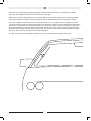
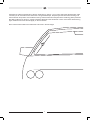
ANBRINGEN DER DAB+ ANTENNE
Die Antenne muss so montiert werden, dass sie die Sicht beim Fahren nicht beeinträchtigt.
Die Antenne sollte vorzugsweise von innen an der Windschutzscheibe angebracht werden.
Aufgrund der Polarisation des DAB Sendesignals muss die Antenne senkrecht zum Boden angebracht werden.
Der Abstand zu anderen Antennen sollte über 80 mm betragen. Bei Fahrzeugen mit Windschutzscheibenheizung
ist darauf zu achten, dass die Antenne nicht über den Heizungsdrähten angebracht wird.
Vor dem Anbringen der Antenne muss die Windschutzscheibe sauber, trocken und fettfrei gemacht werden.
Reinigen Sie die Windschutzscheibe gegebenenfalls und entfernen Sie restlos das Reinigungsmittel, um eine
sichere Haftung des Klebebandes der Antenne zu gewährleisten.
Bei niedrigen Temperaturen sollte die Windschutzscheibe mittels der Fahrzeugheizung aufgewärmt werden, damit
das Klebeband der Antenne sicher haftet.

5
Die Antenne ist zur einmaligen Montage (Aufkleben) bestimmt. Bitte die Antenne nicht entfernen und wieder
anbringen. Das Klebeband wird durch das Abnehmen beschädigt.
Bestimmen Sie gemäß der Hinweise oben den Einbauplatz für die Antenne. Entfernen Sie die weiße Schutzfolie
auf der Rückseite des schwarzen Antennengehäuses, die das Klebeband für das Antennengehäuse abdeckt.
Lösen Sie die gelbe Schutzfolie des dünnen Antennendrahtes ca. 2 cm auf jeder Seite vom Klebeband. Achten
Sie darauf, dass sie die dünnen Antennenleitungen nicht abbrechen. Fixieren Sie das schwarze Antennengehäuse
provisorisch mit Klebeband auf der Windschutzscheibe und drücken Sie auf das schwarze Gehäuse. Halten Sie
die Antennenleitungen und ziehen Sie die übrige gelbe Schutzfolie nach und nach ab und drücken Sie dabei die
Klebefolie fest an die Windschutzscheibe. Drücken Sie noch einmal auf das schwarze Antennengehäuse. Stellen
Sie sicher, dass fest es an der Windschutzscheibe befestigt ist.
Verlegen Sie nun das Antennenkabel zum DAB-Tuner und schrauben Sie den Antennenstecker fest.

6
6
What’s in the Box Tools and Supplies
• MAC 520 DAB Head Unit
• Double DIN Half Sleeve Install Bracket
• Custom Cosmetic Trim Ring
• Hardware Bag
• Power / Speaker Harness with ISO connectors
• A/V Input/Output Harness
• External Microphone
• Owner’s Manual
• Installation Guide
You will need these tools and supplies for installation:
• Torx type, fat-head and Philips screwdrivers
• Wire cutters and strippers
• Tools to remove existing radio (screw driver, socket
wrench set or other tools)
• Electrical tape
• Crimping tool
• Volt meter/test light
• Crimp connections
• 18 gauge wire for power connections
• 16 – 18 gauge speaker wire
Disconnecting the Battery
To prevent a short circuit, be sure to turn off the ignition and remove the negative (-) battery cable prior to
installation.
Replacing the Fuse
The fuse is located next to the receptacle for the Power / Speaker Harness. When replacing the fuse, use a new
15A replacement fuse. Using a fuse with an improper rating could damage the unit and cause a fre.
ISO-DIN Installation
This unit is designed to ft into a 2.0 DIN
dashboard opening, found in many impor-
ted cars. The unit has threaded holes in the
chassis side panels which may be used with
the original factory mounting brackets of some
Toyota, Nissan, Mitsubishi, Isuzu, Hyundai
and Honda vehicles to mount the radio to the
dashboard. Please consult with your local car
stereo specialty shop for assistance on this
type of installation.
1. Remove the existing factory radio from the
dashboard or center console mounting.
Save all hardware and brackets as they will
be used to mount the new radio.
2. Remove the factory mounting brackets and
hardware from the existing radio and attach
them to the new radio.
CAUTION! Do not exceed M5 X 6MM
screw size. Longer screws may damage
components inside the chassis.
WARNING! Never install this unit where operation and viewing could interfere with safe driving conditions.

7
7
3. Place the radio in front of the dashboard opening so the wiring can be brought through the mounting sleeve.
Follow the wiring diagram carefully and make certain all connections are secure and insulated with wire nuts or
electrical tape. After completing the wiring connections, plug the ISO connectors into the mating sockets on the
rear of the chassis. Turn the unit on to confrm operation (vehicle ignition switch must be “on”). If the unit does not
operate, re-check all wiring until the problem is corrected.
4. Mount the new radio assembly to the dashboard or center console using the reverse procedure in step 1.
CAUTION! Be careful not to damage the car wiring.
NOTE: It is the end-users responsibility to install and operate this unit in a manner in accordance with local, state
and federal laws. The PARKING BRAKE wire MUST BE CONNECTED as directed in the manual.
CAUTION! Do not block the cooling fan exit. If blocked, the unit may overheat and become damaged.
Using the Cosmetic Trim Ring
A cosmetic trim ring is packaged with the
head unit for installation fexibility. This unit
will ft into most import dashes with little or
no modifcation to the dash board/cavity.
Some US domestic vehicle dashes will
accept a Double-DIN chassis, but there is
usually a small gap between the radio and
dash piece after installation is complete. In
this case, use the appropriate trim ring to
conceal any gaps that may be present.
MOUNTING THE DAB+ AERIAL
The aerial must be mount in such a manner that it does not impair vision when driving.
The aerial should preferably be mounted on the windscreen from the inside.
Due to the polarisation of the DAB transmission signal, the aerial must be mounted vertical to the ground.
The distance to other aerials must be more than 80 mm. On vehicles with windscreen heater, take care that the
aerial is not mounted on top of the heating wires.
Before applying the aerial, the windscreen must be clean, dry and free of grease. If necessary, clean the wind-
screen and remove all cleaning agent in order to ensure for a safe adhesion of the aerial adhesive tape.
In event of low temperatures, the windscreen should be warmed-up using the vehicle heater to allow the aerial ad-
hesive tape to bond safely. The aerial is only intended for being installed once (sticking on). Please do not remove
the aerial and remount it. The adhesive tape will be damaged when removed.
Determine the installation location of the aerial according to the instructions above.
Remove the white protective lm on the back side of the black aerial housing that conceals the adhesive tape for
the aerial housing.

8
Peel back the yellow protective lm of the thin aerial wire by approx. 2 cm on each side of the adhesive tape. Take
care that you do not break the thin aerial lines. Using adhesive tape, temporarily x the black aerial housing onto
the windscreen and press it onto the black housing. Hold the aerial line and peel off the remaining yellow protection
lm little by little and in doing so, press the adhesive lm tight to the windscreen. Press on the black aerial housing
again. Make sure that it is secured tightly on the windscreen.
Now route the aerial cable to the DAB tuner and screw in the aerial tight.

9
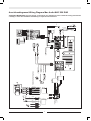
Anschlussdiagramm/ Wiring Diagram Mac Audio MAC 520 DAB
CAUTION! IMPORTANT! Incorrect wiring connections can damage the unit. Follow the wiring instructions
carefully, or have the installation handled by an experienced technician.
Black
SWC(Black)
Yellow
Green
PARKING/BRAKE (PINK)
REVERSE
Green/White
P.ANT/CNT (BLUE)
GPSAntenna
USB
input
Rear Right
Rear Left
Front Left
Front Right
White / Front L (+)
Grey with black stripe / Front R (-)
White with black stripe / Front L (-)
Grey / Front R (+)
Purple / Rear R (+)
Purple with black stripe / Rear R (-)
Green / Rear L (+)
Green with black stripe / Rear L (-)
YELLOW
RED
ORANGE
BLUE
GND
BATT+
ACC
Illumination
ANT.CONT
BLACK
Blue / ANT.CONT
Red/ACC
Black/GROUND
Yellow/BATTERY 12V+
Orange/Illumination
Orange / Illumination
Ye llow/Battery 12V(+)
Black/Ground
Red / ACC
Blue / ANT.CONT
POWER AMPLIFIER
AV-SYSTEM
Yellow
Red
Red
White
Red
Brown
White
White
SUB
OUT
AV-IN
REARFRONT
TMC module
Antenna
TM
C
CAMERA
VIDEOOUT
Brown
Microphone
Blue
Yellow
Yellow
White
DAB Antenna
LCD
Steering Wheel Control (SWC) requires
Dietz Interface Adapter (sold separately)


Lise-Meitner-Str. 9 • D-50259 Pulheim • Germany
www.mac-audio.de
InstallationGuide_V1 | Irrtum und technische Änderungen vorbehalten./Errors and technical modications reserved.
-
 1
1
-
 2
2
-
 3
3
-
 4
4
-
 5
5
-
 6
6
-
 7
7
-
 8
8
-
 9
9
-
 10
10
-
 11
11
-
 12
12


MAC Audio 520 DAB Installationsanleitung
- Kategorie
- Auto-Video-Systeme
- Typ
- Installationsanleitung
- Dieses Handbuch eignet sich auch für
in anderen Sprachen
- English: MAC Audio 520 DAB Installation guide
Verwandte Artikel
Andere Dokumente
-
JVC KD-NX5000 Bedienungsanleitung
-
Audiovox VME 9725 Installationsanleitung
-
JVC KD-LX3R Benutzerhandbuch
-
-
Audiovox VME 9425 Installationsanleitung
-
-
Blaupunkt Antenna Active DAB Installationsanleitung
-
-
-