Electrolux EIW60000X Benutzerhandbuch

Kategorie
Sanitärkeramik
Typ
Benutzerhandbuch
Instruction manual
REFRESHMENT CENTER
Built-in appliance
welcome to the world of Electrolux electrolux 3
Welcome to the world of Electrolux
Thank you for choosing a first class product from Electrolux, which hopefully
will provide you with lots of pleasure in the future.
The Electrolux ambition is to offer a wide variety of quality products that
make your life more comfortable.
You find some examples on the cover in this manual.
Please take a few minutes to study this manual so that you can take
advantage of the benefits of your new machine.
We promise that it will provide a superior User Experience delivering Ease-of-
Mind.
Good luck!
4 electrolux contents
Contents
Built-in appliance............................. 1
Electrical safety............................... 5
Appliance description ........................ 7
Identification plate........................... 8
Technical Characteristics.................... 8
Installation..................................... 9
Package content...................................9
1
Unit positioning................................ 10
2 Frontal spacer installation................... 11
3 Water mains and siphon connection....... 12
4 Install filter cartridge ........................ 13
5 CO2 bottle connection ....................... 13
6 Startup .......................................... 14
Using the Refreshment Center................... 15
Front touch panel.................................. 15
Dispensing ........................................... 15
Alarms ......................................... 16
Maintenance.................................. 19
Sanification + filtration cartridge............... 19
Environment care............................ 22
Electric diagram ............................. 23
Hydraulic diagram ........................... 24
Errata corrige ................................ 25
Guarantee/Customer Service .............. 33
The following symbols are utilized with this manual:
Safety information
Environment
Disposal directives
electrical safety electrolux 5
Electrical safety
This appliance conforms to the following safety electrical European
Directives:
This manual has been written for your own safety and of others.
Please read manual carefully before installation and/or use. Please
keep this instruction manual in a safe and dry place. This appliance
conforms to the following safety electrical European Directives:
2006/95/CE, 2004/108/CE, 98/37/CEE.
Please keep this instruction manual in a safe and dry place.
This manual has been written
for you own safety and of
others. Please read manual
carefully before installation
and/or use.
Electrical safety
The unit needs to be
connected to a power supply
line that conforms fully to
local safety regulations
regarding electrical safety. If
in doubt please have your
electrical system checked by
a specialized electrician.
Please do not try to repair
the unit as you might cause
additional damage. Contact
your nearest Technical
assistance center.
Remove power supply cord
before proceeding with repair
operations.
If the power supply cord
appears to be damaged,
please ask for a replacement
cord.
6 electrolux appliance description
Installation
Please handle appliance with
care to prevent damaging of
the refrigeration circuit.
Avoid prolonged exposure of
the appliance to direct
sunlight.
Please follow instruction
carefully before, during and
after installation.
If the appliance is
transported in vertical
position, please place in
horizontal (normal) position
and wait 1 hour for the oil to
return to the compressor
before turning unit on.
Do not bend water supply and
discharge tube excessively
during installation.
Use
Do not use the Refreshment
Center for something else
other than dispense cold,
carbonated, ambient water
and ice. An incorrect use of
the appliance may harm
people or cause damage to
the appliance itself.
Do not allow children to use
the appliance if not under
the supervision of adults.
Cleaning
Do not use metallic tools to
clean the appliance as it may
cause damage.
Environment
Please follow local disposal
regulations.
appliance description electrolux 7
Appliance description
The Refreshment Center is a
domestic appliance designed to
dispense purified cold, carbonated
and ambient temperature water and
ice-cubes.
The appliance has 2 nozzles from
which the following products can be
dispensed:
- Ambient temperature water
- Cold water
- Carbonated water
- Ice-Cubes.
Units
The unit is mainly composed of:
1 St. Steel front display
2 Filter head
3 Water dispense nozzle
4 Glass touch command panel
5 Ice dispense outlet
6 Drip tray
7 CO
2
bottle
8 H
2
O pressure regulator with
gauge
9 Filter cartridge
10 Power supply socket
11 Main on/off switch
12 H
2
O inlet
13 H
2
O drainage
2 31 4 5 6
7 8 9
13121110
8 electrolux identification plate
Identification plate
Should you need to contact a
technical Assistance Center,
make sure you have the serial
number handy for
identification. The serial
number is on the
identification plate in the side
of the appliance. Extract from
cabinet to identify plate.
MODEL PNC
xxx xxx xxxXXXXXXXX
xxxxxxxx
TYPE
SERIAL No.:
Refreshment Center
MADE IN ITALY
230 V ~ 50 Hz
MAX 190 W
Fig. 2
Technical Characteristics
Power Supply 230-240 V
Frequency 50 Hz
Power consumption 190 W
Cold water dispense capacity 2lt @ 1 l/min.
Carbonated water dispense capacity 2lt @ 1 l/min
Dispense temperature < 13°C
Water mains pressure (water inlet) > 2.0 bar
CO
2
pressure 2.5-4 bar
Filtration 0.5 micron
Filter capacity 2840 litres
Ambient temperature conditions range 18°C-32°C
Unit dimensions L x P x H (mm) 594x554xH378
Weight 38 Kg
Refrigerant gas R134a – 60gr
installation electrolux 9
Installation
Warning
In order for the unit to work
correctly, the Technical
Characteristics specification
chart on page 6 needs to be
observed.
Installation steps:
1. Refreshment Center assembly
inside kitchen
2. Frontal spacer installation
3. Water mains connection
4. Water filter connection
5. CO2 bottle connection
6. Electric power supply
Package content
Open package and immediately check
for any transport damages. During
installation please handle with care.
Inside you should find the following
material:
A. Refreshment Center
B. 2 Sliding Rails
C. Mounting base plate
D. 6 spacers 2x1mm, 2x2mm,
2x3mm
E. Eight 3,5x16mm and three M4x8
screws
Power supply cord
H
2
O inlet flexible hose and
discharge tube
2x
Filtration Cartridge
Sanitazing cartridge and liquid
A
B
C
D
E
8x
3x
10 electrolux installation
1 Unit positioning
Please install unit as far away
as possible from heat sources
Please install unit higher than
the water main in the kitchen
Please don’t install the
Refreshment Center farther
than 4m from the water main
or please use another water
inlet and discharge tubes.
Installing the machine into kitchen
furniture with proper characteristics
will ensure a correct operation of the
equipment.
Complying with the safety rules,
ensure a proper protection against
any contact with the electric
components and with the parts
protected only by functional
insulation, by housing the machine
correctly into the furniture.
All components that guarantee
protection, even a cover panel (for
instance, when the machine is
positioned at one of the ends of the
modular furniture), should be firmly
fixed so that they cannot be removed
without tools.
Install this machine at a certain
distance from refrigerators or
freezers, because the heat it emits
can impair their functioning.
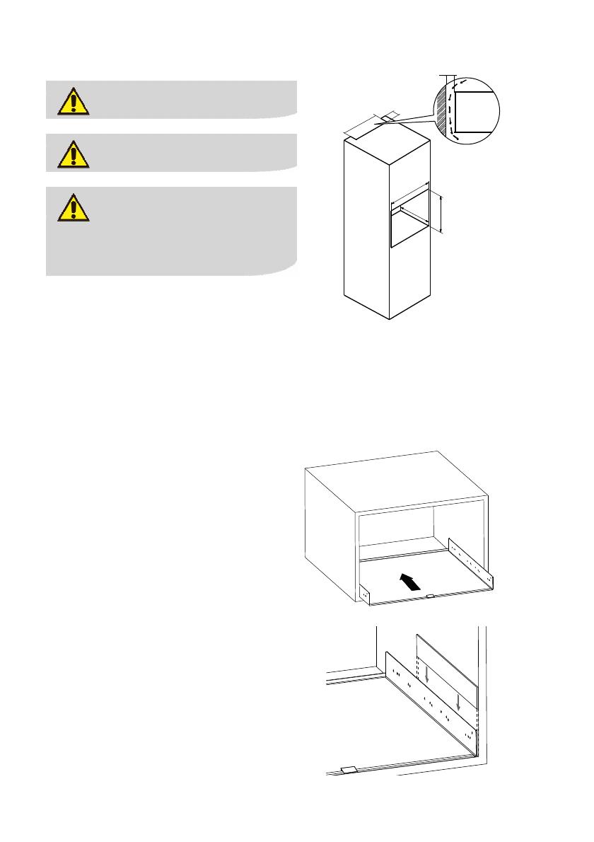
- The dimension requirements for
the kitchen cabinet are:
1.
Height(1):380mm
2.
Depth(2):560mm
3.
Width(3):560mm
5
4
0
5
0
1
2
3
50
- Install the mounting base plate
inside the kitchen cabinet after
checking after checking
dimension requirements as shown
in Fig. 3. If necessary, please use
the spacers to fix the mounting
base plate to the cabinet (Fig.
4).
Fig. 3
Fig. 4
installation electrolux 11
Please be sure that the
frontal edge of the mounting
base plate and the frontal
edge of the piece of
furniture are coincident
- Mount the 2 sliding rails onto the
base plate already placed in the
cabinet, using the eight
3,5x16mm self-threading screws
supplied.
- Place the Refreshment Center on
the sliding rails. Slide the
machine into the cabinet until
the “click” indicates that it is
locked into position.
2 Frontal spacer installation
When installing the Refreshment
Center near to other appliances, the
height of the other appliances (for
example an oven) could be 10mm
higher. To align the Refreshment
Center frontal panel to the others,
please fix the frontal spacer part to
the frontal panel using the nr.3 M4x8
screws as in figure below:
Fig. 5
Fig. 6
12 electrolux installation
3 Water mains and siphon connection
Warning
Connect only to potable
water mains.
All water mains connections
should be carried out by a
certified plummer.
Warning
Water mains pressure can be
set through the H
2
O pressure
regulator placed near the
CO
2
bottle. Please set it
after dispensing of at least
500cc of carbonated water.
Pressure should be lower
than 3.0 bars and higher than
2.0 bars.
Complete following operations (Fig.
8):
- Connect the flexible hose to the
H
2
O inlet (Fig.7) on the unit.
Connect water mains to flexible
hose.
- Connect discharge tube to
discharge barbed connection on
unit and to sink siphon (Fig.7).
Warning
Please do not install
Refreshment Center farther
than 4 meters or please get
longer inlet and discharge
tubes.
Water Inlet 3/4”
Water discharge 3/4”
Fig. 7
2x
installation electrolux 13
4 Install filter cartridge
Lift locking spring placed under drip
tray (Fig. 8).
Fig. 8
Pull unit from cabinet (Fig. 9). On the
left side of the unit please find the
filter cartridge (Fig. 1a).
Fig. 9
Remove filter plastic cap and install
filter in filter head as shown on filter
instruction booklet (Fig. 11).
Fig. 10
Check for water leaks.
5 CO2 bottle connection
Make sure the CO
2
bottle is tightly
fixed on the CO
2
pressure regulator.
Fig. 11
Open the pressure regulator valve and
set pressure to 3 bars on gauge (Fig.
12). Pressure can be increased to 4
bars to increase carbonation levels.
Fig. 12
14 electrolux installation
6 Startup
Warning
Before plugging unit to
power supply, please check
for correct power supply
voltage and frequency as
stated on Technical
Characteristics chart (see
page 8).
Fig. 13
Connect unit to 230V through
supplied cord (Fig. 13).
Electric supply circuit should conform
to local laws and regulations.
Warning
The supplier declines any
responsibility should any
safety rule not be respected
during installation.
Turn unit on through main on/off
switch on side of unit (Fig. 14). The
unit will undergo an initialization
process which will take approx. 4
minutes.
This preliminary operation will be
carried out every time the unit is
turned off and on through the main
on/off switch inside the cabinet.
During this process the touch control
panel is inactive.
After 4 minutes it’s possible to turn
unit on through on/off button on
touch control panel to activate all
functions.
At this point please wait approx.
2 hours before the unit reaches final
working temperatures in order to
dispense cold water, carbonated
water and ice-cubes. Ambient water
is ready immediately.
installation electrolux 15
Using the Refreshment Center
Front touch panel
1 Empty CO
2
bottle led
2 On/Off switch
3 Water ambient temperature
button
4 Carbonated water button
5 Cold water button
6 Ice dispense button
7 Light button On/Off
8 Exhaust filter led
Dispensing
After turning appliance on through
on/off switch on touch screen, wait
for cooling time before dispensing.
Place a glass under dispense nozzle.
Press button corresponding to desired
selection. Release until desired
dispense water level or number of ice-
cubes is reached. If you experience
CO
2
exhaust from nozzle, please wait
20 secons and restart dispensing
carbonated water.
1 2 3 4 5 6 7 8
16 electrolux alarms
Dispensing is signaled by the
corresponding led.
In order to dispense in bottles or
carafes, please extract dispense
nozzle by grabbing on sides of nozzle
and pulling forward.
Alarms
Led indications Message
Led blinks slowly
Filter is about to exhaust. 2800 liters have
been dispensed.
Please change filter as described in the
following chapters.
Led is lit
Filter is about to exhaust. 2900 liters have
been dispensed. Please change filter as
described in the following chapters.
Led is lit
All dispense buttons disabled.
3000 liters have been reached.
Please change filter as described in the
following chapters.
alarms electrolux 17
Carbonated
water led blinks
slowly
Carbonated water is disabled.
Protection on carbonation pump activated.
To reset status please turn unit off/on on
touch control panel after waiting for a while.
CO
2
bottle led on
Carbonated water is disabled.
CO
2
bottle is empty.
Replace CO
2
bottle to restore carbonated
water dispensing.
Please change CO
2
bottle as described in the
following chapters.
Leds
- ambient water
- ice
blink
simultaneously
Ice forming bin block alarm.
Restart unit through main on/off switch on side of unit
(Fig. 1b).
Leds
- ambient water
- cold water
- carbonated
water
blink
simultaneously
Volumetric turbine alarm. Two possible causes:
1. No water supply to unit
2. There’s water supplied to unit (dispensing
enabled) but volumetric turbine malfunction.
For the first case verify the presence of water supplied to
unit.
For the second case restart unit through on/off switch on
touch panel.
Leds
- carbonated
water
- ambient water
- cold water
- ice
blink
simultaneously
Main water tank fill alarm. Please check water supply to
unit. To reset status restart unit through main switch inside
cabinet (Fig 1b).
18 electrolux maintenance
All leds on
simultaneously
All dispense buttons disabled. 2 main causes:
1. Water present on base of unit. Possible leak.
2. Water level too high inside water tank. Water discharge
blocked.
For the first case switch off and dry the base of the unit.
For the second case restart unit through main switch inside
cabinet.
Should alarms repeat
themselves after all restart
attempts, please call service
assistance.
maintenance electrolux 19
Maintenance
Before any maintenance or
cleaning procedure, please
switch off the appliance and
disconnect it from main by
unplugging the power plug.
CO
2
bottle replacement
When the CO
2
led turns on, it’s
necessary to replace the CO
2
bottle
as described below:
1. Lift locking spring placed under drip
tray (Fig. 8).
2. Pull appliance from cabinet
(Fig. 15).
3. Grab the CO
2
bottle (Fig. 1a) and
extract it from it’s locking clip.
4. By holding the bottle fixed, turn
the pressure regulator clockwise to
remove from the bottle (Fig. 16).
Fig. 15
Fig. 16
5. Place new bottle under the
regulator and screw counter
clockwise till fully tightened (Fig.
17).
6. Lock bottle in place and pull the
unit into the cabinet.
Fig. 17
Sanification + filtration cartridge
When the exhaust filter led turns on, it is time to replace the filter cartridge:
20 electrolux maintenance
7. Lift locking spring placed under drip
tray (Fig. 8). Pull appliance from
cabinet
(Fig. 15).
8. Turn unit off through main on/off
switch (Fig. 1b).
9. Remove the filter cartridge form its
housing by rotating anti clock-wise
about a quarter turn (Fig. 18). This will
free the filter. Pull downward and
remove it paying attention to avoid water
leaks.
Fig. 18
10. Fill sanitizing cartridge with Neutral
Detergent. Insert the sanitizing
cartridge on the filter head by rotating
clock-wise a quarter turn (Fig. 19).
11. Dry any water from the base, that
could have leaked during this
operation.
12. Position under the water dispense
nozzle a container or large cup.
13. Turn on the appliance through the main
switch (Fig. 1b) while pressing the
“light” button for 3 seconds. This starts
the sanitizing mode. This will be shown
in the display as a moving red led
through all the buttons. During this
operation, the inside of the unit will be
sanitized. After this initial cleaning
cycle, the unit will dispense
automatically some cold and ambient
water mixed with sanitizing product.
Fig. 19
  • Page 1 1
  • Page 2 2
  • Page 3 3
  • Page 4 4
  • Page 5 5
  • Page 6 6
  • Page 7 7
  • Page 8 8
  • Page 9 9
  • Page 10 10
  • Page 11 11
  • Page 12 12
  • Page 13 13
  • Page 14 14
  • Page 15 15
  • Page 16 16
  • Page 17 17
  • Page 18 18
  • Page 19 19
  • Page 20 20
  • Page 21 21
  • Page 22 22
  • Page 23 23
  • Page 24 24
  • Page 25 25
  • Page 26 26
  • Page 27 27
  • Page 28 28
  • Page 29 29
  • Page 30 30
  • Page 31 31
  • Page 32 32
  • Page 33 33
  • Page 34 34
  • Page 35 35
  • Page 36 36
  • Page 37 37
  • Page 38 38
  • Page 39 39
  • Page 40 40

Electrolux EIW60000X Benutzerhandbuch

Kategorie
Sanitärkeramik
Typ
Benutzerhandbuch

in anderen Sprachen