Venjakob game standing cabinet w. feet Assembly Instructions
- Typ
- Assembly Instructions

Aufbauanleitung:
Standelemente mit Sockelfüße
Service Hotline: Tel. +49 5209/592-0
Internet: www.venjakob-moebel.de (Weitere Aufbauanleitungen)
Das mitgelieferte Befestigungsmaterial (Dübel und Schrauben) ist ausschließlich für die Befestigung von Bauteilen an Beton und/oder festem
Mauerwerk geeignet. Bitte beachten Sie auch bei den Wandmontageelementen die max. Belastungswerte. Die Wandbeschaffenheit ist idealerweise
bei Auftragserfassung zu erfragen und spätestens vor der Montage unbedingt von fachkundigem Personal zu prüfen. Bei abweichender
Beschaffenheit (z. B. Leichtbauwänden) ist eine andere, der Belastung angemessene Befestigung bauseits vorzunehmen. Klären Sie elektrische
Vorleistungen für Anschluss- und Gerätetechnik. Frei hängende Beleuchtungen erfordern Kabelkanallösungen auf oder unter Putz.
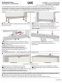
1. Transportschutz unterhalb des Sockelbodens abschrauben
und entsorgen. Stellfüße / Möbelgleiter mit dem Zapfen in den
Sockelboden setzen.
2. Ggf. Frontteile (Schubkästen, Klappen, Türen) ausbauen.
Möbelgleiter durch Drehen im Uhrzeigersinn auf den
Nullpunkt stellen, horizontal und vertikal ausrichten.
Korrekturen von innen mittels Inbusschlüssel SW4 oder von
außen mit Hand vornehmen. Löcher mit Abdeckkappen
ø10mm schließen.
3. Verbindung Korpusseiten (zwei Ausführungen möglich!): 4. Deckblattmontage (sofern nicht vormontiert):
Ausführung 1: Mit Tellerkopfschraube 4x30 mm, wenn nur
einseitig vorgebohrt ist.
Ausführung 2: Mit Möbelschraube M4x15mm und
Gewindeendhülse M4x25mm, wenn beide Seiten
durchgebohrt sind, bzw. vorgebohrte Löcher mit Ø 5mm
Bohrer durchbohren (gegen Ausrisse Holzstück o.Ä.
gegenlegen).
Deckblatt von innen mit Möbelschraube M4x25 mm
festschrauben.
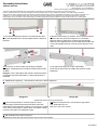
5. Zusatzartikel Beleuchtung: → siehe Aufbauanleitung "Anschluss Beleuchtung"
6.A Kippsicherung innen, Möbelhöhe ca. 89-140cm 6.B Kippsicherung außen, nur bei Möbelhöhe ca. 208cm
Mit kleinem Bohrer durch vormontierten Winkel und
Rückwand bohren (Bohrposition an Mauerwerk markieren). Ø
8mm Bohrung in Mauerwerk bohren. Dübel 8x51mm
verankern. Mit Spanplattenschraube 5x80 mm befestigen.
Set "Wandbestigung" verwenden. Anbringung oben auf dem
Deckblatt.
Fronten einsetzen, Zierkappen auf Türscharniere klipsen und Abdeckkappen auf Excentergehäuse setzen.
7. Griffe je nach Modell montieren (Griff mit Lasche für Holzfronten, Aufschraubgriff für Glastüren), Euroschraube 6x10,5mm
für Holzfronten bzw. Kunststoffschraube inkl. Kunststoffbuchse für Glastüren verwenden.
Variante 6.A oder Variante 6.B
(Lowboards ohne Kippsicherung)
13.10.2023

Assembly instructions:
Cabinet with feet
Service Hotline: Tel. +49 5209/592-0
Internet: www.venjakob-moebel.de (additional assembly instructions)
The fixture materials provided with this product (dowels and screws) are only suitable for fixing parts to concrete and/or solid
masonry. Please observe the maximum load that the wall-mounted elements can carry. Ideally, the suitability of the wall should be enquired
about when the order is made and must be checked by specialist staff before the cabinet is assembled at the latest. If the condition of the wall is not
suitable (e.g. if it is a lightweight partition wall), then another type of fixture suitable for the load that is to be carried should be used. Check the
electrical input of any connection or device technology. Free-hanging light fixtures require cable duct solutions that are either on or under plaster.
1. Unscrew the transport protection from beneath the base.
Place the adjustable feet / furniture gliders with the dowels in
the base.
2. Remove front parts (e.g. drawers, doors). Set the furniture
gliders to the zero point by turning them in a clockwise
direction and then adjust them vertically and horizontally.
Make any other adjustments from the inside with an Allen key
or from the outside by hand. Cover any holes with the cover
caps.
3. Connection of carcass sides (two designs possible!): 4. Top panel assempley (if not pre-assembled):
Design 1: If predrilled from one side use wafer head screws
4x30mm.
Design 2: Fix the side panels with furniture srews M4x15mm
and thread end sleeves M4x25mm, if both side panels are
predrilled.
Screw the top panel from the inside with furniture screws
M4x25mm.
5. Additional item lightning → See assembly instruction "Wiring diagramm"
6.A Inner anti-tip protection, furniture heigh 89-140cm 6.B Outer anti-tip protection, only furniture heigh 208cm
Drill through pre-assembled bracket and back panel with
small drill bit (mark the drilling position on the masonry). Drill Ø
8 mm holes in the masonry. Anchor 8x51 mm dowels. Fasten
into place with 5x80 mm chipboard screws.
Use “Wall fastening” set.
Affix to the top of the overlay.
Reattach the fronts and clip the decorative caps onto the door hinges!
Design 6.A or Design 6.B
(lowboards with no anti-tip protection)
7. Attach handles wih screws 6x10,5mm
13.10.2023
-
 1
1
-
 2
2


Venjakob game standing cabinet w. feet Assembly Instructions
- Typ
- Assembly Instructions
in anderen Sprachen
Verwandte Artikel
-
Venjakob X6 standing cabinet Assembly Instructions
-
-
-
-
-
-

