Venjakob game hanging lowboard Assembly Instructions
- Typ
- Assembly Instructions

Aufbauanleitung:
Hängelowboard Tiefe 53 cm
Service Hotline: Tel. +49 5209/592-0
Internet: www.venjakob-moebel.de (Weitere Aufbauanleitungen)
Das mitgelieferte Befestigungsmaterial (Dübel und Schrauben) ist ausschließlich für die Befestigung von Bauteilen an Beton und/oder festem
Mauerwerk geeignet. Bitte beachten Sie auch bei den Wandmontageelementen die max. Belastungswerte. Bei abweichender
Beschaffenheit (z. B. Leichtbauwänden) ist eine andere, der Belastung angemessene Befestigung bauseits vorzunehmen. Klären Sie elektrische
Vorleistungen für Anschluss- und Gerätetechnik. Frei hängende Beleuchtungen erfordern Kabelmanagement auf oder unter Putz.
Die genaue Position des Artikels an der Zimmerwand festlegen!
In Verbindung mit Vitrine (9770): Standardhöhe Oberkante Blatt => 545 mm
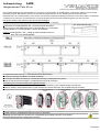
1. Bohrmaße für Aufhängeplatten Abb. 1 an Zimmerwand übertragen.
Ø8 mm Löcher in das Mauerwerk bohren und Dübel Ø8 x 51 mm einsetzen.
Aufhängeplatte mit 3 x Schraube Ø5,5 x 60 mm anschrauben.
Achtung: Aufhängeplatte = Set → Mittig an Sollbruchstelle knicken für
linke und rechte Aufhängeplatte!
Korpus an die Zimmerwand hängen, Aushängesicherung wieder schließen.
Ausrichtung mit der Wasserwaage über folgende Schritte:
5. Eine horizontale Korrektur ist mit der oberen Höhen-Stellschraube (1) am Hängebeschlag vorzunehmen.
6.
Mit der mittleren Tiefen-Stellschraube (2) den Abstand zur Zimmerwand bzw. die vertikale Neigung einstellen.
7.
Frontteile wieder einbauen und ggf. ausrichten.
8. Griffe montieren, Möbelgriffschraube M4 x 25 mm verwenden
Achtung: Alle Beschläge aus Gründen der Tragfähigkeit gleichmäßig ausrichten und belasten!
Maximale Belastbarkeit der Hängetypen beachten!
2. Zusatzartikel Beleuchtung: => Siehe Anschlussplan Beleuchtung
3. Sofern für Montage erforderlich: Frontteile ausbauen.
4. Im Korpus die untere Schraube (3 / Aushängesicherung) am Hängebeschlag öffnen,
Abb. 1
9700 L/R
Bohrmaße von Blatt-Außenkante für Aufhängeschienen
1 - Höhenverstellung
13 mm
2 - Tiefenverstellung
12 mm
3 - Aushängesicherung
Öffnen / Schließen
GAME
9701 L/R
9702 L/R
LL
LLLR
R
R
RR
Abb.: Beispiel Modell 9700L
12.10.2023

Assembly Instructions:
Hanging Cabinet depth 53 cm
Service Hotline: Tel. +49 5209/592-0
Internet: www.venjakob-moebel.de (additional assembly instructions)
The fixture materials provided with this product (dowels and screws) are only suitable for fixing parts to concrete and/or solid
masonry. Please observe the maximum load that the wall
‐
mounted elements can carry. If the condition of the wall is not suitable (e.g. if
it is a lightweight partition wall), then another type of fixture suitable for the load that is to be carried should be used. Check the electrical
input of any connection or device technology. Free
‐
hanging light fixtures require cable duct solutions that are either on or under plaster.
Mark out the exact position for the cabinet on the wall!
Together with cabinet 9770: standard height of the upper edge of the carcass =>545mm
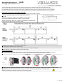
1. Transfer the drilling dimensions for the suspension rails Fig. 1
to the wall.
Drill Ø 8 mm holes in the masonry and insert Ø 8 x 40 mm dowels.
Screw in the suspension plates with 3 x Ø 5.5 x 60 mm screws.
hang the carcass on the wall and close the safety catch again.
Align with the spirit level:
5. The horizontal position of the cabinet can be corrected with the upper height adjustment screw (1) on suspension support.
6.
The middle depth adjustment screw (2) can be used to set the distance to the wall and the vertical inclination.
7.
Reattach the front parts and align if necessary.
8. Griffe montieren, Möbelgriffschraube M4 x 25 mm verwenden Attach the handles with the M4 x 23 mm furniture handle screws.
Pay attention: Align and load all supports evenly to ensure that the load-bearing capacity can be guaranteed!
Observe the maximum load-bearing capacity of the hanging cabinet!
2. Additional item lighting: => See lighting wiring diagram
3. If necessary for assembly: remove front parts.
4. In the carcass, open the lower screw (3 / safety catch) on the suspension support,
Attention: Suspension plate = set → Bend in the middle at the predetermined
breaking point for left and right suspension plates!
Fig. 1
Model
9700 L/R
Drilling dimensions of carcass outer edges for suspension rails
1 - High adjustment
13 mm
2 - Depth adjustment
12 mm
3 - Safety catch
Open / Close
GAME
Model
9701 L/R &
9702 L/R
LL
LLLR
R
R
RR
Fig.: Example model 9700L
Slot for
screwdriver PZ 2
12.10.2023
-
 1
1
-
 2
2


Venjakob game hanging lowboard Assembly Instructions
- Typ
- Assembly Instructions
in anderen Sprachen
- English: Venjakob game hanging lowboard
Verwandte Artikel
-
Venjakob X6 hanging lowboard Assembly Instructions
-
-
-
-
-
-