Pepperl+Fuchs UB6000-F42-I-V1-Y220443 Bedienungsanleitung
- Typ
- Bedienungsanleitung

Ultraschall-Sensor
Ultrasonic Sensor
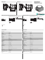
Abmessungen
Elektrischer Anschluss/Kurven/
Zusätzliche Informationen
Electrical Connection / Curves / Additional Information
Dimensions
Technische Daten
Technical data
UB6000-F42-I-V1-Y220443
Folientastatur
LED-Fenster
7,5
52,5
15,5
5,2
15,5
16
56
72
10
5
34
15
M12x1
80
65
80
65
16
34
A1A2
TEACH IN
MODE SET
-
Membrane keys
LED window
7.5
52.5
15.5
5.2
15.5
16
56
72
10
5
34
15
M12x1
80
65
80
65
16
34
A1A2
TEACH IN
MODE SET
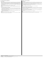
3 (BU)
1 (BN)
2 (WH)
4 (BK)
U
+ UB
Sync.
Analogausgang
- UB
Adernfarben gemäß EN 60947-5-2.
Normsymbol/Anschluss:
Steckverbinder V1
2
31
4
3
2
1
0
-1
-2
-3 0 1 2 3 4 5 6 7 8 9
X
Y
Abstand X [m]
Charakteristische Ansprechkurve
Abstand Y [m]
ebene Platte 100 mm x 100 mm
Rundstab, Ø 25 mm
A1A1 A2
Programmierung der Auswertegrenzen
Objektabstand
Steigende Rampe
Blindzone
A1A1 A2
Analogue output programmation
Object distance
Rising ramp
Unusable area
3
2
1
0
-1
-2
-3 0 1 2 3 4 5 6 7 8 9
X
Y
Characteristic response curve
Distance X [m]
Distance Y [m]
Flat surface 100 mm x 100 mm
Round bar, Ø 25 mm
3 (BU)
1 (BN)
2 (WH)
4 (BK)
U
+ UB
Sync.
Analogue output
- UB
Core colours in accordance with EN 60947-5-2.
Standard symbol/Connections:
Connector V1
2
31
4
Part. No.:
Date:
220443
12/11/2009 DIN A3 -> DIN
45-3053
Doc. No.:
Allgemeine Daten
Messbereich 400 ... 6000 mm
Erfassungsbereich 350 ... 6000 mm
Blindzone 0 ... 350 mm
Normmessplatte 100 mm x 100 mm
Wandlerfrequenz ca. 65 kHz
Ansprechverzug ca. 650 ms
Anzeigen/Bedienelemente
LED grün Power on
LED gelb Objekt im Auswertebereich
LED rot Störung
Elektrische Daten
Betriebsspannung UB10 ... 30 V DC , Welligkeit 10 %SS
Leerlaufstrom I0 60 mA
Eingang/Ausgang
Synchronisation bidirektional
0-Pegel: -UB...+1 V
1-Pegel: +4 V...+UB
Eingangsimpedanz: > 12 K
Synchronisationsimpuls: 100 s, Synchronisationsimpulspause: 2 ms
Synchronisationsfrequenz
Gleichtaktbetrieb 7 Hz
Multiplexbetrieb 7/n Hz, n = Anzahl der Sensoren
Ausgang
Ausgangstyp 1 Analogausgang 4 ... 20 mA
Auflösung 0,7 mm
Kennlinienabweichung ± 1 % des Endwertes
Reproduzierbarkeit ± 0,1 % des Endwertes
Lastimpedanz 0 ... 300
Temperatureinfluss ± 1 % des Endwertes
Umgebungsbedingungen
Umgebungstemperatur -25 ... 70 °C (248 ... 343 K)
Lagertemperatur -40 ... 85 °C (233 ... 358 K)
Mechanische Daten
Schutzart IP67
Anschluss Gerätestecker M12 x 1, 4-polig
Material
Gehäuse ABS
Wandler Epoxidharz/Glashohlkugelgemisch; Schaum Polyurethan, Deckel PBT
Masse 330 g
Werkseinstellungen
Ausgang Auswertegrenze A1: 400 mm
Auswertegrenze A2: 6000 mm
steigende Rampe
Schallkeule breite Ultraschallkeule
Normen- und Richtlinienkonformität
Normenkonformität
Normen EN 60947-5-2:2007
IEC 60947-5-2:2007
General specifications
Measuring range 400 ... 6000 mm
Sensing range 350 ... 6000 mm
Unusable area 0 ... 350 mm
Standard target plate 100 mm x 100 mm
Transducer frequency approx. 65 kHz
Response delay approx. 650 ms
Indicators/operating means
LED green Power on
LED yellow object in evaluation range
LED red error
Electrical specifications
Operating voltage UB10 ... 30 V DC , ripple 10 %SS
No-load supply current I0 60 mA
Input/output
Synchronization bi-directional
0 level -UB...+1 V
1 level: +4 V...+UB
input impedance: > 12 KOhm
synchronization pulse: 100 s, synchronization interpulse period: 2 ms
Synchronization frequency
Common mode operation 7 Hz
Multiplex operation 7/n Hz, n = number of sensors
Output
Output type 1 analogue output 4 ... 20 mA
Resolution 0.7 mm
Deviation of the characteristic curve ± 1 % of full-scale value
Repeat accuracy ± 0.1 % of full-scale value
Load impedance 0 ... 300 Ohm
Temperature influence ± 1 % of full-scale value
Ambient conditions
Ambient temperature -25 ... 70 °C (248 ... 343 K)
Storage temperature -40 ... 85 °C (233 ... 358 K)
Mechanical specifications
Protection degree IP67
Connection connector M12 x 1, 4-pin
Material
Housing ABS
Tr a n sd ucer epoxy resin/hollow glass sphere mixture; foam polyurethane, cover PBT
Mass 330 g
Factory settings
Output evaluation limit A1: 400 mm
evaluation limit A2: 6000 mm
rising slope
Beam width wide beam width
Compliance with standards and directives
Standard conformity
Standards EN 60947-5-2:2007
IEC 60947-5-2:2007

Adressen / Addresses / Adresses / Direcciónes / Indirizzi
Contact Pepperl+Fuchs GmbH · 68301 Mannheim · Germany · Tel. +49 621 776-4411 · Fax +49 621 776-27-4411 · E-mail: [email protected]-fuchs.com
Worldwide Headquarters: Pepperl+Fuchs GmbH · Mannheim · Germany · E-mail: info@de.pepperl-fuchs.com
USA Headquarters: Pepperl+Fuchs Inc. · Twinsburg · USA · E-mail: fa-info@us.pepperl-fuchs.com
Asia Pacific Headquarters: Pepperl+Fuchs Pte Ltd · Singapore · E-mail: [email protected]perl-fuchs.com · Company Registration No. 199003130E
For more contact-adresses refer to the catalogue or internet: http://www.pepperl-fuchs.com
Description of Sensor Functions
Synchronization
This sensor features a synchronization input for suppressing ultrasonic mutual interference ("cross talk"). If this input is not connected,
the sensor will operate using internally generated clock pulses. It can be synchronized by applying an external square wave. The pulse
duration must be 100 μs. Each falling edge of the synchronization pulse triggers transmission of a single ultrasonic pulse. If the syn-
chronization signal remains low for 1 second, the sensor will revert to normal operating mode. Normal operating mode can also be
activated by opening the signal connection to the synchronization input.(See note below)
If the synchronization input goes to a high level for > 1 second, the sensor will switch to standby mode, indicated by the green LED. In
this mode, the outputs will remain in the last valid output state.
Note:
If the option for synchronization is not used, the synchronization input has to be connected to ground (0 V).
The following synchronization modes are possible:
1. Several sensors (max. number see technical data) can be synchronized together by interconnecting their respective synchronization
inputs. In this case, each sensor alternately transmits ultrasonic pulses in a self multiplexing mode. No two sensors will transmit puls-
es at the same time. (See note below)
2. Multiple sensors can be controlled by the same external synchronization signal. In this mode the sensors are triggered in parallel and
are synchronized by a common external synchronization pulse.
3. A separate synchronization pulse can be sent to each individual sensor. In this mode the sensors operate in external multiplex mode.
(See note below)
4. A high level (+UB) on the synchronization input switches the sensor to standby mode.
Note:
Sensor response times will increase proportionally to the number of sensors that are in the synchronization string. This is a result of the
multiplexing of the ultrasonic transmit and receive signal and the resulting increase in the measurement cycle time.
Beschreibung der Sensorfunktionen
Synchronisation
Der Sensor ist mit einem Synchronisationseingang zur Unterdrückung gegenseitiger Beeinflussung durch fremde Ultraschallsignale aus-
gestattet. wenn dieser Eingang unbeschaltet ist, arbeitet der Sensor mit intern generierten Taktimpulsen. Er kann durch anlegen externer
Recheckimpulse synchronisiert werden. Die Pulsdauer muss 100 μs betragen. Jede fallende Impulsflanke triggert das Senden eines
einzelnen Ultraschallimpulses. Wenn das Signal am Synchronisationseingang 1 Sekunde Low-Pegel führt, geht der Sensor in die nor-
male, unsynchronisierte Betriebsart zurück. Dies ist auch der Fall, wenn der Synchronisationseingang von externen Signalen abgetrennt
wird.(siehe Hinweis unten)
Liegt am Synchronisationseingang ein High-Pegel > 1Sekunde an, geht der Sensor in den Standby. Dies wird durch die grüne LED an-
gezeigt. In dieser Betriebsart bleiben die zuletzt eingenommenen Ausgangszustände erhalten.
Hinweis:
Wird die Möglichkeit der Synchronisation nicht genutzt, muss der Synchronisationseingang mit Massepotential (0V) verbunden werden.
Folgende Synchronisationsarten sind möglich:
1. Mehrere Sensoren (max.Anzahl siehe Technische Daten) können durch einfaches Verbinden ihrer Synchronisationseingänge syn-
chronisiert werden. In diesem Fall arbeiten die Sensoren selbstsynchronisiert nacheinander im Multiplex-Betrieb. Zu jeder Zeit sen-
det immer nur ein Sensor. (siehe Hinweis unten)
2. Mehrere Sensoren können gemeinsam von einem externen Signal angesteuert werden. In diesem Fall werden die Sensoren parallel
getriggert und arbeiten zeitsynchron, d. h. gleichzeitig.
3. mehrere Sensoren werden zeitversetzt durch ein externes Signal angesteuert. In diesem Fall arbeitet jederzeit immer nur ein Sensor
extern synchronisiert. (siehe Hinweis unten)
4. Ein High-Pegel (+UB) am Synchronisationseingang versetzt den Sensor in den Standby.
Hinweis:
Die Ansprechzeit der Sensoren erhöht sich proportional zur Anzahl an Sensoren in der Synchronisationskette. Durch das Multiplexen
laufen die Messzyklen der einzelnen Sensoren zeitlich nacheinander ab.
-
 1
1
-
 2
2


Pepperl+Fuchs UB6000-F42-I-V1-Y220443 Bedienungsanleitung
- Typ
- Bedienungsanleitung
in anderen Sprachen
Verwandte Artikel
-
Pepperl+Fuchs UB6000-F42-I-V15 Bedienungsanleitung
-
-
-
-
-
-
-