
Gebrauchsanweisung
Operators Guide
Version 2.0
Art.Nr. 2632807

2
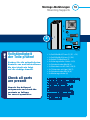
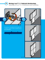
Herzlichen Glückwunsch
zum Kauf Ihrer twall
®
PLUS.
Bitte lesen Sie sich die Gebrauchsanweisung vor
Aufbaubeginn aufmerksam durch.
Prüfen Sie die Vollständigkeit der Baugruppen
anhand des beigefügten Lieferscheins.
Es sollten folgende Packeineiten nun bereitstehen:
- Paket Trägergestell
- Paket Abstützungen
- Paket(e) mit Modul(en)
- Paket mit PC und Haltearm für PC
Alles komplett – dann kann es sofort losgehen.
Bitte folgen Sie unbedingt der nachstehenden
Reihenfolge bei der Montage der Einzelteile.
Congratulations
on the purchase of your twall
®
PLUS.
Please read the operating instructions carefully
before starting assembly.
Check that all the assemblies are complete using
the attached delivery note.
The following packaging units should be provided:
- Package support frame
- Package supports
- Package(s) with training module(s)
- Package with PC and holding arm for PC
Everything present - then you can get going straight
away. Please ensure that you follow the sequence
below when tting the individual parts.
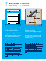
Gefahrenhinweise:
1. Allgemeine Gefahrenhinweise:
Der Betrieb der twall
®
PLUS darf nur in
vollständigem Aufbauzustand erfolgen.
Zur Vermeidung von Verletzungen ist unbe-
dingt die Aufbaureihenfolge einzuhalten! In der
Gebrauchsanleitung nden Sie eine detaillierte
Beschreibung.
Zur Vermeidung von Verletzungen, (z. B.
Schnitt- oder Risswunden durch mechanisch
bearbeitete Oberächen) müssen die Abdeck-
kappen unbedingt montiert werden.
Prüfen Sie täglich die Standsicherheit Ihrer
twall
®
PLUS, indem Sie auf den festen Sitz der
Montageelemente achten.
Hazard warnings:
1. General hazard warnings:
The twall
®
PLUS must only be operated when
fully assembled.
To avoid injury, the assembly sequence must
be adhered to without fail. You will nd a de-
tailed description in the operating instructions.
To avoid injury, (e.g. cuts or lacerations from
mechanically processed surfaces), it is vital that
the protective caps are tted.
Check the stability of your twall
®
PLUS, each
day by paying attention to the seating of the
mounting elements.

3
Zur Vermeidung von elektrischen Schlägen ist
die Unversehrtheit der Netzanschlussleitung vor
jedem Einsatz zu überprüfen.
Der Betrieb der twall
®
PLUS mobil ist nur mit
originalen Gegengewichten und Abstützungen
zulässig.
Die twall
®
PLUS ist kein Klettergerät! Das
Heranhängen oder Klettern am Gestell ist
verboten!
Der Aufenthalt hinter der twall
®
PLUS mobil
ist nur zu Montagezwecken gestattet.
Der Aktionsbereich vor der twall
®
PLUS
muss frei von Hindernissen und Unebenheiten
sein, um eine Sturzgefahr zu reduzieren.
Die twall
®
PLUS ist ein Indoor-Gerät und darf
nur nach Ergreifen geeigneter Maßnahmen
im Freien verwendet werden (z.B. durch die
Verwendung von Zelten, zusätzlichen Ge-
gengewichten oder Verankerungen). In allen
Fällen trägt hinsichtlich der Standsicherheit der
Betreiber die Verantwortung!
Zur Montage der twall
®
PLUS ist nur Werk-
zeug aus dem Lieferumfang zu verwenden. Das
notwendige Vorspannmoment wird nur erzeugt,
wenn das Werkzeug am langen Schenkel
bedient wird.
Bei der Vormontage der Prolverbinder
ist auf eine exakte Montage zu achten, um
die notwendige Festigkeit und Sicherheit zu
gewährleisten.
To avoid electric shocks, the integrity of the
power supply cable must be checked before
each use.
Operation of the twall
®
PLUS mobile is only
permitted with original counter weights and
supports.
The twall
®
PLUS is not a climbing frame! Han-
ging from or climbing on the frame is forbidden.
Staying behind the twall
®
PLUS mobile is only
allowed for installation purposes.
The eld of action before the twall
®
PLUS
must be free from obstacles and unevenness to
reduce the risk of falling.
The twall
®
PLUS is an indoor training device
and must only be used outdoors after taking
appropriate measures (e.g. using tents, additio-
nal counter weight or anchorage points). In all
cases, with respect to stability, the responsibility
lies with the operator.
To install the twall
®
PLUS only tools from the
delivery package are to be used. The necessary
pre-tensioning torque is only generated if the
tool on the long arm is used.
When pre-installing the prole connectors,
take care to ensure an exact t, in order to
guarantee the necessary solidity and security.

4
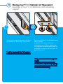
Das mitgelieferte Zubehör kann
in Abhängigkeit des technischen
Fortschrittes geändert werden.
The accessories supplied can be
changed dependent upon techni-
cal progress.
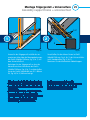
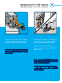
2. Gefahrenhinweise bei der
Montage der Module / Inbetrieb-
nahme des Gesamtgerätes
Die Montage der Module muss durch zwei
Personen erfolgen.
Es besteht beim Einlegen der Gegengewichte
eine erhöhte Quetschgefahr. Achten Sie daher
beim Einlegen der Gewichte auf Ihre Hände.
Bei Arbeiten hinter der twall
®
PLUS mobil
besteht eine erhöhte Sturzgefahr.
Die vorgeschriebene Kabelführung ist unbe-
dingt zuhalten.
Vor der Benutzungsfreigabe ist die
funktions- und sicherheitsgerechte Montage zu
überprüfen.
2. Hazard warnings during ins-
tallation of the modules / start
up of the whole apparatus.
Installation of the modules must be carried
out by two people.
There is an increased risk of being crushed
when inserting the counter weights. Please
watch your hands when inserting weights.
When working behind the twall
®
PLUS
mobile there is an increased risk of falling.
The previously described cable routing
must be strictly observed.
Before release for use a check must be
made for functional and correct safety-related
installation.

5
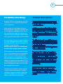
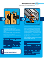
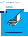
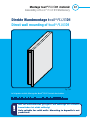
Produktbeschreibung:
Die twall
®
PLUS ist ein interaktives Gerät, das
Lichtimpulse nutzt, um gezielt Bewegungsab-
läufe zu generieren.
Dabei werden mit Leuchtfeldern, die durch
Berührung wieder ausgeschaltet werden, räum-
liche Bewegungen vorgegeben. Somit kann je
nach ausgeführtem Programm Kondition, Be-
weglichkeit, Reaktionsfähigkeit und bei Bedarf
auch spezische Kraftausdauer trainiert werden.
Die verschiedenen Elemente reagieren wahlwei-
se in einer vorprogrammierten oder in zufälliger
Reihenfolge, Position und Geschwindigkeit. Die
Aufgabe ist immer dieselbe:
durch kurzes Berühren (T=TOUCH) müs-
sen die Lichter ausgeschaltet werden.
Softwaregesteuerte Programmabläufe ermög-
lichen, je nach Modulversion, eine individuelle,
ebenso wie eine in Gruppen durchgeführte
Verbesserung der Leistungsfähigkeit. Durch
die einzelne Ansteuerung jedes Elements ist es
möglich, den aktiven Bereich der twall
®
PLUS
auf Körpergröße, Reaktionsradius und visuellen
Wahrnehmungsbereich sowie taktile Situation
der Anwenders abzustimmen.
Darüber hinaus erlaubt die farbliche Stimulie-
rung die Einbeziehung kognitiver Aufgaben-
stellungen. Außerdem ermöglicht die geringe
Bautiefe des Moduls einen unkomplizierten
Einbau in vorhandene Raumkonzepte.
Product description:
The twall
®
PLUS is an interactive device which
uses light impulses to generate motion sequen-
ces in a specic way.
Spatial movements are simulated using illumi-
nated panels which are switched off by touch.
According to the training programme therefore,
condition, exibility, the ability to react and, if
required, specic muscular endurance can all be
trained.
The different elements can react either in a pre-
programmed or random sequence and position
and at a pre-programmed or random speed. The
task is always the same:
by briey touching (T= TOUCH) you have
to turn off the lights.
Depending on the module version, software-
controlled programme ows enable individual
training and group training. By means of the
individual control of each element, it is possible
to adjust the training area of the twall
®
PLUS
to body size, reaction radius and visual percep-
tion area, as well as to the tactile situation of
those training.
In addition the colour stimulation allows the
inclusion of cognitive tasks. Moreover, the
small size of the training module means that it
can easily be incorporated into existing room
designs.

6
Bestimmungsgemäßer
Gebrauch
Die twall
®
PLUS dient ausschließlich der Erzeu-
gung des Bewegungsanreizes bei Menschen
und der Erzeugung von Lichteffekten.
Die Überprüfung der Eignung der Programme
für die Nutzer obliegt dem Betreiber.
Zum Betrieb der twall
®
PLUS ist ausschließlich
das mitgelieferte Netzteil zu nutzen.
Ein Dauerbetrieb aller Leuchtfelder mit maxima-
ler Helligkeit ist nicht zulässig, da dies zu einer
starken Erwärmung der LED-Module führe kann.
Spielprogramme, die eine Leuchtdauer
einzelner oder aller Leuchtfelder länger als zwei
Minuten erzwingen, sind unzulässig und führen
zu Garantieverlust.
Normal use
The twall
®
PLUS is used solely to generate
movement stimulation in people and to produce
lighting effects.
It is the responsibility of the operator to check
the suitability of the training programme for the
users.
Only the mains adaptor supplied with the
twall
®
PLUS should be used to operate it.
Continuous operation of all pushbutton panels
at maximum brightness is not permissible,
as this can lead to overheating of the LED
modules.
Games programmes which force a period of
illumination of individual or all the pushbutton
panels for longer than two minutes are not
permissible and invalidate the guarantee.

7
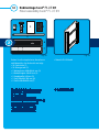
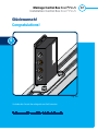
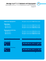
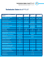
Inhaltsverzeichnis
Table of contents
Mobile twall
®
PLUS Versionen
Mobile twall
®
PLUS Versions
Gebrauchsanweisung Software nden Sie im Media-Bereich
unter www.twall.de.
Operating instructions Software can be found in the media
area at www.twall.de.
Inhaltsverzeichnis
Table of contents
7 Inhaltsverzeichnis
8 Montage Universalfuß
23 Montage Trägergestell
31 Endmontage twall
®
PLUS D1
40 Endmontage twall
®
PLUS D2
48 Endmontage twall
®
PLUS D4
58 Montage Abstützungen
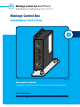
64 Montage Control Box
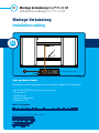
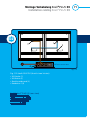
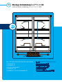
70 Montage Verkabelung
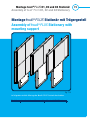
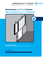
73 Montage twall
®
PLUS Stationär
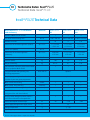
91 Technische Daten twall
®
PLUS
93 Zubehör twall
®
PLUS
7 Table of contents
8 Assembly of universal foot
23 Assembly of support frame
31 Final assembly twall
®
PLUS D1
40 Final assembly twall
®
PLUS D2
48 Final Assembly twall
®
PLUS D4
58 Mounting Supports
64 Installation Control Box
70 Mounting cabling
73 Montage twall
®
PLUS stationary
92 twall
®
PLUS Technical Data
95 twall
®
PLUS Accessories

8
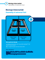
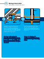
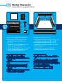
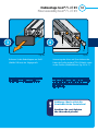
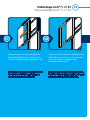
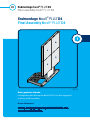
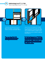
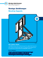
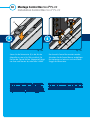
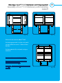
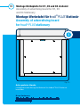
Sehr geehrter Kunde,
nachfolgend wird der Aufbau des Universalfußes der twall
®
PLUS
Schritt für Schritt erläutert.
Fig. 1. zeigt den komplett montierten Universalfuß.
Dear Customer
Below is a step by step guide to the assembly of the universal foot of the
twall®PLUS
Fig. 1 shows the completely assembled universal foot.
Montage Universalfuß
Assembly of universal foot
Ansicht
unten
View from
below
View from
above
Ansicht
oben
1
Fig. 1
Montage Universalfuß
Assembly of universal foot

9
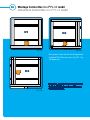
Montage Universalfuß
Assembly of universal foot
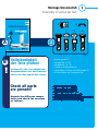
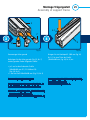
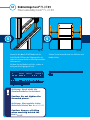
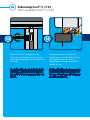
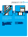
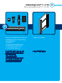
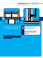
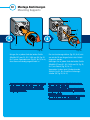
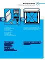
Vollständigkeit
der Teile prüfen!
• 6 Anker gerade (1)
• 4 Biegeanker 23° (2)
• 8 Biegeanker -23° (3)
• 2 Anker mit Vierkantkopf (4)
• 2 Blattfedern für Anker mit Vierkantkopf (5)
• 20 Querstücken mit Gewindestift (6)
56
2
Packen Sie die verschiedenen
Komponenten aus und kontrol-
lieren Sie den Inhalt wie folgt:
B
Fig. 2
3
4
1
2
Gebrauchsanweisung
Operators Guide
A
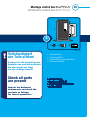
Check all parts
arepresent!
Unpack the different compo-
nents and check the contents
as follows:
• 6 Anchor pieces, straight (1)
• 4 Bent anchor pieces 23° (2)
• 8 Bent anchor pieces -23° (3)
• 2 Square headed anchor pieces (4)
• 2 Leaf springs for square headed anchor piece (5)
• 20 crosspieces with threaded pin (6)

10
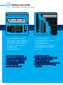
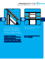
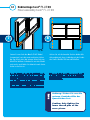
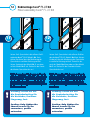
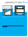
• 9 Gummi-Abdeckprole (schwarz) (1)
• 2 Abdeckkappen (schwarz) 40x80mm (2)
• 2 Abdeckkappen (schwarz) 80x80mm (3)
• 18 Linsenanschschrauben M8x14 (4)
• 18 T-Nutensteine M8 mit Kugel (5)
• 6 Auagewinkel (6)
• 4 Kombiprole 440mm (7)
3
4
5
6
7
1
2
Fig. 3 Fig. 4
5
1
2
3
4
5
3 41
2
Montage Universalfuß
Assembly of universal foot
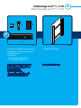
• 1 Prol 80x80x1760mm (1)
• 2 Prole 40x80x1182mm mit Winkel,
links 23°, rechts 23° (2)
• 1 Prol 40x80x1072mm (3)
• 1 Prol 40x80x850mm mit Langloch (4)
• 2 Prole 40x80x586mm mit Winkel,
links 23° (5)
• 9 rubber cover proles (black) (1)
• 2 protective caps (black) 40x80mm (2)
• 2 protective caps (black) 80x80mm (3)
• 18 button head screws M8x14 (4)
• 18 T-nuts M8 with ball bearing (5)
• 6 Support brackets (6)
• 4 Combi proles 440mm (7)
• 1 Prole 80x80x1760mm (1)
• 2 Proles 40x80x1182mm with 23 ° angle,
to the left, and 23° to the right (2)
• 1 Prole 40x80x1072mm (3)
• 1 Prole 40x80x850mm with elongated hole (4)
• 2 Proles 40x80x586mm with 23° angle,
to the left (5)

11
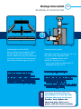
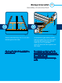
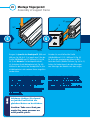
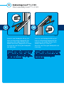
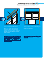
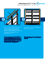
Anordnung der einzelnen Prole.
Achten Sie darauf, dass die glatten Flächen
der Prole 2, 3 und 5 nach oben zeigen.
Prol 1 und 4 besitzt Löcher, die für den wei-
teren Aufbau nötig sind. Hier sollten jeweils
diese Seiten nach oben zeigen (vgl. Fig. 5)
Arrangement of the individual proles.
Ensure that the smooth surfaces of
the proles 2, 3 and 5 are facing upwards.
Proles 1 and 4 have holes, which are necessary
for further construction. Here, in each case,
these sides should face upwards (cf. Fig. 5)
6
1
Fig. 5
Montage Universalfuß
Assembly of universal foot
3
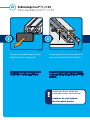
Fig. 6
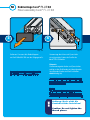
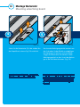
Vormontage Anker gerade
Befestigen Sie die Anker, gerade (Fig. 2, Nr.1) an
den geraden Enden folgender Prole:
• 2 mal an einem Ende des Prols
40x80x1072mm (Fig. 4, Nr.3)
• 2 mal an den Prolen mit Winkel links 23°
40x80x586mm (Fig. 4, Nr.5)
Achtung: Gewindestifte der
Querstücken erst bei der end-
gültigen Montage festziehen!
1
2
3
4
5
2
5
Pre-assembly straight anchor piece
Secure the straight anchor piece (Fig. 2, No. 1) to
the straight ends of the following proles:
• twice at one end of the prole
40x80x1072mm (Fig. 4, No. 3)
• twice on the proles with 23° angle to the left
40x80x586mm (Fig. 4, No. 5)
Caution: Only tighten the
threaded pins of the cross
pieces with the nal assembly.

12
3
6
5
Montage Universalfuß
Assembly of universal foot
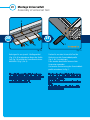
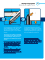
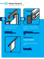
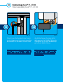
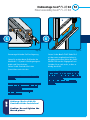
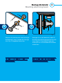
Vormontage Biegeanker
Befestigen Sie die Biegeanker, 23° / -23°
(Fig. 2, Nr.2 / 3) an den schrägen Enden
folgender Prole:
• 2 mal an den Enden der Prole mit Winkel
links 23° / rechts 23° 40x80x1182mm
(Fig. 4, Nr.2)
• 2 mal an den Enden der Prole mit Winkel
links 23° 40x80x586mm (Fig. 4, Nr.5)
Fig. 8
Vormontage der geraden Anker.
Der Abstand zwischen Prol und Ankerkopf
sollte ca. 5mm betragen.
Achten Sie dabei auf die mittige Ausrichtung
der Anker anhand der Markierung.
Pre-assembly of the straight anchors.
The distance between prole and anchor head
should be approx. 5 mm.
Ensure a central alignment of the anchors using
the marking.
Fig. 7
Achtung: Noch nicht die
Gewindestifte festziehen!
Caution: Do not tighten theth-
readed pieces!
6
1
4
Pre-assembly of the bent anchors
Secure the bent anchors, 23° / -23°
(Fig. 2, No. 2 / 3) to the oblique ends
of the following proles:
• 2 x on the end of the proles with angles
left 23° / right 23° 40x80x1182mm
(Fig. 4, No. 2)
• 2 x on the ends of the proles with angles
left 23° 40x80x586mm (Fig. 4, No. 5)

13
1
4
5
66
1 3
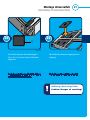
Bringen Sie die Anker mittig in
die Kopfenden der Prolstücke ein.
Die Spitze der Gewindestifte der Querstücken
(Fig. 4, Nr. 6) wird in eine Vertiefung des Ankers
geführt.
Die Querstücken werden seitlich in die Bohrun-
gen der Prolstücke eingebracht.
Fixieren Sie die Anker mit Hilfe der Gewindestifte
der Querstücken.
6
Fig. 9
Montage Universalfuß
Assembly of universal foot
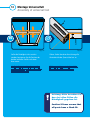
Die Vierkantkopfanker lassen sich in T-förmige
Nuten an den jeweiligen Prolen einbringen.
Für die spätere Montage des mittleren Prols
(Fig. 4, Nr.3) führen Sie vor der Montage der
schrägen Seitenprole (Fig. 4, Nr.2) zwei Anker
mit Vierkantkopf (Fig. 2, Nr.4), an denen Sie die
Blattfedern (Fig. 2, Nr.5) in Einschubrichtung
befestigt haben, in die T-Nuten des Prols
(Fig. 4, Nr.1) ein.
Achten Sie dabei auf die mittige Ausrichtung der
Anker anhand der Markierung.
Fig. 10
7
Achtung: Noch nicht festziehen!
Caution: Do not tighten!
Insert the anchor screws centrally into the head
ends of the prole pieces.
The tips of the threaded pins of the cross pieces
(Fig. 4, No. 6) are guided into an indentation
of the anchor. The cross pieces are introduced
laterally into the drill holes of the prole pieces.
Fix the anchors with the help of the threaded
pins of the cross pieces.
The square-headed anchors can be introduced
in to the T-shaped grooves on the respective
proles.
For the later assembly of the middle prole (Fig.
4, No. 3), prior to assembly of the oblique, side
prole (Fig. 4, No. 2), introduce into the T-slots
of the prole (Fig. 4, No. 1), two square headed
anchor pieces (Fig. 2, No 4), to which you have
attached (in the slide-in direction), the leaf
springs (Fig. 2, No. 5) ,
Pay attention to the central alignment of the
anchor pieces using the marking.

14
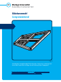
Befestigen Sie die Seitenprole (Fig. 4, Nr.2) am
vorderen Prol (Fig. 4, Nr.1).
Achten Sie dabei auf bündige Ausrichtung.
12
9
Fig. 11
Montage Universalfuß
Assembly of universal foot
Nun die Prole (Fig. 4, Nr.5) in die Seitenprole
(Fig. 4, Nr.2) einschieben.
5
2
8
Fig. 12
Achtung: Noch nicht die
Gewindestücke festziehen!
Bevor der Universalfuß zu-
sammengebaut wird, müs-
sen die Gummiabdeckpro-
le auf die Prole 2 und 3
gesteckt werden (Fig. 1 und
Fig. 24).
Caution: Do not tighten
thethreaded pieces!
Before the universal foot
is assembled, the rubber
protective proles must be
placed on proles 2 and 3
(Fig. 1 and Fig. 24).
Achtung: Nutzen Sie dafür
die selben Nuten wie für die
Vierkantankerschrauben!
Caution: Use the same slots
as for the square headed
screws.
Attach the side proles (Fig. 4, No. 2) to the
front prole (Fig. 4, No. 1).
Take care to achieve a ush alignment.
Now insert the proles (Fig. 4, No. 5) into the
side proles (Fig. 4, No. 2).

15
5
3
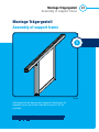
Anschließend wird das mittige Prol
(Fig. 4, Nr.3) montiert.
1
2
5
3
10
Fig. 13
Montage Universalfuß
Assembly of universal foot
Dabei werden die vormontierten Anker der
Prole (Fig. 4, Nr.5) in die Nuten des mittigen
Prols (Fig. 4, Nr.3) eingeschoben.
11
Fig. 14
Subsequently, the middle prole
(Fig. 4, No. 3) is mounted.
At the same time push the pre-assembled
anchors of the proles (Fig. 4, No. 5) into the
grooves of the middle prole (Fig. 4, No. 3).

16
860 mm 860 mm
1
3
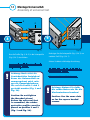
Achten Sie bei der Montage des Prols
(Fig. 4, Nr.3) auf mittige Positionierung.
Nutzen Sie hierzu die Markierung am Prol
(Fig. 4, Nr.1).
13
Fig. 16
Montage Universalfuß
Assembly of universal foot
Verbinden Sie danach das mittige Prol
(Fig. 4, Nr.3) mithilfe der vormontierten
Vierkant-Anker (Fig. 2, Nr.4). Führen Sie vorher
zwei Querstücke seitlich in die Bohrungen des
mittigen Prols ein (Fig. 2, Nr.6).
1
36
12
Fig. 15
4
Take care when tting the prole
(Fig. 4, No. 3) that the position is central. To
this end use the marking on the prole (Fig.
4, No. 1).
After this connect the central prole
(Fig. 4, No. 3) with the help of the previously
assembled square-headed anchor piece (Fig. 2,
No. 4). Guide two crosspieces beforehand la-
terally into the bore holes of the central prole
(Fig. 2, No. 6).

17
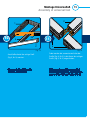
2
4
3
2
540 mm
540 mm
Richten Sie die Prole (Fig. 4, Nr.5) so aus, dass
beide die gleiche Höhe haben.
14
Fig. 17
Montage Universalfuß
Assembly of universal foot
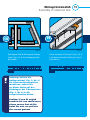
Zur Komplettierung des Aufbaus wird das
Prol mit Langloch (Fig. 4, Nr.4) mit seinen
Nuten über die vormontierten Anker der
Prole (Fig. 4, Nr.2/3) geschoben.
Achten Sie darauf, dass die Langlöcher nach
oben zeigen.
15
Fig. 18
Align the proles (Fig. 4, No. 5) so that both are
at the same height.
To complete the assembly, the prole with
the elongated hole (Fig. 4, No. 4) has its slots
pushed over the previously mounted anchors of
the prole (Fig. 4, No. 2/3).
Take care that the elongated holes face up-
wards.

18
4
2
Ziehen Sie bei korrekter Ausrichtung alle
Gewindestifte der Querstücke fest an.
17
Fig. 20
Montage Universalfuß
Assembly of universal foot
Sollte die Bündigkeit nicht erreicht
werden, korrigieren Sie die Position der
beiden mittleren Prole nach oben
bzw. unten.
16
Fig. 19
Achtung: Bitte beachten Sie
dass bei allen Teilen die
Bündigkeit gegeben ist.
Caution! Please ensure that
all parts have a ush t.
With correct alignment, tighten all the
threaded pins of the crosspieces.
If a ush t is not achieved correct the
position of the two central proles either
upwards or downwards.

19
5
1.
2.
3.
Achtung: Sollten Sie
Auagewinkel (Fig. 3, Nr.6)
für Sonnenschirmgewichte
montieren, achten Sie
an dieser Stelle auf das
Einbringen der T-Nutensteine
(Fig. 3, Nr.5) in die
entsprechenden Nuten.
Caution: If you t angled
brackets for sun shade bases,
please ensure that at this
point the nuts are put into
the correct grooves.
18
Fig. 21
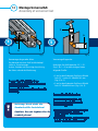
Montage Universalfuß
Assembly of universal foot
Führen Sie jeweils 3 T-Nutsteine (Fig. 3, Nr.5)
in die oberen Nuten der Prole wie in Fig. 22
ersichtlich ein.
19
Fig. 22
Nachfolgend wird die Montage der Auage-
winkel (Fig. 3, Nr.6) für die Gegengewichte
beschrieben.
Introduce in each case 3 T-nuts (Fig. 3, No. 5) in
the upper grooves of the proles as shown in
Fig. 22.
Below is a description of the mounting of the
support brackets (Fig. 3, No. 6) for the counter
weights.

20
1
Drehen Sie nun den Universalfuß auf die
Rückseite, um die Gummiabdeckprole
(Fig. 3, Nr.1) anzubringen.
Dazu werden die offenen Nuten auf der
Unterseite verwendet.
Die korrekte Positionierung der Gummiabdeck-
prole entnehmen Sie Fig. 1.
21
Fig. 24
Befestigen Sie nun jeweils 3 Auagewinkel
(Fig. 3, Nr.6) an den oberen Nuten der Prole
(vgl. Fig. 23) mithilfe der Linsenanschschrau-
ben M8x14 (Fig. 3, Nr.4).
Fig. 23
Montage Universalfuß
Assembly of universal foot
6
5
4
20
Now turn the universal foot onto its reverse
side, in order to put on the rubber protective
proles (Fig. 3, No. 1).
To do this, the open grooves underneath are
used.
See Fig. 1 for the correct positioning of the
rubber cover proles.
Now attach 3 support brackets in each case
(Fig. 3, No. 6) to the top grooves of the proles,
cf Fig. 23 with the help of the button head
screws M8x14 (Fig. 3, No. 4).
Seite laden ...
Seite laden ...
Seite laden ...
Seite laden ...
Seite laden ...
Seite laden ...
Seite laden ...
Seite laden ...
Seite laden ...
Seite laden ...
Seite laden ...
Seite laden ...
Seite laden ...
Seite laden ...
Seite laden ...
Seite laden ...
Seite laden ...
Seite laden ...
Seite laden ...
Seite laden ...
Seite laden ...
Seite laden ...
Seite laden ...
Seite laden ...
Seite laden ...
Seite laden ...
Seite laden ...
Seite laden ...
Seite laden ...
Seite laden ...
Seite laden ...
Seite laden ...
Seite laden ...
Seite laden ...
Seite laden ...
Seite laden ...
Seite laden ...
Seite laden ...
Seite laden ...
Seite laden ...
Seite laden ...
Seite laden ...
Seite laden ...
Seite laden ...
Seite laden ...
Seite laden ...
Seite laden ...
Seite laden ...
Seite laden ...
Seite laden ...
Seite laden ...
Seite laden ...
Seite laden ...
Seite laden ...
Seite laden ...
Seite laden ...
Seite laden ...
Seite laden ...
Seite laden ...
Seite laden ...
Seite laden ...
Seite laden ...
Seite laden ...
Seite laden ...
Seite laden ...
Seite laden ...
Seite laden ...
Seite laden ...
Seite laden ...
Seite laden ...
Seite laden ...
Seite laden ...
Seite laden ...
Seite laden ...
Seite laden ...
Seite laden ...
Seite laden ...
Seite laden ...
Seite laden ...
Seite laden ...
-
 1
1
-
 2
2
-
 3
3
-
 4
4
-
 5
5
-
 6
6
-
 7
7
-
 8
8
-
 9
9
-
 10
10
-
 11
11
-
 12
12
-
 13
13
-
 14
14
-
 15
15
-
 16
16
-
 17
17
-
 18
18
-
 19
19
-
 20
20
-
 21
21
-
 22
22
-
 23
23
-
 24
24
-
 25
25
-
 26
26
-
 27
27
-
 28
28
-
 29
29
-
 30
30
-
 31
31
-
 32
32
-
 33
33
-
 34
34
-
 35
35
-
 36
36
-
 37
37
-
 38
38
-
 39
39
-
 40
40
-
 41
41
-
 42
42
-
 43
43
-
 44
44
-
 45
45
-
 46
46
-
 47
47
-
 48
48
-
 49
49
-
 50
50
-
 51
51
-
 52
52
-
 53
53
-
 54
54
-
 55
55
-
 56
56
-
 57
57
-
 58
58
-
 59
59
-
 60
60
-
 61
61
-
 62
62
-
 63
63
-
 64
64
-
 65
65
-
 66
66
-
 67
67
-
 68
68
-
 69
69
-
 70
70
-
 71
71
-
 72
72
-
 73
73
-
 74
74
-
 75
75
-
 76
76
-
 77
77
-
 78
78
-
 79
79
-
 80
80
-
 81
81
-
 82
82
-
 83
83
-
 84
84
-
 85
85
-
 86
86
-
 87
87
-
 88
88
-
 89
89
-
 90
90
-
 91
91
-
 92
92
-
 93
93
-
 94
94
-
 95
95
-
 96
96
-
 97
97
-
 98
98
-
 99
99
-
 100
100


in anderen Sprachen
- English: twall "Plus" User manual
Sonstige Unterlagen
-
Electrolux EB3SL7KSP Installationsanleitung
-
Electrolux EB3GL3SP Installationsanleitung
-
Electrolux EVYP0946AX Installationsanleitung
-
Trixie 39343 Assembly Instructions
-
Monstertech Collective Mount Benutzerhandbuch
-
AEG 795 Benutzerhandbuch
-
Hilti MSP-Solarpark Bedienungsanleitung
-
Lifetime 60042 Bedienungsanleitung
-
-