
270416 1
SAFE CM
CM Manufactory GmbH
Otto-Hahn-Str. 3
D-72406 Bisingen
Tel. +49-(0)7476-9495-0
Fax. +49-(0)7476-9495-195
www.automation-safety.de
Zielgruppe/
Target audience
Zeichenerklärung/
Explanation of
signs
Einleitung
Diese Bedienungsanleitung soll Sie mit dem
Sicherheitsrelais SAFE CM vertraut
machen.
Die Bedienungsanleitung richtet sich an
folgende Personen:
Qualifizierte Fachkräfte, die
Sicherheitseinrichtungen für Maschinen
und Anlagen planen und entwickeln und
mit den Vorschriften über
Arbeitssicherheit und Unfallverhütung
vertraut sind.
Qualifizierte Fachkräfte, die
Sicherheitseinrichtungen in Maschinen
und Anlagen einbauen und in Betrieb
nehmen.
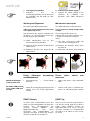
In dieser Bedienungsanleitung werden
einige Symbole verwendet, um wichtige
Informationen hervorzuheben:
Dieses Symbol steht vor Textstellen, die
unbedingt zu beachten sind. Nichtbeachtung
führt zur Verletzung von Personen oder zu
Sachbeschädigung.
Dieses Symbol kennzeichnet Textstellen,
die wichtige Informationen enthalten.
Dieses Zeichen kennzeichnet
auszuführende Tätigkeiten.
Nach diesem Zeichen wird beschrieben, wie
sich der Zustand nach einer ausgeführten
Tätigkeit ändert.
© Copyright Alle Rechte vorbehalten. Änderungen, die dem
technischen Fortschritt dienen, vorbehalten.
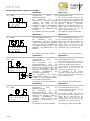
SAFE CM
Original Bedienungsanleitung
Sicherheitsschaltgerät für Sicherheits-
schaltmatten und Sicherheitsleisten
Original operating instructions
Safety controller for mat- and contact
edges
Introduction
This operating instruction should make
you familiar with the safety relay SAFE
CM.
The operating instruction is addressed to
the following persons:
Skilled personnel who plan or
develop safety equipment for
machines and plants and are familiar
with the safety instructions and safety
regulations.
Skilled personnel who build in safety
equipment into machines and plants
and activate them.
The operating instruction contains
several symbols which are used to high-
light important information:
This symbol shows text passages which
should absolutely payed attention too.
Non-observance leads to serious injuries
or damage to property.
This symbol shows passages which
contain important information.
This sign is placed for activities.
This sign shows a description how the
condition has changed after an activity
has been carried out.
© Copyright All rights reserved. Changes, which serve
technical improvements, are reserved.
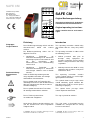
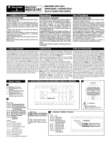
A1 S36
14 24
PWR
CH1
CH2
SAFE CM
A1
14 24 34 42
A2
34 44
S32
S33 S34
S11
S12 S21 S22
S35
S37

270416 2
SAFE CM
Bestimmungsgemäße
Verwendung /
Intended application
Zu Ihrer Sicherheit
For your safety
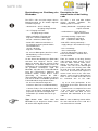
Sicherheitshinweise
Das Sicherheitsschaltgerät SAFE CM ist
bestimmt für den Einsatz in:
Ein- oder zweikanaligen Schaltungs-
technik für Sicherheitsschaltmatten oder
Sicherheitsschaltleisten.
Personen- und Sachschutz sind nicht mehr
gewährleistet, wenn das SAFE CM nicht
entsprechend seiner bestimmungsgemäßen
Verwendung eingesetzt wird.
Beachten Sie unbedingt die folgenden
Punkte:
Das SAFE CM darf nur unter Beachtung
dieser Bedienungsanleitung von
Fachpersonal installiert und in Betrieb
genommen werden, das mit den
geltenden Vorschriften über
Arbeitssicherheit und Unfallverhütung
vertraut ist. Elektrische Arbeiten dürfen
nur von Elektrofachkräften durchgeführt
werden.
Beachten Sie die jeweils gültigen
Vorschriften, insbesondere hinsichtlich
der Schutzmaßnahmen.
Reparaturen, insbesondere das Öffnen
des Gehäuses, dürfen nur vom
Hersteller oder einer von ihm
beauftragten Person vorgenommen
werden. Ansonsten erlischt jegliche
Gewährleistung.
Vermeiden Sie mechanische
Erschütterungen beim Transport oder im
Betrieb; Stöße größer 10g/0,33Hz
können zur Beschädigung des Gerätes
führen.
Montieren Sie das SAFE CM in einem
staub- und feuchtigkeitsgeschützten
Gehäuse (IP54 oder besser); Staub und
Feuchtigkeit können zu
Funktionsstörungen führen.
Sorgen Sie für eine ausreichende
Schutzbeschaltung bei kapazitiven und
induktiven Lasten an den
Ausgangskontakten.
Der Starttaster ist so anzubringen, dass
man beim Start den Gefahrenbereich
einsehen kann
In regelmäßigen Zeitabständen muss
das SAFE CM ausgelöst werden und
auf richtige Funktion geprüft werden
(alle sechs Monate oder im
Wartungszyklus der Anlage).
Safety indications
The safety control device SAFE CM can
be used for:
Single or dual-channel capability for
safety mats or safety contact edges.
Operator and object protection isn’t
guaranteed, if the SAFE CM isn’t be used
by the defined application.
Please pay attention to the following
points:
The SAFE CM may only be build in
and operated by specialized staff,
who are familiar with this instruction
and the current regulations for safety
at work and accident prevention.
Working on electrical equipment is
only allowed for specialized staff.
Pay attention to valid regulations,
particularly in reference to
preventative measures.
Any repairs have to be done by the
manufacturer or a person which is
authorized by the manufacturer. It is
prohibited to open the device or
implement unauthorized changes,
otherwise any warranty expires.
Avoid mechanical vibrations more
than 10g/0,33Hz while transporting
and during operation.
The SAFE CM must be panel
mounted in an enclosure rated at IP
54 or better, otherwise dampness or
dust could lead to function
impairment.
Adequate fuse protection must be
provided on all output contacts with
capacitive and inductive loads.
The start button must installed at a
position from where the dangerous
area could be seen and observed.
The safety controller SAFE CM
should be tested in a defined time
period (every six months or after
each check of the plant).

270416 3
SAFE CM
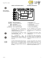
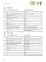
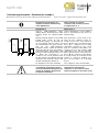
Blockschaltbild
Function diagram
S11, S21
S12, S22
S32, S33
S34
S35
S36, S37
14, 24, 34, 44
Aufbau und Funktionsweise
Sichere Steuerausgänge
Sicherheitseingänge
Verknüpfungskonfiguration
Start-Eingang
Moduswahl (1/2-kanalig)
Sichere Resistorbewertung
Sichere Halbleiterausgänge
Die Start-, Verknüpfungs- und Sicherheits-
eingangskontakte sind entsprechend des
Verwendungszweckes zu verdrahten (s.
„Montage und Inbetriebnahme“).
Für das Betreiben des Gerätes im „UND“
Verknüpfungsmodus muss das Gerät
entsprechend konfiguriert sein.
Die Ausgangskreise und die
Sicherheitsausgänge des Gerätes sind
kurzschlussfest. Sie werden getaktet und
von beiden internen Controllern unabhängig
überwacht.
Im aktiven Zustand leuchten die LEDs CH1,
CH2, an den Ausgängen liegt das positive
Potenzial U
B
an. Im inaktiven Zustand
blinken eventuell, CH1 und/oder CH2 (siehe
Seite 6) - die Ausgänge haben das Potenzial
0V (GND).
Assembly and function
Safety control outputs
Safety inputs
Combination circuit configuration
Start circuit input
Operating mode (1/2-channel)
Safety resistor recognition
Safety semiconductor outputs
The start, combination and safety input
contacts have to be wired according to
the intended purpose (see "Mounting and
start-up").
For the operation of the device in “AND”
combination mode, it must be configured
according to this.
The output circuits and the safety outputs
of the device are short circuit protected.
The output signals are clocked and
independently monitored by both internal
controllers.
In active state of device CH1 and CH2
indicators illuminate. The safety outputs
have the positive potential U
B
. At
inactive state of device CH1 and/or CH2
possibly flash (see page 6) – the safety
outputs have ground potential (0V).
A1 A2
Power
Input circuits
S12 S22 S34 S35 S36
Output
circuits
Combination
circuit
S11 S21 S33
MCU1
<Controller 1>
MCU2
<Controller 2>
Safety output circuits
14
24
34
44
S32S37

270416 4
SAFE CM
Mechanische Montage
Mechanical mounting
Elektrischer Anschluss
Electric connection
Montage und Inbetriebnahme
Für eine sichere Funktion muss das SAFE
CM in ein staub- und feuchtigkeits-
geschütztes Gehäuse (IP54 oder besser)
eingebaut werden.
Montieren Sie das SAFE CM auf eine
Normschiene
Führen Sie die Verdrahtung entsprechend
des Verwendungszweckes durch.
Orientieren Sie sich dabei an den
Anwendungsbeispielen. Generell ist das
SAFE CM nach folgenden Angaben zu
verdrahten:
1. Start- und Rückführungskreis
Automatische Aktivierung ohne
Überwachung des Startkreises: Brücke
zwischen S34 und S11 anschließen.
Überwachter Start: Schließen Sie einen
Starttaster zwischen den Klemmen S34
und S21 an. Dieser Taster darf beim
Einschalten der Versorgungsspannung
nicht betätigt sein.
Überwachen externer Schütze:
Schliessen Sie die Öffnerkontakte der
Schütze in Reihe zu den Klemmen des
gewählten Start-Kreises an.
2. Sicherheitseingange
ACHTUNG: es darf nur eine Applikation
(einkanalig oder zweikanalig) am Gerät
verdrahtet werden. Eine Mischung führt
zum Abschalten des SAFE CM mit
Fehlercodeangabe.
Zweikanalig mit Drahtbruchsicherheit:
Überbrücken Sie die Klemmen S11-S12
und S21-S22 mit den jeweiligen zwei
Signalleitungen der gleichen
Kontaktfläche. Der Widerstand zwischen
zwei Signalleitungen der gleichen
Kontaktfläche soll nicht größer als 20
sein und der Kurzschlusswiderstand
zwischen den beiden Kontaktflächen
nach dem Betreten der Matte oder
Schaltleiste nicht größer als 500 .
Einkanalig mit Drahtbruchsicherheit:
Schließen Sie zwei Leitungen der
diversen Kontaktflächen an die
Klemmen S36 – S37an. Brücken Sie die
anderen zwei Leitungen mit einem
Abschlusswiderstand von 8,2 k ±1%.
3. Verknüpfung konfigurieren
Keine Verknüpfung: Brücken Sie die
Klemmen S32 und S21
UND-Verknüpfung: Klemme S32 bleibt
offen
Mounting and start-up
The SAFE CM must be panel mounted in
an enclosure rated at IP 54 or better,
otherwise dampness or dust could lead
to malfunction.
There is a notch on the rear of the
unit for DIN-Rail attachment.
Carry out the wire appropriate to the
intended purpose according to the
application examples. Generally the
SAFE CM has to be wired regarding the
following specifications:
1. Start and feedback control loop
Automatic activation without
monitoring of reset circuit: bridge S34
and S11.
Start circuit monitoring: connect a
start button between S34 and S21.
The start button must not be closed
when switching on power supply.
Monitor external contactors: connect
the normally closed contacts of the
external contactors in series to the
terminals of current start circuit.
2. Safety input circuits
ATTENTION: Only one application
type (single or dual channel) must be
connected at one time. Otherwise the
SAFE CM will switch off and show
the corresponding error code,
Dual-channel with wire break safety:
Bridge the inputs S11-S12 and S21-
S22 with the both wires of each
contact area. The resistance of both
wires of the same contact area
shouldn’t be higher than 20 and the
short circuit resistance between both
contact areas shouldn’t be higher
than 500 in case of entering the
mat.
Single-channel connection with wire
break safety: connect the (NC)
contact of the periphery module to
S36-S37. Bridge the two responding
wires with an resistor 8k2 ±1%.
3. Setup Combination Mode
No combination: Bridge S32 with S21
AND combination: Terminal S32
remains non connected

270416 5
SAFE CM
Blinkende Anzeigen
Flashing indicators
Die Power LED leuchtet
nicht / Power LED does
not light
4. Versorgung anschließen
Schließen Sie die
Versorgungsspannung an die Klemmen
A1 (+24VDC) und A2 (Gnd) an. LED
PWR leuchtet
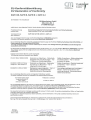
Wartung und Reparatur
Das SAFE CM arbeitet wartungsfrei
Führen Sie einen Klemmenwechsel nicht
unter Spannung durch!
Zum Austausch des Gerätes empfehlen wir
die Kabel 1 zu 1 abzuschrauben und an das
Austauschgerät anzuschrauben.
(1) Kabel abschrauben und an das
Austauschgerät anschrauben.
(2) Nehmen Sie das defekte Gerät von der
Normschiene
(3) Montieren Sie das neue Gerät auf die
Normschiene
Fehler, Störungen, Auswirkung
und Maßnahmen
Zustandsanzeige / Fehler-Tabelle
beachten.
Wenn die Versorgungsspannung korrekt
anliegt, muss das Gerät eingeschickt
werden.
RESET Hinweis
Im Falle einer Fehlermeldung kann das
Gerät aus Sicherheitsgründen nur durch das
Trennen vom Versorgungsnetz neu
gestartet werden (RESET). Eine
Applikationsänderung nach Reset
verursacht eine Fehlermeldung. Es
empfiehlt sich daher in Reihe zum A1-Kreis
einen Reset-Schalter zu installieren.
4. Connecting to power supply
Connect the supply voltage to the
terminals A1 (+24VDC) and
A2.(Gnd). LED PWR illuminates
Maintenance and repair
The SAFE CM works maintenancefree.
Do not execute a clamp change under
voltage!
For exchange of the device, we
commend to screw off the terminals 1 to
1 and to rescrew on the exchange-
device.
(1) You must screw off the cable and
screw on the exchange devise.
(2) Remove the defective device from
the DIN rail
(3) Mount the new device on the DIN rail
Errors, faults, effects and
measures
Look at the failure / status indication
table.
Internal error please send back the
device to CM Manufactory GmbH.
RESET tip
In the case of a error message the device
can only be started again by cut off the
power supply (RESET). Change of
application after reset causes an error
massage. Therefore it is recommended
to install a reset-switch in series to the
A1-circuit.
1
2
3

270416 6
SAFE CM
Beschreibung zur Ermittlung des
Blinkcodes
Die LED`s CH1 und CH2 zeigen diverse
Betriebszustände an. Es werden folgende
Zustände angezeigt:
- dauerhaft ein = alles in Ordnung
Ausgänge freigeschaltet
- aus = Eingang nicht aktiv
Ausgänge abgeschaltet
- blinkt regelmäßig = Eingang aktiv
langsam = wartet auf Startsignal
schnell = wartet auf „UND“-Signal
- beide LED`s blinken wechselweise =
Versorgungsspannung außerhalb des
Toleranzbereiches
schnell = oberhalb
langsam = unterhalb
- bis 12 kurze Blinksignale dann Pause und
Wiederholung = externer Fehler =
siehe Tabelle unten
An der Anzahl der Blinkimpulse (Blinkcode)
zwischen den längeren Pausen, kann
abgelesen werden, welcher externen Fehler
aufgetreten ist. Gezählt werden immer die
Lichtimpulse der Leuchtdioden. Die Summe
der gezählten Lichtimpulse ergibt den
Blinkcode. Mit Hilfe der Fehlercodetabelle
kann die Fehlerursache lokalisiert und
behoben werden. Treten diverse Fehler
gleichzeitig ein, können die LED`s
unterschiedliche Fehler anzeigen. In diesem
Fall müssen beide Leuchtdioden gemäß der
Fehlercodetabelle ausgewertet werden.
- bis 16 kurze Unterbrechungen des
Leuchtens dann Pause und Wiederholung
= interner Fehler = Reset durchführen und
wenn sich der Fehler wiederholt, Gerät zur
Reparatur einschicken mit Angabe der
Fehlercodes (Es werden die Pausen ge
zählt).
Tipp: Blinken beide LED’s, kann der
Blinkcode besser abgelesen werden, wenn
die andere LED abgedeckt wird.
Description for the
determination of the flashing
code
The LED `s CH1 and CH2 indicate
various operating conditions. The
following states are shown
- durably illuminated = everything in order
outputs activated
- not illuminated = inputs deactive
outputs deactivated
- constantly flashing = input active
slow = waiting for start signal
..fast = waitint for “AND” signal
- both LED`s flashing alternately =
supply voltage is out of tolerance range
..fast = overvoltage
slow = undervoltage
- up to 12 short flashing signals then
break and repetition = external error =
see table below
From the number of flashing (flashing
code) between longer tracing, can be
read off, which external errors arose.
Always the light pulses the LED are
counted. The sum of the counted light
pulses results in the flashing code With
the help of the error code table the error
cause can be located and repaired. If
various errors occur at the same time,
different errors may be indicated by the
LEDs. In this case both error codes must
be evaluated due to the table.
- up to 16 short interruptions of the
illumination of the LEDs, then break and
repetition
= internal error = accomplish Reset and
if the error occurs repeatedly, please
send the SAFE CM back to riese
electronic with information of the error
code
Hint: In case of flashing of both LED’s,
the error code will be easier read off, if
one of the LED’s is covered.

270416 7
SAFE CM
Code Tabelle
Code
Fehler und mögliche Ursachen
Behebungsmaßnahmen
1
Verbindung mit Eingang S32, S33 nicht korrekt
Gerät vom Netz trennen, auf Verdrahtungsfehler
prüfen
2
Kurzschluss gegen Masse oder +24V an einem
der Ausgänge oder Überlastung 14, 24, 34, 44
Gerät vom Netz trennen, auf Verdrahtungsfehler
prüfen, ggf. Laststrom prüfen
3
Querschluss oder Fehlfunktion an einem der
Ausgänge 14, 24, 34, 44
Gerät vom Netz trennen, Verdrahtung
4
Querschluss oder Kurzschluss zu VCC an Not-
Halt-Kreisen S11, S12, S21, S22
Gerät vom Netz trennen, auf Verdrahtungsfehler
prüfen
5
Kurzschluss zu GND an Not-Halt-Kreisen S11,
S12, S21, S22
Gerät vom Netz trennen, auf Verdrahtungsfehler
prüfen
6
Unzulässige Applikation oder Verdrahtungsfehler
Gerät vom Netz trennen, auf Verdrahtungsfehler
prüfen
7
Änderung oder falsche Startverdrahtung S11,
S21, S34
Gerät vom Netz trennen, auf Verdrahtungsfehler
prüfen
8
Änderung der Verdrahtung an S35 im laufenden
Betrieb S11, S21, S35
Gerät vom Netz trennen, auf Verdrahtungsfehler
prüfen
9
Versorgungsspannung außerhalb der
Betriebsparameter - Unterspannung
Gerät vom Netz trennen, auf Verdrahtungsfehler
prüfen, Spannungsversorgung prüfen
10
Versorgungsspannung außerhalb der
Betriebsparameter - Überspannung
Gerät vom Netz trennen, auf Verdrahtungsfehler
prüfen, Spannungsversorgung prüfen
12
Mattenfehler oder Abschlusswiderstand an S36,
S37 nicht korrekt
Der Widerstand 8,2k Ω ±1% darf nur bei
einkanaliger Applikation angeschlossen sein. Auf
Verdrahtungsfehler prüfen
Table of codes
Code
Errors and possible causes
Error elimination
1
Combination of inputs S32, S33 incorrect
Switch off the power supply, check the application
for wiring errors
2
Short circuit to GND or +24V or overload of at
least one of the output circuits 14, 24, 34, 44
Switch off the power supply, check current
application for wiring errors or lower load resistance
3
Cross circuit or malfunction of at least one of the
outputs 14, 24, 34, 44
Switch off the power supply, check the application
for wiring errors
4
Short circuit to 24VDC or cross circuit between
S11, S12, S21, S22 emergency stop circuits
Switch off the power supply, check the application
for wiring errors
5
Short circuit between S11, S12, S21, S22
emergency stop circuits GND
Switch off the power supply, check the application
for wiring errors
6
Application incorrect or wiring error
Switch off the power supply, check the application
for wiring errors
7
Wrong wiring at start or changing of wiring while
running at S11, S21, S34
Switch off the power supply, than check application
for wiring errors
8
Changing of wiring of safety circuit S35 while
running
Switch off the power supply, than check application
for wiring errors
9
Supply voltage is out of range - undervoltage
Switch off the power supply, check supply output
values
10
Supply voltage is out of range -overvoltage
Switch off the power supply, check supply output
values
12
Matt failure or Resistor S36 – S37 incorrect
Only 8,2k Ω ±1% is allowed in single channel
applications. Check the application for wiring errors.

270416 8
SAFE CM
Technische Daten / Technical data
Elektrische Daten
Electrical details
Versorgungsspannung
Supply voltage
24V DC
Spannungsbereich
Voltage range
80...125%
Leistungsaufnahme bei 24VDC ohne Last
Power consumption at 24VDC without load
3 W
Stromaufnahme der Eingangskreise (pro
Eingang)
Current consumption of the input circuits
(each input)
I 10mA / 24V DC (typ. 8 mA)
Max. Belastung der Ausgänge S11/S21
Maximum load at output circuits S11/S21
I
MAX
50mA / 24V DC
Stromaufnahme des UND Eingangs (S33)
Current consumption at AND input (S33)
I
MAX
10mA / 24V DC (typ. 8 mA)
Kontaktdaten
Contact details
Sicherheitsausgänge
Safety outputs
4
Schaltvermögen der Sicherheitsausgänge
14, 24, 34, 44, Summenstrom
Switching capacity of safety outputs
14, 24, 34, 44, total current
1,8 A
Anzugsverzögerung
Delay on energisation
Dual-channel 140ms,
Single-channel 360ms
Ansprechzeit (Rückfallverzögerung)
Response time (Delay on deenergisation)
30ms
Einschaltverzögerung nach RESET
Switch-on delay after RESET
Dual-channel 460ms,
Single-channel 680ms
Ausschaltverzögerung UND Kreis
Switch-off delay at AND circuit
30ms
Einschaltverzögerung UND Kreis
Switch-on delay at AND circuit
140ms
Minimale Deaktivierungszeit
Minimum deactivation time
50 ms
Kriech- und Luftstrecken
Verschmutzungsgrad:
Überspannungskategorie:
Creeping and air distance
Pollution grade:
Over voltage category :
EN 50178
2
3
For use in Pollution Degree 2 Environment
Mechanische Daten
Mechanical details
Gehäusematerial
Brennbarkeitsklasse (UL94)
Housing material
Combustibility class (UL94)
Polyamid PA 6.6
V0
Abmessungen (B x H x T)
Dimensions (W x H x D)
22,5 x 100 x 115mm
Gewicht mit Klemmen
Weight with terminals
max. 125g
Lagerung
Storage
In trockenen Räumen / in dry areas
Umgebungsdaten
Environmental details
Umgebungstemperatur
Operating temperature
-25... +55 °C
Maximum surrounding air temperature 55°C
Lagertemperatur
Storage temperature
-25... +75 °C
Luftfeuchte (keine Betauung)
Humidity (no dewing)
<75%
Schutzart Klemmen
Protection type terminals
IP 20
Schutzart Gehäuse
Protection type housing
IP 20
Stoßfestigkeit
Shock resistance
10g, 0,33Hz
Leitungsdaten
Cable cross details
Leiteranschluss (Litze (Cu))
Contactor connection (strand)
0,2 mm
2
-1,5mm²
Use copper wire only. Use 60/75°C Copper
Conductors Only. Min. conductor size AWG22.
Anzugsmoment für Anschlussklemmen
Torque setting for connection terminals
0,5… 0,6 Nm
(Tighten to 1 N.m. Overtorquing may cause
enclosure breakage.)
Max. Leitungslängen (Ein- Ausgangskreis)
Max. contactor length (input / output circuit)
200 m
Empfohlener Leiterquerschnitt (Cu)
Recommended contactor cross section
Use copper wire only!
1,5 mm
2
Typische Kapazität
Typical capacity
150 nF/km
Typischer Widerstand 1,5 mm²
Typical resistance 1,5 mm²
11,7 Ohm/km
Zulassungen
Approvals
Geprüft nach
tested in accordance with
EN ISO 13849-1
Erreichtes Level/Kategorie
achieved level/category
Performance Level e, Kat./Cat. 4
MTTFd [Jahre]
MTTFd [years]
163 “hoch/high”
DC
DC
99% “hoch/high”
CCF
CCF
erfüllt / achieved
Ergänzende Informationen gemäß
Supplementary details according to
EN 61508:2001 (SIL3)
PFH (1/h)
PFH (1/h)
2,87
.
10
-9
PFD (1/h)
PFD (1/h)
2,01
.
10
-6
SFF
SFF
0,9573

270416 9
SAFE CM
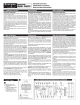
Anwendungsbeispiele / Application examples
Applikation 1
Application 1
A1 +24VDC
A2 0VDC
S34
S35
S22
S12S11
S21
S32
S33
S36 S37
2-kanalige Anwendung mit
automatischem Start und
Drahtbruchsicherheit.
Die Schaltmatte muss die
Eingangskreise (S11/S12, S21/S22)
schließen. Die Brücke S34-S11
konfiguriert das Gerät für den
automatischen Start. Die Aktivierung der
Ausgänge erfolgt, bei getrennten
Kontaktflächen der Schaltmatte (nicht
betreten).
Dual channel application with auto-start
and broken wire check.
The safety mat switch must close the
input circuits (S11/S12, S21/S22), and
the S11-S34 has to be brigded for auto-
start configuration. The bridge between
S21-S32 activates stand-alone
application (no AND connection). The
outputs will be activated when the
contact areas of the mat are not
connected (mat not entered)
bis Kategorie 4; SIL3; PLe erreichbar
up to category 4; SIL3; PLe reachable
Applikation 2
Application 2
A1 +24VDC
A2 0VDC
S35
S34
S22
S12S11
S21
S32
S33
S36 S37
2-kanalige Anwendung mit überwachtem
Start und Drahtbruchsicherheit.
Die Schaltmatte muss die
Eingangskreise (S11/S12, S21/S22)
schließen. Die Aktivierung der Ausgänge
erfolgt, bei getrennten Kontaktflächen
der Schaltmatte (nicht betreten), nach
Betätigung und Wiederloslassen der
Starttaste.
Dual-channel application with monitoring
of reset circuit and broken wire check.
The safety mat switch must close the
input circuits (S11/S12, S21/S22. The
outputs will be activated when the
contact areas of the mat are not
connected (mat not entered) and the
start button is pressed and released.
bis Kategorie 4; SIL3; PLe erreichbar
up to category 4; SIL3; PLe reachable
Applikation 3
Applikation 3
A1 +24VDC
A2 0VDC
S33
S36
S37
14 34
K1
K2
A2
K1
K2
S34
S22S12
S11
S21
S32
8k2
K1
K2
S35
1-kanalige Anwendung mit
automatischem Start und
Drahtbruchsicherheit.
Die Schaltmatte mit dem
Abschlusswiderstand muss den
Eingangskreis (S36/S37) schließen. Die
Brücke S34-S11 konfiguriert das Gerät
für den automatischen Start. Die
Aktivierung der Ausgänge erfolgt, bei
getrennten Kontaktflächen der
Schaltmatte (nicht betreten).
Zur Überwachung der externen
Schützkontakte werden die Öffner-
Kontakte der zwangsgeführten Schütze
in den Startkreis eingebunden.
Single-channel application with auto
start and broken wire check.
The mat with final resistance must be
connected to S36 and S37. Auto start is
activated by bridge between S34-S11.
The outputs will be activated when the
contact areas of the mat are not
connected (mat not entered)
For monitoring of the external
conductors, the NC contacts of the force
guided contactors must be attached in
series to the start circuit
bis Kategorie 4; SIL3; PLe erreichbar
up to category 4; SIL3; PLe reachable
Applikation 4
Applikation 4
A1 +24VDC
A2 0VDC
S35
S33
S36
S37
S22
S12
S21
S32
8k2
S34
S11
1-kanalige Anwendung mit
überwachtem Start und
Drahtbruchsicherheit.
Die Schaltmatte mit dem
Abschlusswiderstand muss den
Eingangskreis (S36/S37) schließen. Die
Aktivierung der Ausgänge erfolgt, bei
getrennten Kontaktflächen der
Schaltmatte (nicht betreten), nach
Betätigung und Wiederloslassen der
Starttaste.
1-channel application with monitoring of
reset circuit and broken wire check.
The mat with final resistance must be
connected to S36 and S37.
The safety mat switch must close the
input circuits (S11/S12, S21/S22. The
outputs will be activated when the
contact areas of the mat are not
connected (mat not entered) and the
start button is pressed and released.
bis Kategorie 4; SIL3; PLe erreichbar
up to category 4; SIL3; PLe reachable

270416 10
SAFE CM
Verknüpfungssbeispiele / Combination examples
Bitte Beachten Sie auch Punkt 3 auf Seite 4 Montage und Inbetriebnahme: Please notice item 3 on Page 4: Mounting and start-up
Beispiel für den Anschluss von
Schützen und deren Überwachung
siehe Applikation 3
Wiring example for external
contactors and monitoring of them,
see application no. 3
Applikation 5
Application 5
S32
S33
24
S11
K1
K2
K3
K4
14
A
B
24
14
safety
input
safety
input
Logische UND-Verknüpfung zweier
SAFE-C-Geräte, hierbei können A und B
beliebige Geräte der SAFE-C-Familie
sein.
Wird der Not-Halt-Schalters von Gerät A
betätigt fallen K1/K2 ab. Da die
Sicherheitsausgänge von Gerät A jetzt
ein 0V-Potenzial anliegen haben und
das Gerät B durch die offene Klemme
S32 für eine UND-Verknüpfung
konfiguriert wurde, werden die Schütze
K3/K4 über den Anschluss S33 (logische
UND-Verknüpfung) abgeschaltet. Wird
hingegen nur die Schutztür geöffnet, die
an Gerät B angeschlossen ist,
schalteten auch nur die Schütze K3/K4
ab. Die Schütze K1/K2 bleiben weiterhin
angezogen. Das Gerät A schaltet somit
alle ihm nachfolgenden Geräte ab.
Logical AND linkage of two SAFE-C-
devices. A and B may be any devices of
SAFE C family.
After opening the e-stop circuits of the
device A, the contactors K1/K2 de-
energise. Because the safety outputs of
device A have now a 0V-pontial and the
device B is configured for the AND-
combination (through the open circuit
S32), the contactors K3/K4 will be de-
energised over the S33 terminal (AND
combination) too. If only the safety gate
will be opened which is connected to the
device B, the contactors K3/K4 will be
de-energised only. The contactors K1/K2
remains in energised condition. The
device A de-energises all it following
devices.
bis Kategorie 4; SIL3; PLe erreichbar
up to category 4; SIL3; PLe reachable
Bei Verwendung von mehreren
untereinander verknüpften Geräten
mit unterschiedlichen Kategorien gilt
jeweils die niedrigste Kategorie für
die gesamte Schaltung.
When using several among themselves
linked devices with different
categories, in each case the lowest
safety level applies to the entire circuit.

-
 1
1
-
 2
2
-
 3
3
-
 4
4
-
 5
5
-
 6
6
-
 7
7
-
 8
8
-
 9
9
-
 10
10
-
 11
11


CM riese Safe CM Original Operating Instructions
- Typ
- Original Operating Instructions
- Dieses Handbuch eignet sich auch für
in anderen Sprachen
- English: CM riese Safe CM
Verwandte Artikel
Andere Dokumente
-
SICK UE48-3OS Bedienungsanleitung
-
-
 Allen-Bradley MINOTAUR MSR144RTP Benutzerhandbuch
-
-
 Allen-Bradley Guardmaster MINOTAUR MSR121RT Installationsanleitung
-
-
Fracarro SIG7282 Bedienungsanleitung
-
EDWARDS INT-22.5R1-24 Installationsanleitung
-
-

